2000 MITSUBISHI MONTERO relay
[x] Cancel search: relayPage 522 of 1839

DIESEL FUEL <4M4> -Troubleshooting13C-31
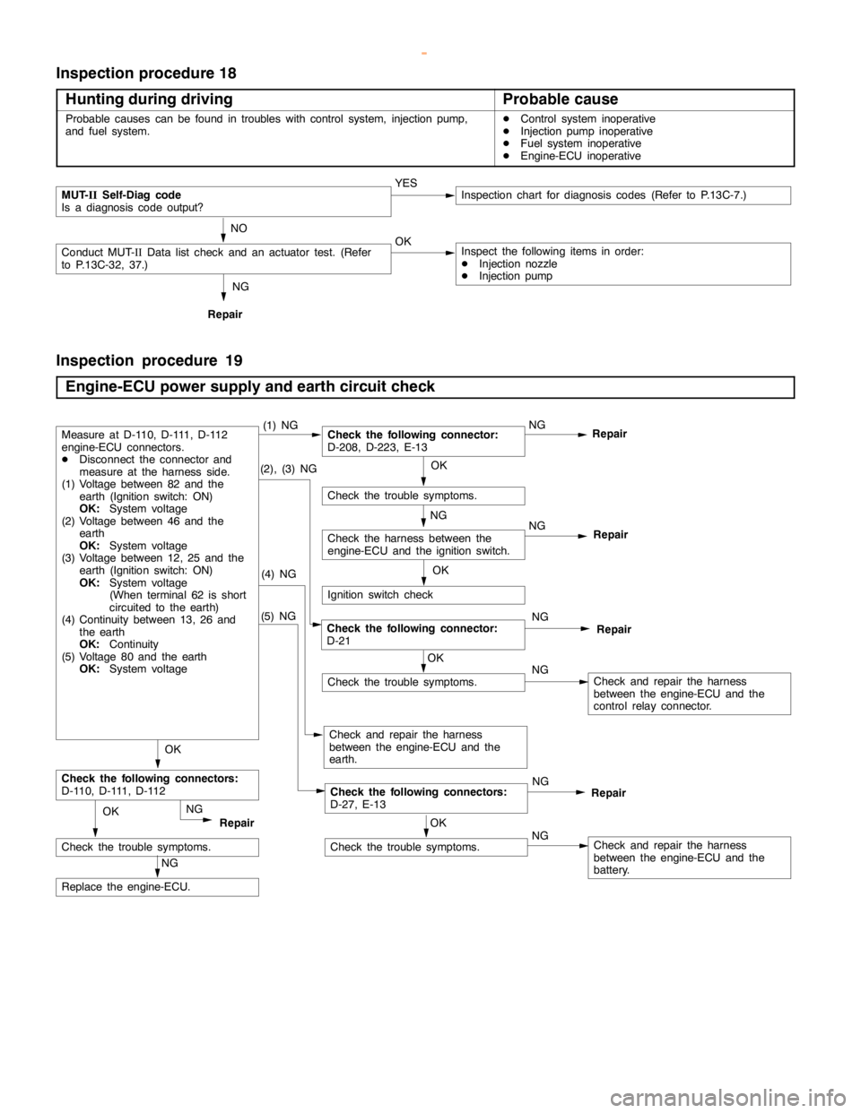
Inspection procedure 18
Hunting during driving
Probable cause
Probable causes can be found in troubles with control system, injectionpump,
and fuel system.DControl system inoperative
DInjection pump inoperative
DFuel system inoperative
DEngine-ECU inoperative
NG
Repair
MUT-
IISelf-Diag code
Is a diagnosis code output?YESInspection chart for diagnosis codes (Refer to P.13C-7.)
NO
Conduct MUT-IIData list check and an actuator test. (Refer
to P.13C-32, 37.)OKInspect the following items in order:
DInjection nozzle
DInjection pump
Inspection procedure 19
Engine-ECU power supply and earth circuit check
(5) NG
Check the trouble symptoms.
NG
Repair
(2), (3) NGOK
Check the trouble symptoms.
OK
NG
Check the harness between the
engine-ECU and the ignition switch.
Ignition switch check
(4) NG
Check and repair the harness
between the engine-ECU and the
earth.
OK
Check the following connectors:
D-110, D-111, D-112
NG
Replace the engine-ECU.
OK
Check the trouble symptoms.
Check the following connectors:
D-27, E-13Repair NG
NG
RepairCheck the following connector:
D-21
NG
Check and repair the harness
between the engine-ECU and the
control relay connector.
NG
Repair
OK
Check the trouble symptoms.NGCheck and repair the harness
between the engine-ECU and the
battery.
Check the following connector:
D-208, D-223, E-13NG
RepairMeasure at D-110, D-111, D-112
engine-ECU connectors.
DDisconnect the connector and
measure at the harness side.
(1) Voltage between 82 and the
earth (Ignition switch: ON)
OK:
System voltage
(2) Voltage between 46 and the
earth
OK:
System voltage
(3) Voltage between 12, 25 and the
earth (Ignition switch: ON)
OK:
System voltage
(When terminal 62 is short
circuited to theearth)
(4) Continuity between 13, 26 and
the earth
OK
:Continuity
(5) Voltage 80 and the earth
OK:
System voltage(1) NG
OK
www.WorkshopManuals.co.uk
Purchased from www.WorkshopManuals.co.uk
Page 525 of 1839

DIESEL FUEL <4M4> -Troubleshooting13C-34
Item
No.Reference
page Code No.
or inspec-
tion proce-
dure No. Value to be
determined
as normal Inspection conditions Check item
21GE actuatorEngine: After warmingIdling20 - 30%Code No.13C-17
up the engine2,500 r/min20 - 30%26 or No.13C-21
High idling20 - 29%48
22EGR dutyEngine: Idling0 - 100%*2––
valueEngine: After warming up the engine
23Control
sleeve posi-Engine: After warming
up the engineIdling1.535 -
1.735 VCode No.
2613C-17
tion (actual
value)2, 500 r/minSlightly de-
creased.
High idling1.884 -
2.084 V
24Accelerator
pedal posi-Ignition switch: ONAccelerator pedal:
Idling position0.9 - 1.1 VCode No.
2713C-18
tion sensor
(sub)Accelerator pedal:
Fully opened position4.1V or
higher
25Accelerator
pedal posi-Ignition switch: ONAccelerator pedal:
Idling position0%Code No.
2713C-18
tion sensor
(sub)Accelerator pedal:
Fully opened position99 - 100%
NOTE
*1: The opening degree of the timing control valve is converted into percentage. (0%: timer non-advanced angle,
100%: timer maximum advanced angle)
*
2: The opening degree of the EGR solenoid valve is converted into percentage.
Item
No.
Check itemInspection conditionsValue to be
determined
as normalCode No.
or inspec-
tion proce-
dure No.Reference
page
41Idle switchIgnition switch: ON
(check by repeatedRelease the foot from
the accelerator pedal.ON––
accelerator operation)Step on the accelerator
pedal slightly.OFF
43A/C switchEngine: Idling (The
A/C compressorA/C switch: ONON––
should be in operation
when the A/C switch is
“ON”)A/C switch: OFFOFF
44IgnitionIgnition switch: ONEngine: StopOFF––
switch-STEngine: CrankingON
45Ignition
switch-IGIgnition switch: ONON––
46Control
relayIgnition switch: ONON––
47A/C relayEngine: Idling after
warming up the engineA/C switch: OFFOFF (A/C
compressor
clutch not in
operation)––
A/C switch: ONON (A/C
compressor
clutch in op-
eration)
www.WorkshopManuals.co.uk
Purchased from www.WorkshopManuals.co.uk
Page 526 of 1839

DIESEL FUEL <4M4> -Troubleshooting13C-35
Item
No.Check itemInspection conditionsValue to be
determined
as normalCode No.
or inspec-
tion proce-
dure No.Reference
page
50Condenser
fan relayIgnition switch: ONA/C switch: OFF
(engine coolant tem-
perature at 109_Cor
higher)
A/C switch: ON
(engine coolant tem-
perature at 109_Cor
higher or no higher
than 109_C and the
vehicle speed at 60
km/h or slower)ON––
A/C switch: OFF
(engine coolant tem-
perature at 109_Cor
lower)
A/C switch: ON
(engine coolant tem-
perature at 109_Cor
lower or no higher than
109_C and the vehicle
speed at 60 km/h or
faster)OFF
52Glow plug
relayIgnition switch:
OFF®ONEngine coolant tem-
perature at 60_Cor
lowerON––
Engine coolant tem-OFF
perature at 60_Cor
higher
53Main throttleIgnition switch: ON (Engine stops)OFF––
solenoid
valveEngine: Idling after warming up the engineON
54Sub throttleEngine: Idling after warming up the engineOFF––
solenoid
valveEngine: Idling®Stop (within 3 seconds)ON
55EngineIgnition switch: OFF®ONON (For 5Procedure13C-25
warning
lampseconds)No. 3
56Glow lampIgnition switch:
OFF®ONThe engine coolant
temperature at 60_C
or lowerON––
The engine coolant
temperature at 60_C
or higherOFF
www.WorkshopManuals.co.uk
Purchased from www.WorkshopManuals.co.uk
Page 527 of 1839

DIESEL FUEL <4M4> -Troubleshooting13C-36
Item
No.Reference
page Code No.
or inspec-
tion proce-
dure No. Value to be
determined
as normal Inspection conditions Check item
58NeutralIgnition switch: ONN, P rangeN, P––
switchNone of the aboveD, R
60Fuel cut
relayIgnition switch: ON®OFF afterwards for a
certain period of timeON––
None of the aboveOFF
61EGR controlTurning off EGR quicklyON––
solenoid
valve No. 2None of the aboveOFF
62AT/MTIgnition switch: ONVehicles with A/TA/T––
switchVehicles with M/TM/T
68A/C switch 2A/C: Under high load or low loadON––
A/C: OFF or under medium loadOFF
69Warm up
switchDWarm up switch: ON
DHeater temperature setting: Maximum
DEngine coolant temperature: 90_C or lower
DBlower fan: ONON––
None of the aboveOFF
70PTC heaterDWarm up switch: ON
DHeater temperature setting: Maximum
DEngine coolant temperature: 65_Cto75_C
or lower
DBlower fan: ONON––
None of the aboveOFF
71PowerPower steering switch: ONON––
steering
switchPower steering switch: OFFOFF
www.WorkshopManuals.co.uk
Purchased from www.WorkshopManuals.co.uk
Page 528 of 1839

DIESEL FUEL <4M4> -Troubleshooting13C-37
ACTUATOR TEST TABLE
Item
No.Check itemDrive Con-
tentsInspection
conditionsValue to be determined
as normalCode No.
or inspec-
tion proce-
dure No.Reference
page
02Glow plug relayTurning theIgnition switch:Battery charge is––
relay from
OFF to ON orONenergized to the glow
plug when the glow
from ON to
OFFplug relay is ON.
03A/C compressorTurning theIgnition switch:The A/C compressor––
relayrelay from
OFF to ON orONclutch makes an
audible sound.
from ON to
OFF
11Timing control
valveTurn the
timing control
valve to ONDIgnition
switch: ON
DEngine:
IdlingMakes an audible
soundCode
No.4313C-20
12Turn the
timing control
valve to OFF
Idling
DTimer piston
position
sensor:
Normal
15Glow lampTurn the glow
lamp on or offIgnition switch:
ONThe glow lamp turns
on––
16Warning lampTurn the
warning lamp
on or offIgnition switch:
ONThe warning lamp
turns onProcedure
No.3, 413C-25
22Condenser fan
relayTurning the
relay from
OFF to ON or
from ON to
OFFIgnition switch:
ONThe condenser fan
rotates.––
23Main throttle
solenoid valveTurn the
solenoid
valve from
OFF to ON or
from ON to
OFFDIgnition
switch: ON
DVehicle
speed:
0 km/h
DEngine
speed:
1,000 r/min
or lowerMakes an audible
soundCode
No.4113C-19
24Sub throttle
solenoid valveTurn the
solenoid
valve from
OFF to ON or
from ON to
OFFDIgnition
switch: ON
DVehicle
speed:
0 km/h
DEngine
speed:
1,000 r/min
or lowerMakes an audible
sound––
www.WorkshopManuals.co.uk
Purchased from www.WorkshopManuals.co.uk
Page 529 of 1839

DIESEL FUEL <4M4> -Troubleshooting13C-38
Item
No.Reference
page Code No.
or inspec-
tion proce-
dure No. Value to be determined
as normal Inspection
conditions Drive Con-
tents Check item
25GE actuatorTurn the GE
actuator to
ONDIgnition
switch: ON
DEngine
speed:
0 r/min orMakes an audible
soundCode
No.4813C-21
26Turn the GE
actuator to
OFF
0 r/min or
lower
DControl
sleeve posi-
tion sensor:
Normal
27Fuel cut solenoid
valveTurn the
solenoid
valve to ONDIgnition
switch: ON
DVehicle
speed:
0 km/hMakes an audible
sound––
28EGR solenoid
valve No.1Turn the
solenoid
valve to ONDIgnition
switch: ON
DVehicleMakes an audible
sound––
29Turn the
solenoid
valve to ONspeed:
0 km/h
30EGR solenoid
valve No.2Turn the
solenoid
valve from
OFF to ON or
from ON to
OFFDIgnition
switch: ON
DVehicle
speed:
0 km/hMakes an audible
sound––
33PTC heaterSwitch the
PTC heater
relay ON/
OFF.DIgnition
switch: ONVoltage on the ECU
terminal No.9: 0 - 1V––
34Middle position
of GE actuatorHold the
injection
governor in
its middle
position.DIgnition
switch: ONWhen the crankshaft
is turned clockwise
during the adjustment
of the injection timing,
the injection pipes
spray out fuel.Code
No.4813C-21
www.WorkshopManuals.co.uk
Purchased from www.WorkshopManuals.co.uk
Page 531 of 1839

DIESEL FUEL <4M4> -Troubleshooting13C-40
Terminal
No.Normal condition: Inspection conditions (engine status) Check item
36Selector switch be-
tween A/T and M/TIgnition switch: ON0-1V
37Inhibitor switchIgnition switch: ON
(Engine stops)Set the selector lever to P
or N0-1V
Set the selector lever to D,
2, L, or RSystem voltage
39Stop lamp switchDepress the brake pedalSystem voltage
40Brake switchDepress the brake pedal0-1V
46Control relayIgnition switch: ON0-1V
Ignition switch: ON®OFF (in about 8 seconds)System voltage
51Engine speed sensor
(backup)Engine: Idling1.5 - 2.5 V
55Accelerator pedal posi-
tion sensor (sub)Ignition switch: ONAccelerator pedal: Idling
position0.9 - 1.1 V
Accelerator pedal: Fully
opened position4.1 V or higher
71Ignition switch-STEngine: Cranking8 V or higher
74Control sleeve positionIgnition switch: ON (Engine stops)2.2 - 2.7 V
73sensor2.0 - 4.0 V
752.0 - 4.0 V
76Timer piston positionIgnition switch: ON (Engine stops)2.2 - 2.7 V
77sensor2.0 - 4.0 V
782.0 - 4.0 V
80Back-up power supplyIgnition switch: OFFSystem voltage
82Ignition switch-IGIgnition switch: ONSystem voltage
83Engine coolant tem-
perature sensorIgnition switch: ONEngine coolant tempera-
ture: 0_C3.4 - 4.5 V
Engine coolant tempera-
ture: 20_C2.6 - 3.6 V
Engine coolant tempera-
ture: 40_C1.8 - 2.5 V
Engine coolant tempera-
ture: 80_C0.7 - 1.1 V
84Accelerator pedal posi-
tion sensor (main)Ignition switch: ONAccelerator pedal: Idling
position0.9 - 1.1 V
Accelerator pedal: Fully
opened position4.1 V or higher
85Boost pressure sensorIgnition switch: ON (760 mmHg)1.2 - 1.6 V
86Vehicle speed sensorDIgnition switch: ON
DMove the vehicle forward slowly0V«5 V (repeat the
change)
www.WorkshopManuals.co.uk
Purchased from www.WorkshopManuals.co.uk
Page 561 of 1839

DIESEL FUEL <4M4> -Troubleshooting13C-6
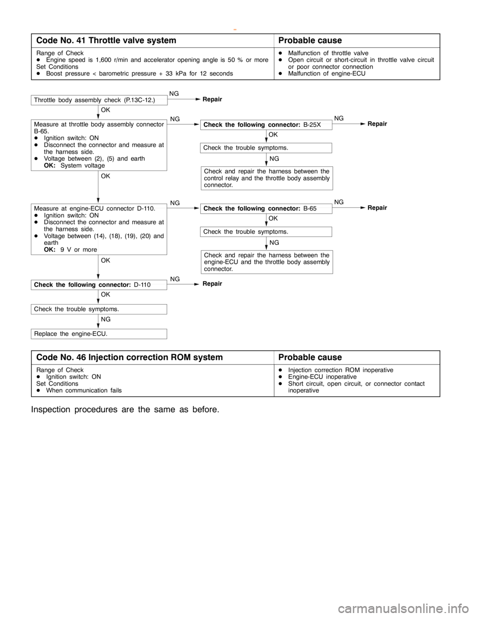
Code No. 41 Throttle valve systemProbable cause
Range of Check
DEngine speed is 1,600 r/min and accelerator opening angle is 50 % or more
Set Conditions
DBoost pressure < barometric pressure + 33 kPa for 12 secondsDMalfunction of throttle valve
DOpen circuit or short-circuit in throttle valve circuit
or poor connector connection
DMalfunction of engine-ECU
NG
Replace the engine-ECU.
OK
Check the trouble symptoms.
OK
NG
Check the following connector:D-110
OK
Check the trouble symptoms.
NG
Check and repair the harness between the
engine-ECU and the throttle body assembly
connector.
Repair NG
OK
Check the following connector:B-65 NG
OK
Check the trouble symptoms.
NG
Check and repair the harness between the
control relay and the throttle body assembly
connector.
Repair NG
OK
Check the following connector:B-25X NGMeasure at throttle body assembly connector
B-65.
DIgnition switch: ON
DDisconnect the connector and measure at
the harness side.
DVoltage between (2), (5) and earth
OK:System voltage
RepairThrottle body assembly check (P.13C-12.)NG
Measure at engine-ECU connector D-110.
DIgnition switch: ON
DDisconnect the connector and measure at
the harness side.
DVoltage between (14), (18), (19), (20) and
earth
OK:9 V or more
Repair
Code No. 46 Injection correction ROM systemProbable cause
Range of Check
DIgnition switch: ON
Set Conditions
DWhen communication failsDInjection correction ROM inoperative
DEngine-ECU inoperative
DShort circuit, open circuit, or connector contact
inoperative
Inspection procedures are the same as before.
www.WorkshopManuals.co.uk
Purchased from www.WorkshopManuals.co.uk