2000 MITSUBISHI MONTERO relay
[x] Cancel search: relayPage 504 of 1839
DIESEL FUEL <4M4> -Troubleshooting13C-13
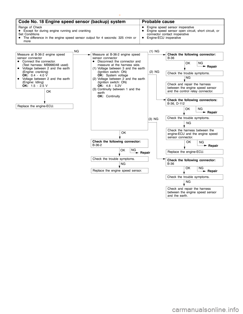
Code No. 18 Engine speed sensor (backup) systemProbable cause
Range of Check
DExcept for duringengine running andcranking
Set Conditions
DThe difference in the enginespeed sensor output for 4 seconds: 325 r/min or
moreDEngine speed sensor inoperative
DEngine speed sensoropencircuit, short circuit, or
connector contact inoperative
DEngine-ECU inoperative
Check the trouble symptoms.
OK
Check and repair the harness
between the enginespeed sensor
and the control relay connector.OK
OK
NG
Repair
(1) NGMeasure at B-36-2 enginespeed
sensor connector
DConnect the connector.
(Test harness: MB998348 used)
DVoltage between 2 and the earth
(Engine: cranking)
OK:
0.4 - 4.0 V
DVoltage between 2 and the earth
(Engine: Idling)
OK:
1.5 - 2.5 V
NG
Replace the enginespeed sensor.
Replace the engine-ECU.
Check the following connector:
B-36
NG
NG
Check the trouble symptoms.
OK
Repair NG
OK
Repair NG NG
OKRepair NG
NG
OKRepair NG
Check the following connector:
B-36-2
Check the trouble symptoms.
Measure at B-36-2 enginespeed
sensor connector
DDisconnect the connector and
measure at the harness side.
(1) Voltage between 3 and the earth
(Ignition switch: ON)
OK:
System voltage
(2) Voltage between 2 and the earth
(Ignition switch: ON)
OK:
4.8 - 5.2V
(3) Continuity between 1 and the
earth
OK:
Continuity(2) NG
(3) NG
Check the harness between the
engine-ECU and the enginespeed
sensor connector.
Replace the engine-ECU.
Check and repair the harness
between the enginespeed sensor
and the earth.
Check the following connector:
B-36
Check the trouble symptoms.
Check the following connectors:
B-36, D-112
www.WorkshopManuals.co.uk
Purchased from www.WorkshopManuals.co.uk
Page 505 of 1839
DIESEL FUEL <4M4> -Troubleshooting13C-14
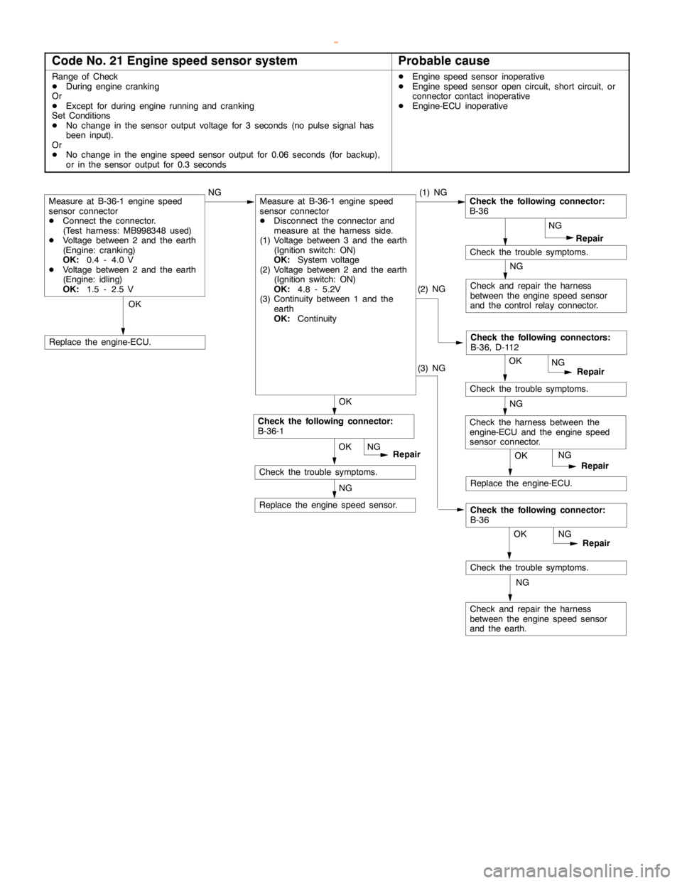
Code No. 21 Engine speed sensor systemProbable cause
Range of Check
DDuring enginecranking
Or
DExcept for duringengine running andcranking
Set Conditions
DNo change in the sensor output voltage for 3 seconds (no pulse signal has
been input).
Or
DNo change in the enginespeed sensor output for 0.06 seconds (for backup),
or in the sensor output for 0.3 secondsDEngine speed sensor inoperative
DEngine speed sensoropencircuit, short circuit, or
connector contact inoperative
DEngine-ECU inoperative
OK
Check and repair the harness
between the enginespeed sensor
and the control relay connector.OK
OK
NG
Repair
(1) NGMeasure at B-36-1 enginespeed
sensor connector
DConnect the connector.
(Test harness: MB998348 used)
DVoltage between 2 and the earth
(Engine: cranking)
OK:
0.4 - 4.0 V
DVoltage between 2 and the earth
(Engine: idling)
OK:
1.5 - 2.5 V
NG
Replace the enginespeed sensor.
Replace the engine-ECU.
Check the following connector:
B-36
NG
NG
Check the trouble symptoms.
OK
Repair
Check the following connectors:
B-36, D-112
NG
OK
Repair NG
Check the harness between the
engine-ECU and the enginespeed
sensor connector.NG
Check the trouble symptoms.
Replace the engine-ECU.
Check and repair the harness
between the enginespeed sensor
and the earth.OK
Repair
Check the following connector:
B-36
NG
NG
Check the trouble symptoms. OK
Repair NG
Check the following connector:
B-36-1
Check the trouble symptoms.
Measure at B-36-1 enginespeed
sensor connector
DDisconnect the connector and
measure at the harness side.
(1) Voltage between 3 and the earth
(Ignition switch: ON)
OK:
System voltage
(2) Voltage between 2 and the earth
(Ignition switch: ON)
OK:
4.8 - 5.2V
(3) Continuity between 1 and the
earth
OK:
Continuity(2) NG
(3) NG
www.WorkshopManuals.co.uk
Purchased from www.WorkshopManuals.co.uk
Page 510 of 1839
DIESEL FUEL <4M4> -Troubleshooting13C-19
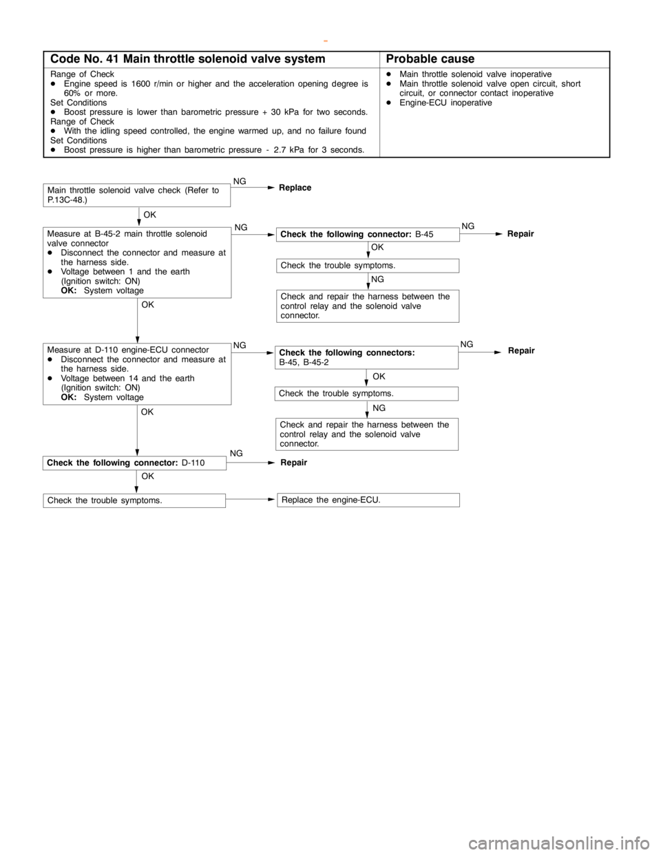
Code No. 41 Main throttle solenoid valve systemProbable cause
Range of Check
DEngine speed is 1600 r/min or higher and the accelerationopening degree is
60% or more.
Set Conditions
DBoost pressure is lower than barometric pressure + 30 kPa for two seconds.
Range of Check
DWith the idlingspeed controlled, theengine warmed up, and no failure found
Set Conditions
DBoost pressure is higher than barometric pressure - 2.7 kPa for 3 seconds.DMain throttle solenoidvalve inoperative
DMain throttle solenoidvalveopencircuit, short
circuit, or connector contact inoperative
DEngine-ECU inoperative
OK
Check the following connector:
B-45NG
Repair
OK
OK
Check and repair the harness between the
control relay and the solenoid valve
connector.
Main throttle solenoidvalve check (Refer to
P.13C-48.)
Check the trouble symptoms.
Replace the engine-ECU.
NG
OK
RepairCheck the following connector:
D-110
Check the trouble symptoms.NGReplace
NG NG
Check the following connectors:
B-45, B-45-2NG
Repair
OK
Check and repair the harness between the
control relay and the solenoid valve
connector.
Check the trouble symptoms.
NG
NGMeasure at D-110 engine-ECU connector
DDisconnect the connector and measure at
the harness side.
DVoltage between 14 and the earth
(Ignition switch: ON)
OK:
System voltageOK
Measure at B-45-2 main throttle solenoid
valve connector
DDisconnect the connector and measure at
the harness side.
DVoltage between 1 and the earth
(Ignition switch: ON)
OK:
System voltage
www.WorkshopManuals.co.uk
Purchased from www.WorkshopManuals.co.uk
Page 511 of 1839
DIESEL FUEL <4M4> -Troubleshooting13C-20
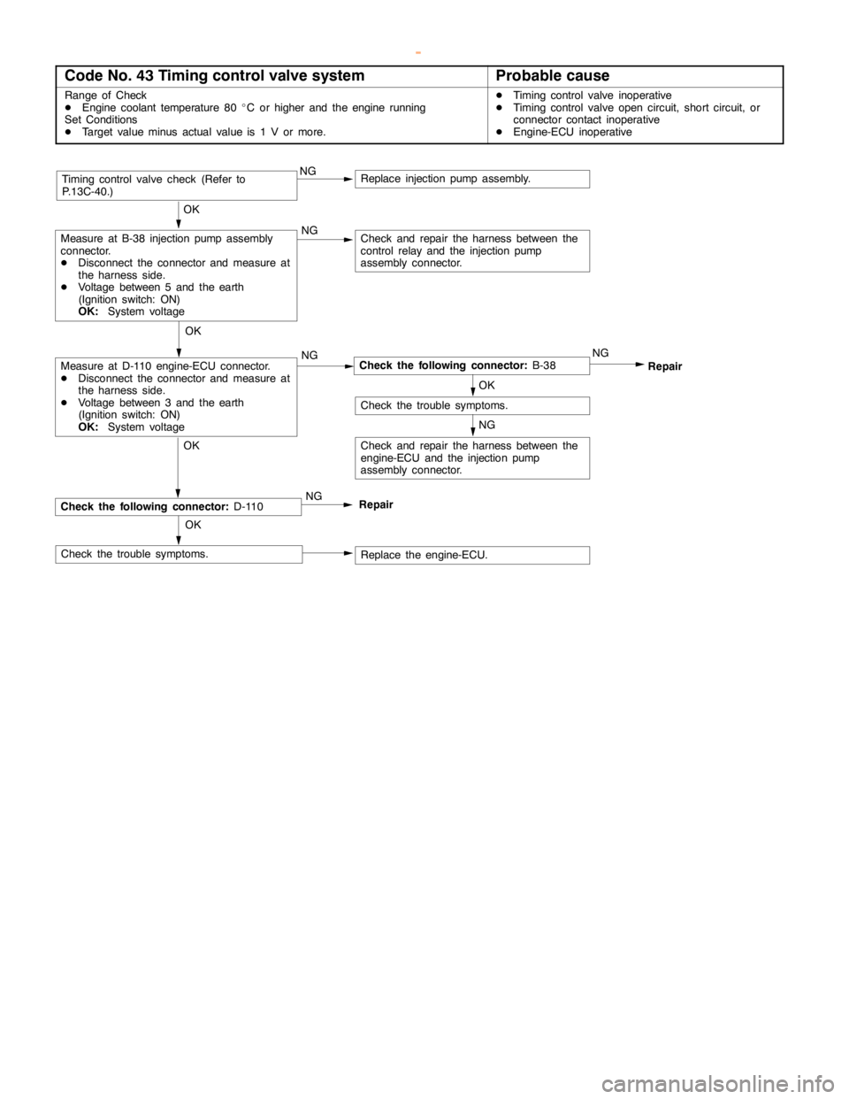
Code No. 43 Timing control valve systemProbable cause
Range of Check
DEngine coolant temperature 80_C or higher and the engine running
Set Conditions
DTarget value minus actual value is 1 V or more.DTiming controlvalve inoperative
DTiming controlvalveopencircuit, short circuit, or
connector contact inoperative
DEngine-ECU inoperative
OK
OK
Check and repair the harness between the
control relay and the injectionpump
assembly connector.
Timing controlvalve check (Refer to
P.13C-40.)
Replace the engine-ECU. OK
RepairCheck the following connector:
D-110
Check the trouble symptoms.NG NG NG
Check the following connector:
B-38NG
Repair
OK
Check the trouble symptoms.
NG
NGMeasure at D-110 engine-ECU connector.
DDisconnect the connector and measure at
the harness side.
DVoltage between 3 and the earth
(Ignition switch: ON)
OK:
System voltageOK
Measure at B-38 injectionpumpassembly
connector.
DDisconnect the connector and measure at
the harness side.
DVoltage between 5 and the earth
(Ignition switch: ON)
OK:
System voltage
Replace injection pumpassembly.
Check and repair the harness between the
engine-ECU and the injection pump
assembly connector.
www.WorkshopManuals.co.uk
Purchased from www.WorkshopManuals.co.uk
Page 512 of 1839
DIESEL FUEL <4M4> -Troubleshooting13C-21
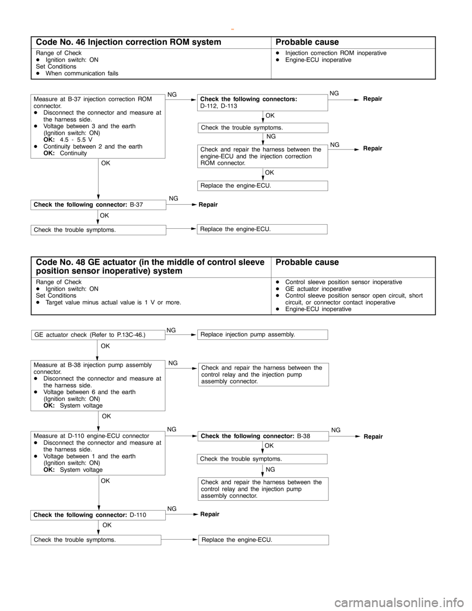
Code No. 46 Injection correction ROM systemProbable cause
Range of Check
DIgnition switch: ON
Set Conditions
DWhen communication failsDInjection correction ROM inoperative
DEngine-ECU inoperative
Repair
OK
Replace the engine-ECU. OK
RepairCheck the following connector:
B-37
Check the trouble symptoms.NG NG
Check the following connectors:
D-112, D-113
NG
Repair
OK
Check the trouble symptoms.
NG
Measure at B-37 injection correction ROM
connector.
DDisconnect the connector and measure at
the harness side.
DVoltage between 3 and the earth
(Ignition switch: ON)
OK:
4.5 - 5.5 V
DContinuity between 2 and the earth
OK:
Continuity
Check and repair the harness between the
engine-ECU and the injection correction
ROM connector.
OK
Replace the engine-ECU.NG
Code No. 48 GE actuator (in the middle of control sleeve
position sensor inoperative) systemProbable cause
Range of Check
DIgnition switch: ON
Set Conditions
DTarget value minus actual value is 1 V or more.DControl sleeve position sensor inoperative
DGE actuator inoperative
DControl sleeve position sensoropencircuit, short
circuit, or connector contact inoperative
DEngine-ECU inoperative
OK
OK
Check and repair the harness between the
control relay and the injectionpump
assembly connector.
GE actuator check (Refer to P.13C-46.)
Replace the engine-ECU. OK
RepairCheck the following connector:
D-110
Check the trouble symptoms.NGNG NG
Check the following connector:
B-38NG
Repair
OK
Check the trouble symptoms.
NG
NGMeasure at D-110 engine-ECU connector
DDisconnect the connector and measure at
the harness side.
DVoltage between 1 and the earth
(Ignition switch: ON)
OK:
System voltageOK
Measure at B-38 injectionpumpassembly
connector.
DDisconnect the connector and measure at
the harness side.
DVoltage between 6 and the earth
(Ignition switch: ON)
OK:
System voltage
Replace injection pumpassembly.
Check and repair the harness between the
control relay and the injectionpump
assembly connector.
www.WorkshopManuals.co.uk
Purchased from www.WorkshopManuals.co.uk
Page 517 of 1839
DIESEL FUEL <4M4> -Troubleshooting13C-26
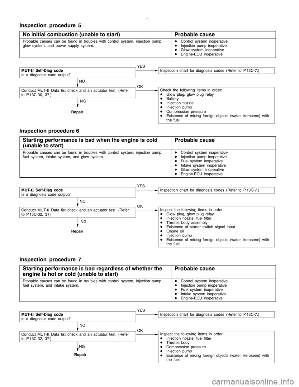
Inspection procedure 5
No initial combustion (unable to start)
Probable cause
Probable causes can be found in troubles with control system, injectionpump,
glow system, and power supply system.DControl system inoperative
DInjection pump inoperative
DGlow system inoperative
DEngine-ECU inoperative
NG
Repair
MUT-
IISelf-Diag code
Is a diagnosis code output?YESInspection chart for diagnosis codes (Refer to P.13C-7.)
NO
Conduct MUT-IIData list check and an actuator test. (Refer
to P.13C-30, 37.)OKCheck the following items in order:
DGlow plug, glowplugrelay
DBattery
DInjection nozzle
DInjection pump
DCompression pressure
DExistence of mixing foreign objects (water, kerosene) with
the fuel
Inspection procedure 6
Starting performance is bad when the engine is cold
(unable to start)
Probable cause
Probable causes can be found in troubles with control system, injectionpump,
fuel system, intake system, and glow system.DControl system inoperative
DInjection pump inoperative
DFuel system inoperative
DIntake system inoperative
DGlow system inoperative
DEngine-ECU inoperative
NG
Repair
MUT-
IISelf-Diag code
Is a diagnosis code output?YESInspection chart for diagnosis codes (Refer to P.13C-7.)
NO
Conduct MUT-IIData list check and an actuator test. (Refer
to P.13C-32, 37)OKInspect the following items in order:
DGlow plug, glowplugrelay
DInjection nozzle, fuel filter
DThrottle body assembly
DExistence of starter switch signal input
DEngine oil
DInjection pump
DExistence of mixing foreign objects (water, kerosene) with
the fuel
Inspection procedure 7
Starting performance is bad regardless of whether the
engine is hot or cold (unable to start)
Probable cause
Probable causes can be found in troubles with control system, injectionpump,
fuel system, and intake system.DControl system inoperative
DInjection pump inoperative
DFuel system inoperative
DIntake system inoperative
DEngine-ECU inoperative
NG
Repair
MUT-
IISelf-Diag code
Is a diagnosis code output?YESInspection chart for diagnosis codes (Refer to P.13C-7.)
NO
Conduct MUT-IIData list check and an actuator test. (Refer
to P.13C-32, 37.)OKInspect the following items in order:
DInjection nozzle, fuel filter
DThrottle body
DCompression pressure
DInjection pump
DExistence of mixing foreign objects (water, kerosene) with
the fuel
www.WorkshopManuals.co.uk
Purchased from www.WorkshopManuals.co.uk
Page 519 of 1839
DIESEL FUEL <4M4> -Troubleshooting13C-28
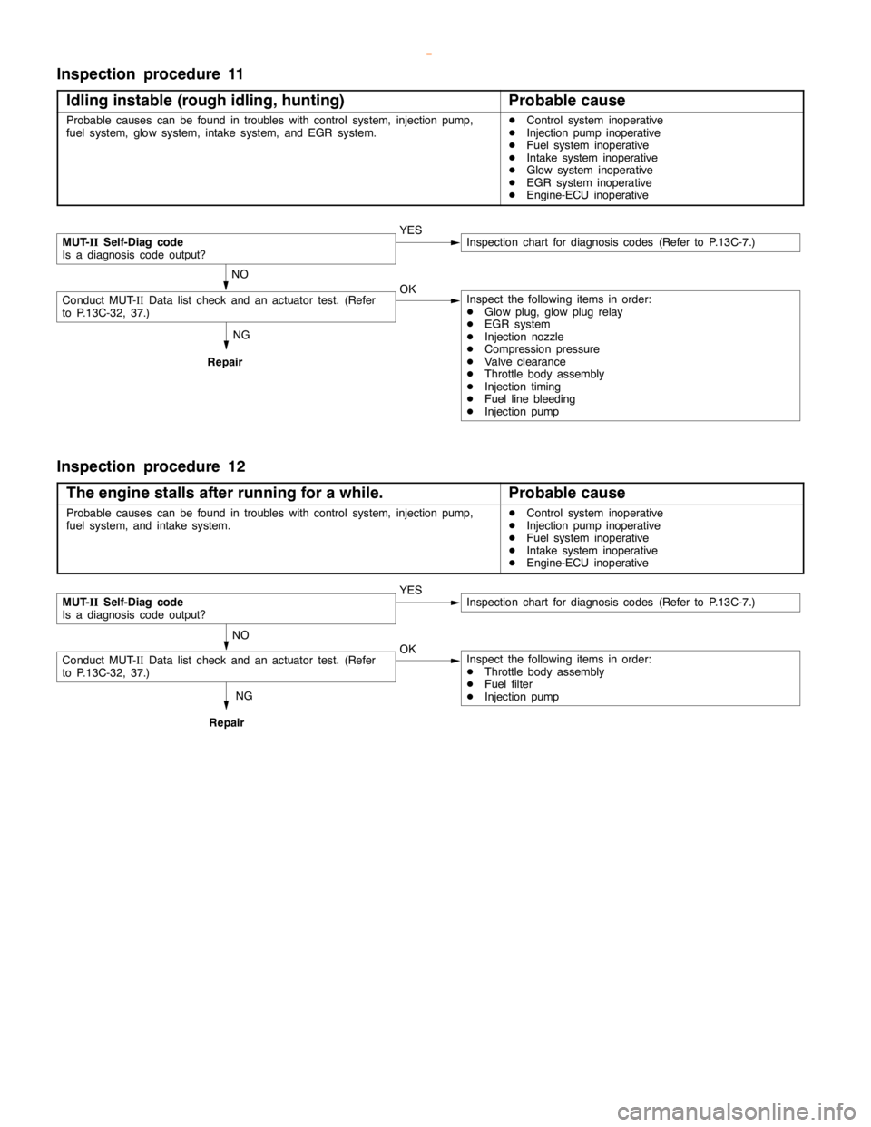
Inspection procedure 11
Idling instable (rough idling, hunting)
Probable cause
Probable causes can be found in troubles with control system, injectionpump,
fuel system, glow system, intake system, and EGR system.DControl system inoperative
DInjection pump inoperative
DFuel system inoperative
DIntake system inoperative
DGlow system inoperative
DEGR system inoperative
DEngine-ECU inoperative
NG
Repair
MUT-
IISelf-Diag code
Is a diagnosis code output?YESInspection chart for diagnosis codes (Refer to P.13C-7.)
NO
Conduct MUT-IIData list check and an actuator test. (Refer
to P.13C-32, 37.)OKInspect the following items in order:
DGlow plug, glowplugrelay
DEGR system
DInjection nozzle
DCompression pressure
DValve clearance
DThrottle body assembly
DInjection timing
DFuel line bleeding
DInjection pump
Inspection procedure 12
The engine stalls after running for a while.
Probable cause
Probable causes can be found in troubles with control system, injectionpump,
fuel system, and intake system.DControl system inoperative
DInjection pump inoperative
DFuel system inoperative
DIntake system inoperative
DEngine-ECU inoperative
NG
Repair
MUT-
IISelf-Diag code
Is a diagnosis code output?YESInspection chart for diagnosis codes (Refer to P.13C-7.)
NO
Conduct MUT-IIData list check and an actuator test. (Refer
to P.13C-32, 37.)OKInspect the following items in order:
DThrottle body assembly
DFuel filter
DInjection pump
www.WorkshopManuals.co.uk
Purchased from www.WorkshopManuals.co.uk
Page 521 of 1839
DIESEL FUEL <4M4> -Troubleshooting13C-30
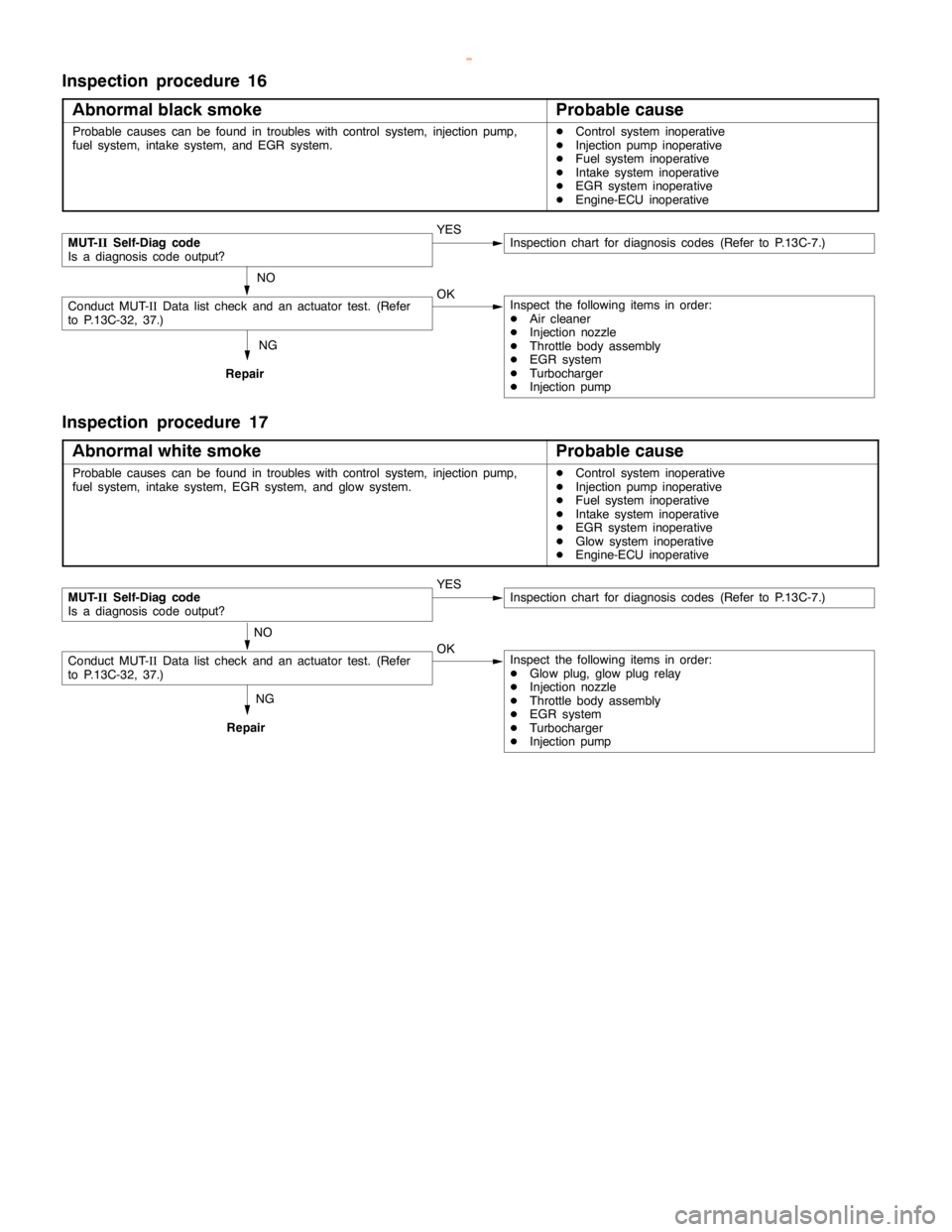
Inspection procedure 16
Abnormal black smoke
Probable cause
Probable causes can be found in troubles with control system, injectionpump,
fuel system, intake system, and EGR system.DControl system inoperative
DInjection pump inoperative
DFuel system inoperative
DIntake system inoperative
DEGR system inoperative
DEngine-ECU inoperative
NG
Repair
MUT-
IISelf-Diag code
Is a diagnosis code output?YESInspection chart for diagnosis codes (Refer to P.13C-7.)
NO
Conduct MUT-IIData list check and an actuator test. (Refer
to P.13C-32, 37.)OKInspect the following items in order:
DAir cleaner
DInjection nozzle
DThrottle body assembly
DEGR system
DTurbocharger
DInjection pump
Inspection procedure 17
Abnormal white smoke
Probable cause
Probable causes can be found in troubles with control system, injectionpump,
fuel system, intake system, EGR system, and glow system.DControl system inoperative
DInjection pump inoperative
DFuel system inoperative
DIntake system inoperative
DEGR system inoperative
DGlow system inoperative
DEngine-ECU inoperative
NG
Repair
MUT-
IISelf-Diag code
Is a diagnosis code output?YESInspection chart for diagnosis codes (Refer to P.13C-7.)
NO
Conduct MUT-IIData list check and an actuator test. (Refer
to P.13C-32, 37.)OKInspect the following items in order:
DGlow plug, glowplugrelay
DInjection nozzle
DThrottle body assembly
DEGR system
DTurbocharger
DInjection pump
www.WorkshopManuals.co.uk
Purchased from www.WorkshopManuals.co.uk