2000 MITSUBISHI MONTERO engine oil
[x] Cancel search: engine oilPage 721 of 1839

INTAKE AND EXHAUST -Turbocharger and Exhaust
Manifold <4M4>15-15
INSTALLATION SERVICE POINT
"
AA
TURBOCHARGER ASSEMBLY INSTALLATION
1. Check the internal surface, the eye bolt and the
mating surface of the oil pipe and water pipe for
clogging, and clean if necessary.
2. If deposits of carbon are accumulated on the
turbocharger oil passage, remove them and clean
using the compressed air.
Caution
Be careful not to allow foreign material to enter the
turbocharger.
3. Add clean engine oil through the oil feed pipe port
on the turbocharger.
INSPECTION
Check the following points; replace the part if a problem is
found.
EXHAUST MANIFOLD CHECK
1. Check for damage or cracking of any part.
2. Using a straight edge and a thickness gauge, check for
distortion of the cylinder head installation surface.
Standard value: 0.15 mm or less
Limit: 0.20 mm
TURBOCHARGER ASSEMBLY CHECK
DVisually check the turbine wheel and the compressor
wheel for cracking or other damage.
DCheck whether the turbine wheel and the compressor
wheel can be easily turned by hand.
DCheck for oil leakage from the turbocharger assembly.
DCheck whether or not the waste gate valve remains open.
If any problem is found, replace the part after disassembly.
OIL PIPE AND OIL RETURN PIPE CHECK
Check the oil pipe and oil return pipe for clogging, bending,
or other damage. If there is clogging, clean it.
EXHAUST MANIFOLD CHECK
Damage or cracking of any part.
www.WorkshopManuals.co.uk
Purchased from www.WorkshopManuals.co.uk
Page 735 of 1839

INTAKE AND EXHAUST -General Information/Service Specifications/Sealant15-3
At starting and driving at low speed, the duty control
value of the variable geometry solenoid valve is
increased to apply the vacuum pressure of the
vacuum pump to the variable geometry actuator.
Applying the vacuum pressure to the variable
geometry actuator pulls the actuator rod so that
it can move towards the direction of closing the
variable nozzle of the variable geometry
turbocharger. As closing the nozzle reduces the
exhaust gas mass, the speed of exhaust gas flow
will be increased and efficiency will be improved.
Since the characteristic of boost pressure becomes
a low speed type, boost pressure will suddenly
rise from low speed.
At driving at high speed, the duty control value
of the variable geometry solenoid valve is
decreased to reduce the vacuum pressure from
the vacuum pump so that the actuator rod can
return to the deactivated status and move towards
the direction of opening the nozzle of the variable
geometry turbocharger.Opening the nozzle allows the characteristic of
boost pressure to become a high speed type so
that the appropriate boost pressure can be
maintained.
Therefore, boost pressure can be controlled by
appropriate duty control of the variable geometry
solenoid valve. The engine-ECU calculates the
correct boost pressure based on the engine speed
and fuel injection amount. Furthermore, the duty
control of the variable geometry solenoid valve is
given feedback of the signals from the variable
geometry control pressure sensor and the boost
pressure sensor so that the variable nozzle opening
angle of the variable geometry turbocharger can
be quickly adjusted to obtain the desired boost
pressure.
SERVICE SPECIFICATIONS
ItemsStandard value
Variable geometry actuator activation vacuum
(Approximately 1 mm stroke) kPaApproximately 10.5 - 12.5
Variable geometry solenoid valve coil resistance
(at 20°C)Ω29 - 35
SEALANT
ItemSpecified sealantRemarks
Thread of the intake manifold mounting
bolts3M Stud Locking No.4170 or equivalentAnaerobic sealant
www.WorkshopManuals.co.uk
Purchased from www.WorkshopManuals.co.uk
Page 745 of 1839

INTAKE AND EXHAUST -Turbocharger and Exhaust
Manifold <4M4>15-13
INSTALLATION SERVICE POINT
"AATURBOCHARGER ASSEMBLY INSTALLATION
1. Check the internal surface, the eye bolt and the
mating surface of the oil pipe and water pipe for
clogging, and clean if necessary.
2. If deposits of carbon are accumulated on the
turbocharger oil passage, remove them and clean
using the compressed air.
Caution
Be careful not to allow foreign material to enter the
turbocharger.
3. Add clean engine oil through the oil feed pipe port
on the turbocharger.
www.WorkshopManuals.co.uk
Purchased from www.WorkshopManuals.co.uk
Page 749 of 1839

16-1
ENGINE
ELECTRICAL
CONTENTS
CHARGING SYSTEM 2................
GENERAL INFORMATION 2................
SERVICE SPECIFICATIONS 3..............
SPECIAL TOOL 4.........................
ON-VEHICLE SERVICE 5..................
Alternator Output Line Voltage Drop Test 5....
Output Current Test 6.......................
Regulated Voltage Test 8....................
Waveform Check Using An Analyzer 11.......
ALTERNATOR 13.........................
STARTING SYSTEM 23................
GENERAL INFORMATION 23..............
SERVICE SPECIFICATIONS 24............
STARTER MOTOR 24.....................
IGNITION SYSTEM 37.................
GENERAL INFORMATION 37..............
SERVICE SPECIFICATIONS 38............
SPECIAL TOOL 38.......................
ON-VEHICLE SERVICE 38................
Ignition Coil (With Built-in Power Transistor)
Check 38...................................
Spark Plug Check and Cleaning 39...........
Ignition Failure Sensor Check 40.............
Camshaft Position Sensor Check, Crank angle
Sensor Check, Detonation Sensor Check 40...
IGNITION COIL <6G7> 41.................
CRANKSHAFT ANGLE SENSOR
<6G7> 42................................
CAMSHAFT POSITION SENSOR
<6G7> 42................................
DETONATION SENSOR <6G7> 43.........
GLOW SYSTEM 44....................
GENERAL INFORMATION 44..............
SERVICE SPECIFICATIONS 45............
ON-VEHICLE SERVICE 45................
Self-regulating Glow System Check 45........
Glow & EGR Control Unit Check 48..........
Engine ECU Check 49.......................
Glow Plug Relay Check 50..................
Glow Plug Check 51........................
Engine Coolant Temperature Sensor
Check 51...................................
GLOW PLUG 52..........................
www.WorkshopManuals.co.uk
Purchased from www.WorkshopManuals.co.uk
Page 787 of 1839

ENGINE ELECTRICAL -Ignition System16-39
Voltage: 1.5VTerminal No.
123
When current is
flowing
When current is
not flowing
SECONDARY COIL CHECK
NOTE
It is impossible to check the secondary coil through the
continuity check as a diode is integrated in the secondary
coil circuit of this ignition coil. So, check the secondary coil
in the following procedure.
1. Disconnect the ignition coil connector.
2. Remove the ignition coil and install a new spark plug
to the ignition coil.
3. Connect the ignition coil connector.
4. Earth the side electrode of the spark plug and crank
the engine.
5. Check that spark is produced between the electrodes of
the spark plug.
6. If no spark is produced, replace the ignition coil with a
new one and recheck.
7. If spark is produced with the new ignition coil, replace
the old one as it is faulty. If no spark is produced again,
the ignition circuit is suspected as faulty. Check the ignition
circuit.
SPARK PLUG CHECK AND CLEANING
Caution
1. The spark plug gap for iridium plugs should not be
adjusted.
2. Cleaning iridium plugs may result in damage to the
iridium tip. Therefore, if cleaning is necessary
because the plug is sooty, use a plug cleaner, and
do not clean the plug for more than 20 seconds in
order to preserve the electrodes. A wire brush should
never be used.
3. The spark plugs in GDI engines are special iridium
plugs in which the electrodes can become black even
when the plugs are working normally. Carbon which
may become deposited on these plugs burns off more
readily than with conventional plugs, and so should
not cause any problems with spark plug performance.
Judgement of whether a spark plug is operating
normally or not should be made by checking the
insulation resistance.
www.WorkshopManuals.co.uk
Purchased from www.WorkshopManuals.co.uk
Page 950 of 1839

Page 951 of 1839

Page 952 of 1839

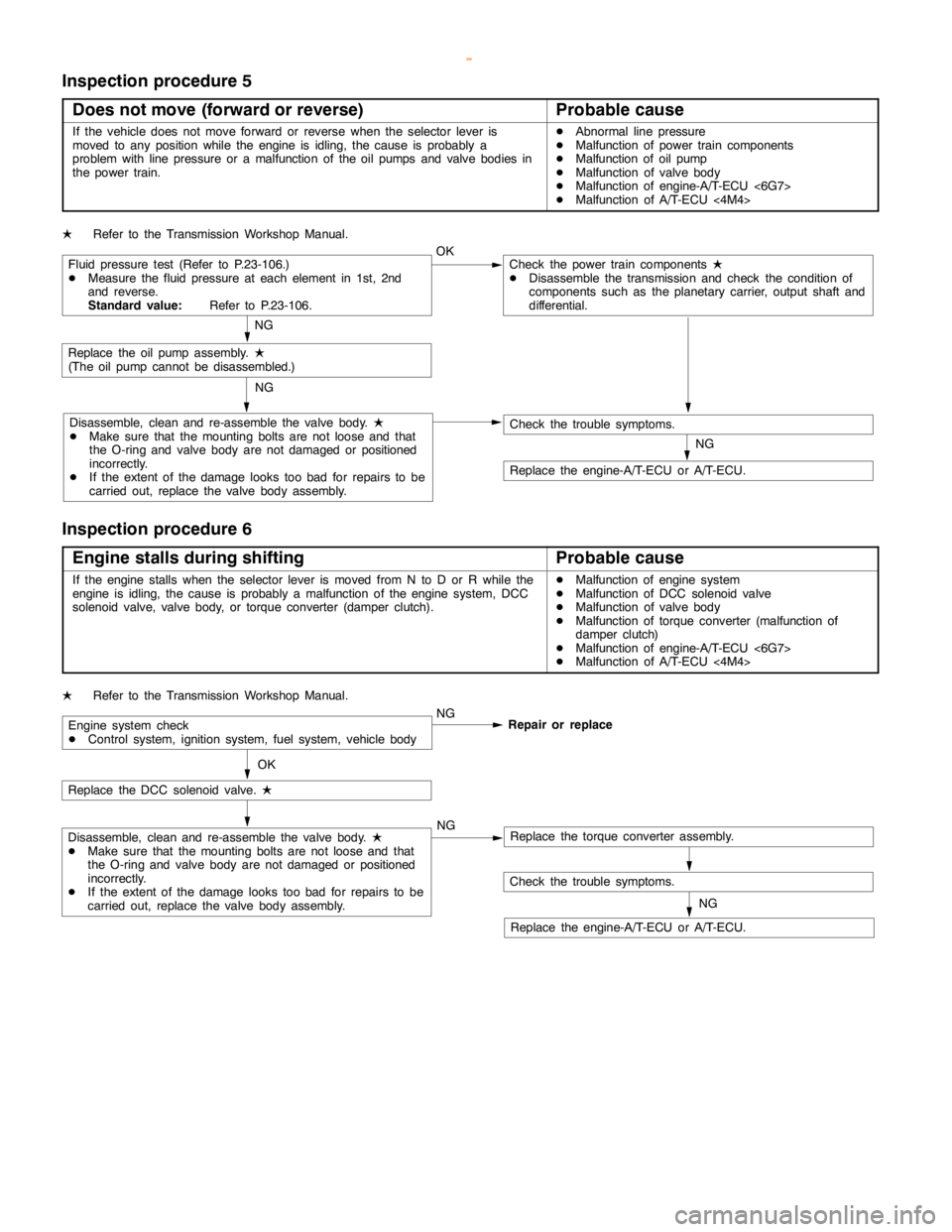
AUTOMATIC TRANSMISSION -Troubleshooting AUTOMATIC TRANSMISSION -Troubleshooting 23-51
Inspection procedure 5
Does not move (forward or reverse)
Probable cause
If the vehicle does not move forward or reverse when the selector lever is
moved to any position while the engine is idling, thecause is probably a
problem with line pressure or a malfunction of the oil pumps and valve bodies in
the power train.DAbnormal line pressure
DMalfunction of power train components
DMalfunction of oil pump
DMalfunction of valve body
DMalfunction of engine-A/T-ECU <6G7>
DMalfunction of A/T-ECU<4M4>
LRefer to the Transmission Workshop Manual.
Fluid pressure test (Refer to P.23-106.)
DMeasure the fluid pressure at each element in 1st, 2nd
and reverse.
Standard value:Refer to P.23-106.OKCheck the power train components
L
DDisassemble the transmission and check the condition of
components such as the planetary carrier, output shaft and
differential.
NG
Replace the oil pumpassembly.
L
(The oilpump cannot be disassembled.)
Disassemble, clean and re-assemble the valve body.
L
DMake sure that the mounting bolts are not loose and that
the O-ring and valve body are notdamaged or positioned
incorrectly.
DIf the extent of thedamagelooks too bad for repairs to be
carried out, replace the valve body assembly.NG
NG
Check the trouble symptoms.
Replace the engine-A/T-ECU or A/T-ECU.
Inspection procedure 6
Engine stalls during shifting
Probable cause
If the enginestalls when the selector lever is moved from N to D or R while the
engine is idling, thecause is probably a malfunction of theenginesystem, DCC
solenoid valve, valve body, or torque converter (damper clutch).DMalfunction of enginesystem
DMalfunction of DCC solenoid valve
DMalfunction of valve body
DMalfunction of torque converter (malfunction of
damper clutch)
DMalfunction of engine-A/T-ECU <6G7>
DMalfunction of A/T-ECU<4M4>
LRefer to the Transmission Workshop Manual.
Engine system check
DControl system, ignition system, fuel system, vehicle bodyNG
Repair or replace
OK
Replace the DCC solenoid valve.
L
Disassemble, clean and re-assemble the valve body.
L
DMake sure that the mounting bolts are not loose and that
the O-ring and valve body are notdamaged or positioned
incorrectly.
DIf the extent of thedamagelooks too bad for repairs to be
carried out, replace the valve body assembly.NGReplace the torque converter assembly.
Check the trouble symptoms.
Replace the engine-A/T-ECU or A/T-ECU.NG
www.WorkshopManuals.co.uk
Purchased from www.WorkshopManuals.co.uk