2000 MITSUBISHI MONTERO engine oil
[x] Cancel search: engine oilPage 267 of 1839
GDI -Troubleshooting
OK
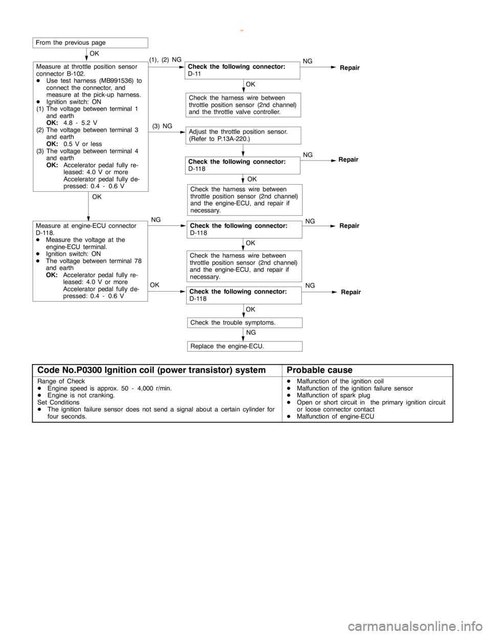
Measure at throttle position sensor
connector B-102.
DUse test harness (MB991536) to
connect the connector, and
measure at the pick-up harness.
DIgnition switch: ON
(1) The voltage between terminal 1
and earth
OK:
4.8 - 5.2 V
(2) The voltage between terminal 3
and earth
OK:
0.5 V or less
(3) The voltage between terminal 4
and earth
OK:
Acceleratorpedalfully re-
leased: 4.0 V or more
Acceleratorpedalfully de-
pressed: 0.4 - 0.6 V(1), (2) NG
NGRepair
Check the following connector:
D-118NG
Repair
OK
Check the harness wire between
throttle position sensor (2nd channel)
and the throttle valve controller.
From the previouspage
(3) NG
Adjust the throttle position sensor.
(Refer to P.13A-220.)
OK
Check the harness wire between
throttle position sensor (2nd channel)
and the engine-ECU, and repair if
necessary.OK
Measure at engine-ECU connector
D-118.
DMeasure the voltage at the
engine-ECU terminal.
DIgnition switch: ON
DThe voltage between terminal 78
and earth
OK:
Acceleratorpedalfully re-
leased: 4.0 V or more
Acceleratorpedalfully de-
pressed: 0.4 - 0.6 VNGCheck the following connector:
D-118NGRepair
OK
Check the harness wire between
throttle position sensor (2nd channel)
and the engine-ECU, and repair if
necessary.
OKCheck the following connector:
D-118NGRepair
OK
Check the trouble symptoms.
NG
Replace the engine-ECU.
Check the following connector:
D-11
Code No.P0300 Ignition coil (power transistor) systemProbable cause
Range of Check
DEngine speed is approx. 50 - 4,000 r/min.
DEngine is not cranking.
Set Conditions
DThe ignition failure sensor does not send a signal about a certain cylinder for
four seconds.DMalfunction of the ignition coil
DMalfunction of the ignition failure sensor
DMalfunction of sparkplug
DOpen or short circuit in the primary ignition circuit
or loose connector contact
DMalfunction of engine-ECU
www.WorkshopManuals.co.uk
Purchased from www.WorkshopManuals.co.uk
Page 268 of 1839
GDI -Troubleshooting
OK
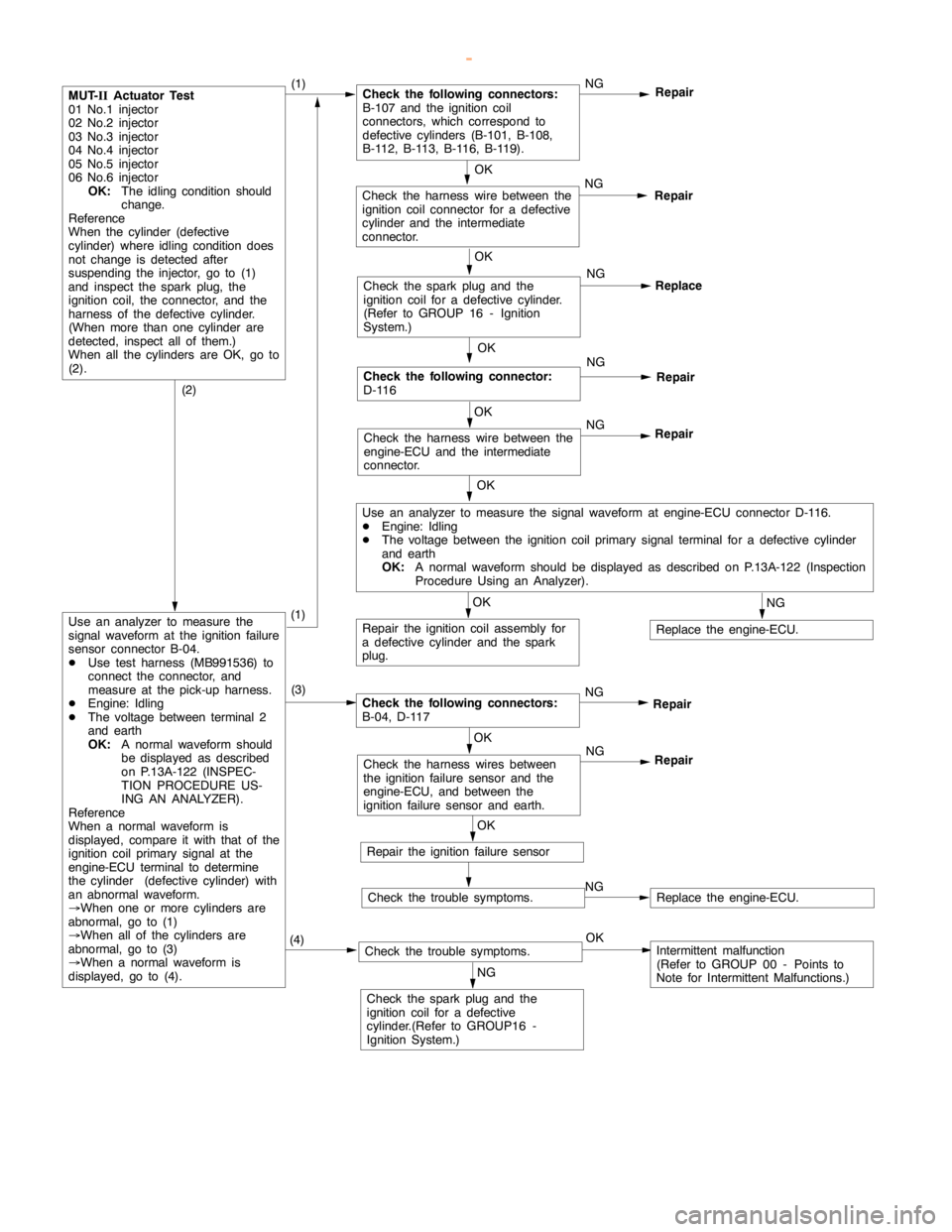
Check the harness wire between the
engine-ECU and the intermediate
connector.NG
Repair
OK
Check the following connector:
D-116NG
Repair
OK
Check the harness wire between the
ignition coil connector for a defective
cylinder and the intermediate
connector.NG
Repair
MUT-
IIActuator Test
01 No.1 injector
02 No.2 injector
03 No.3 injector
04 No.4 injector
05 No.5 injector
06 No.6 injector
OK:
The idling condition should
change.
Reference
When the cylinder (defective
cylinder) whereidling conditiondoes
not change is detected after
suspending the injector, go to (1)
and inspect the spark plug, the
ignition coil, the connector, and the
harness of the defective cylinder.
(When more than one cylinder are
detected, inspect all of them.)
When all the cylinders are OK, go to
(2).(1)Check the following connectors:
B-107 and the ignition coil
connectors, which correspond to
defective cylinders (B-101, B-108,
B-112, B-113, B-116, B-119).NG
Repair
OK
Check the sparkplug and the
ignition coil for a defective cylinder.
(Refer to GROUP 16 - Ignition
System.)NG
Replace
OK
Use an analyzer to measure the signal waveform at engine-ECU connector D-116.
DEngine: Idling
DThe voltage between the ignition coil primary signal terminal for a defective cylinder
and earth
OK:
A normal waveform should be displayed as described on P.13A-122 (Inspection
Procedure Using an Analyzer).
OK
Repair the ignition coil assembly for
a defective cylinder and the spark
plug.
NG
Replace the engine-ECU.
(2)
Use an analyzer to measure the
signal waveform at the ignition failure
sensor connector B-04.
DUse test harness (MB991536) to
connect the connector, and
measure at the pick-up harness.
DEngine: Idling
DThe voltage between terminal 2
and earth
OK:
A normal waveform should
be displayed as described
on P.13A-122 (INSPEC-
TION PROCEDURE US-
ING AN ANALYZER).
Reference
When a normal waveform is
displayed, compare it with that of the
ignition coil primary signal at the
engine-ECU terminal to determine
the cylinder (defective cylinder) with
an abnormal waveform.
®When one or more cylinders are
abnormal, go to (1)
®When all of the cylinders are
abnormal, go to (3)
®When a normal waveform is
displayed, go to (4).(3)
Check the following connectors:
B-04, D-117NG
Repair
OK
Check the harness wires between
the ignition failure sensor and the
engine-ECU, and between the
ignition failure sensor and earth.NG
Repair
OK
Repair the ignition failure sensor
Check the trouble symptoms.NGReplace the engine-ECU.
(4)Check the trouble symptoms.OKIntermittent malfunction
(Refer to GROUP 00 - Points to
Note for Intermittent Malfunctions.)
NG
Check the sparkplug and the
ignition coil for a defective
cylinder.(Refer to GROUP16 -
Ignition System.)
(1)
www.WorkshopManuals.co.uk
Purchased from www.WorkshopManuals.co.uk
Page 269 of 1839

GDI -Troubleshooting
Code No.P0301 No.1 cylinder misfire detected.
Code No.P0302 No.2 cylinder misfire detected.
Code No.P0303 No.3 cylinder misfire detected.
Code No.P0304 No.4 cylinder misfire detected.
Code No.P0305 No.5 cylinder misfire detected.Probable cause
Range of Check
DThe enginespeed is 500 - 4,500 r/min.
DWhile the engine is runningexcept deceleration and sudden acceleration.
Set Conditions
DThe number of misfires exceeds a predetermined number per 200engine
revolutions (Misfire has occurred in only one cylinder).
or
DThe number of misfires exceeds a predetermined number per 100engine
revolutions (Misfire has occurred in only one cylinder).DMalfunction of the ignition system
DAbnormal compression
DMalfunction of injector
DMalfunction of engine-ECU
NG
Check the harness wire between the
ignition coil and the engine-ECU.
NG
Replace
NG
Repair
(2) NG
OK
Check the ignition failure sensor
(Refer to GROUP 16 - Ignition
System.)
OK
Check the harness wire between the
ignition coil and the earth, and repair
if necessary. (3) NG
OK
Measure at ignition coil connectors
B-101, B-108, B-112, B-113, B-116,
B-119.
DDisconnect the connector and
measure at the harness side.
(1) The voltage between terminal 1
and earth
(Ignition switch: ON)
OK:
System voltage
(2) The voltage between terminal 3
and earth
(Engine: cranking)
OK:
0.5 - 4.0 V
(3) The resistance between terminal
2 and earth
OK:
2Wor less(1) NGCheck the following connectors:
B-04, B-107, D-208, D-223NG
Repair
Check the ignition coil (Refer to
GROUP 16 - Ignition System.)
Check the compression pressure.
(Refer to GROUP 11A - On-vehicle
Service.)Repair
Replace the engine-ECU.
OK
Check the harness wire between the
ignition coil and the ignition failure
sensor, and between the ignition coil
and the ignition failure sensor.
NG
Repair
OK
NGNG
Repair
OKReplace
NG
Check the spark plugs.
Check the trouble symptoms.
OK
Check the trouble symptoms.NGReplace the engine-ECU.
Check the following connectors:
B-101, B-108, B-112, B-113, B-116,
B-119
Check the following connector:
B-107, D-116
OK
www.WorkshopManuals.co.uk
Purchased from www.WorkshopManuals.co.uk
Page 274 of 1839
GDI -Troubleshooting
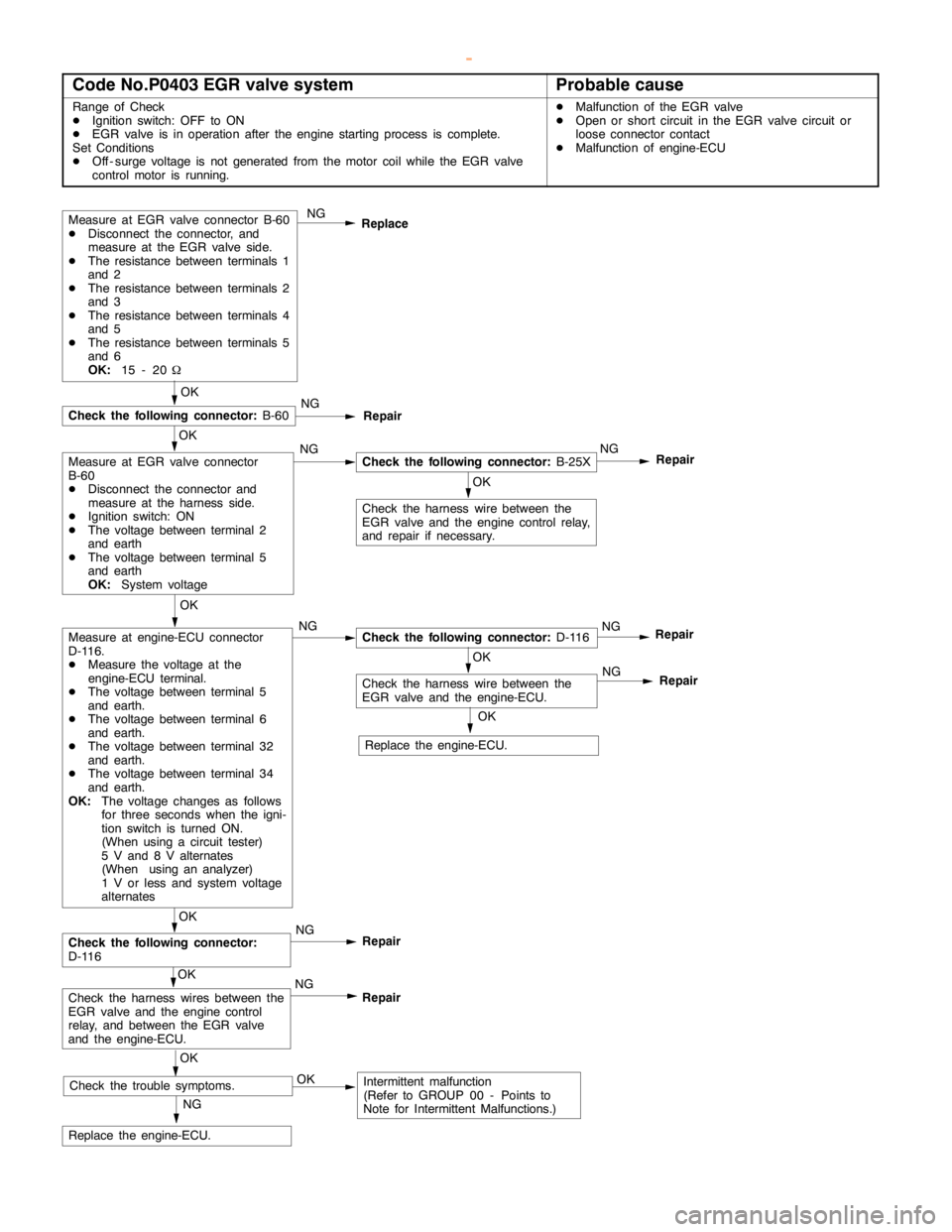
Code No.P0403 EGR valve systemProbable cause
Range of Check
DIgnition switch: OFF to ON
DEGR valve is in operation after theengine startingprocess is complete.
Set Conditions
DOff - surge voltage is not generated from the motor coil while the EGR valve
control motor is running.DMalfunction of the EGR valve
DOpen or short circuit in the EGR valve circuit or
loose connector contact
DMalfunction of engine-ECU
Measure at EGR valve connector B-60
DDisconnect the connector, and
measure at the EGR valve side.
DThe resistance between terminals 1
and 2
DThe resistance between terminals 2
and 3
DThe resistance between terminals 4
and 5
DThe resistance between terminals 5
and 6
OK:
15 - 20WNG
Replace
OK
Check the harness wire between the
EGR valve and theengine controlrelay,
and repair if necessary.
NG
Replace the engine-ECU.
OK
NG
Check the following connector:
B-25XNG
Repair
OK
Check the following connector:
B-60NG
Repair
OK
Measure at engine-ECU connector
D-116.
DMeasure the voltage at the
engine-ECU terminal.
DThe voltage between terminal 5
and earth.
DThe voltage between terminal 6
and earth.
DThe voltage between terminal 32
and earth.
DThe voltage between terminal 34
and earth.
OK:
The voltage changes as follows
for three seconds when the igni-
tion switch is turned ON.
(When using a circuit tester)
5 V and 8 V alternates
(When using an analyzer)
1 V or less and system voltage
alternatesNGCheck the following connector:
D-116NG
Repair
OK
Check the harness wire between the
EGR valve and the engine-ECU.
OK
Check the following connector:
D-116NG
Repair
OK
Check the harness wires between the
EGR valve and theengine control
relay, and between the EGR valve
and the engine-ECU.NG
Repair
OK
Check the trouble symptoms.OKIntermittent malfunction
(Refer to GROUP 00 - Points to
Note for Intermittent Malfunctions.)NG
Repair
OK
Replace the engine-ECU.
Measure at EGR valve connector
B-60
DDisconnect the connector and
measure at the harness side.
DIgnition switch: ON
DThe voltage between terminal 2
and earth
DThe voltage between terminal 5
and earth
OK:
System voltage
www.WorkshopManuals.co.uk
Purchased from www.WorkshopManuals.co.uk
Page 276 of 1839
GDI -Troubleshooting
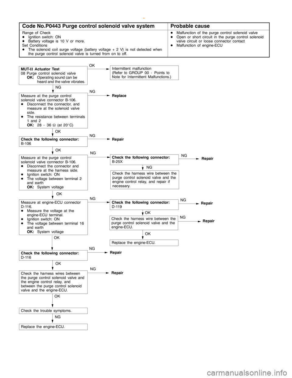
Code No.P0443 Purge control solenoid valve systemProbable cause
Range of Check
DIgnition switch: ON
DBattery voltage is 10 V or more.
Set Conditions
DThe solenoid coil surge voltage (battery voltage + 2 V) is not detected when
the purge control solenoid valve is turned from on to off.DMalfunction of the purge control solenoid valve
DOpen or short circuit in the purge control solenoid
valve circuit or loose connector contact
DMalfunction of engine-ECU
Repair
MUT-
IIActuator Test
08 Purge control solenoid valve
OK:
Operating sound can be
heard and the valve vibrates.OKIntermittent malfunction
(Refer to GROUP 00 - Points to
Note for Intermittent Malfunctions.)
NG
Check the harness wire between the
purge control solenoid valve and the
engine controlrelay, and repair if
necessary.
NG
Measure at the purge control
solenoid valve connector B-106.
DDisconnect the connector, and
measure at the solenoid valve
side.
DThe resistance between terminals
1 and 2
OK:
28 - 36W(at 20_C)NG
Replace
OK
Measure at the purge control
solenoid valve connector B-106.
DDisconnect the connector and
measure at the harness side.
DIgnition switch: ON
DThe voltage between terminal 2
and earth
OK:
System voltageNGCheck the following connector:
B-25XNG
Repair
OK
Check the following connector:
B-106NG
Repair
OK
OK
Measure at engine-ECU connector
D-116.
DMeasure the voltage at the
engine-ECU terminal.
DIgnition switch: ON
DThe voltage between terminal 16
and earth
OK:
System voltageNGCheck the following connector:
D-119NG
Repair
OK
Check the following connector:
D-116NG
Repair
OK
NG
Repair
OK
Check the trouble symptoms.
NG
Replace the engine-ECU.OKNG
Replace the engine-ECU.
Check the harness wires between
the purge control solenoid valve and
the engine controlrelay, and
between the purge control solenoid
valve and the engine-ECU.
Check the harness wire between the
purge control solenoid valve and the
engine-ECU.
www.WorkshopManuals.co.uk
Purchased from www.WorkshopManuals.co.uk
Page 291 of 1839
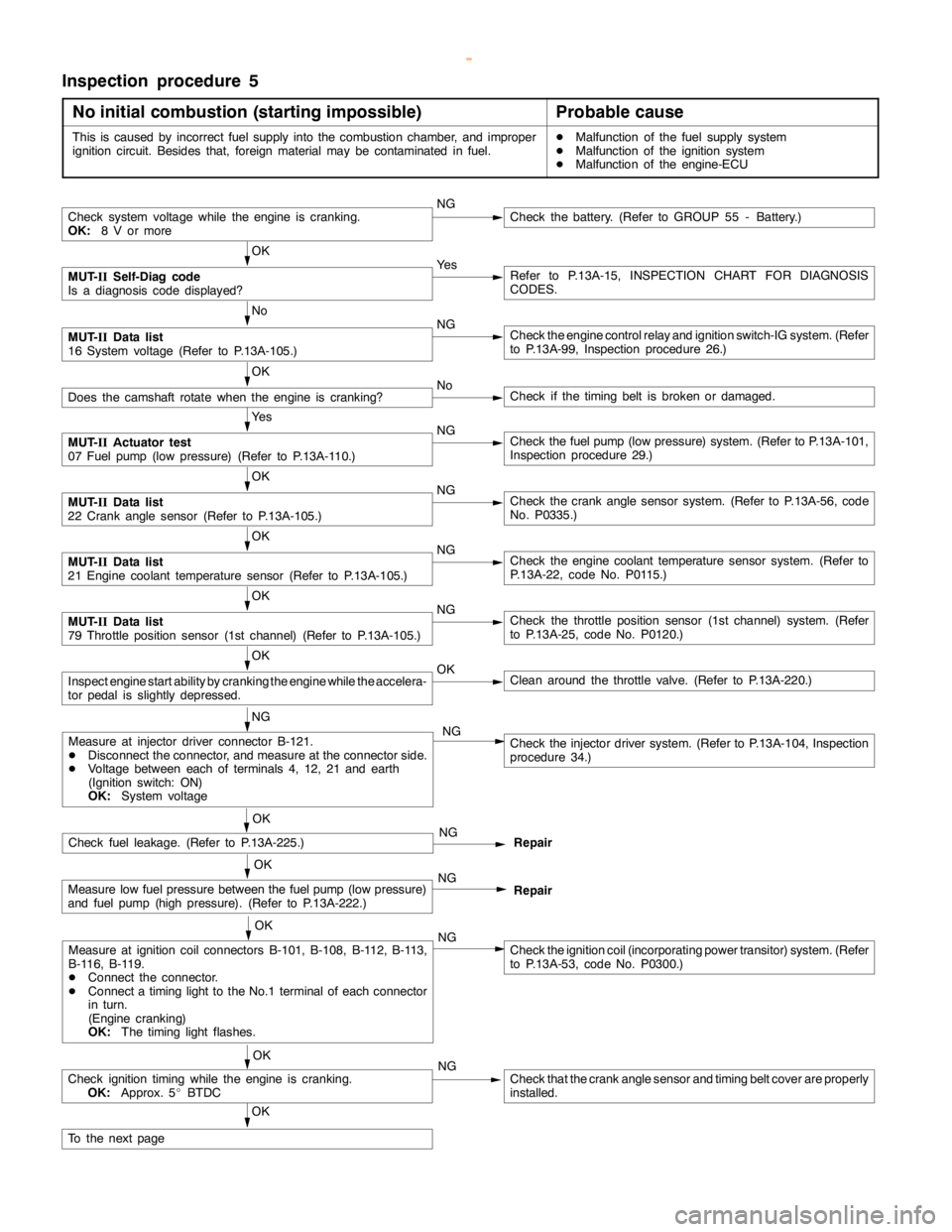
GDI -Troubleshooting
Inspection procedure 5
No initial combustion (starting impossible)
Probable cause
This is caused by incorrect fuel supply into the combustion chamber, and improper
ignition circuit. Besides that, foreign material may be contaminated in fuel.DMalfunction of the fuel supply system
DMalfunction of the ignition system
DMalfunction of the engine-ECU
Check system voltage while theengine iscranking.
OK:
8 V or moreNGCheck the battery. (Refer to GROUP 55 - Battery.)
OK
MUT-
IISelf-Diag code
Is a diagnosis code displayed?Ye sRefer to P.13A-15, INSPECTION CHART FOR DIAGNOSIS
CODES.
No
MUT-
IIData list
16 System voltage (Refer to P.13A-105.)NGCheck theengine controlrelay and ignition switch-IG system. (Refer
to P.13A-99, Inspection procedure 26.)
OK
Does the camshaft rotate when theengine is cranking?NoCheck if thetiming belt isbroken ordamaged.
Ye s
MUT-
IIActuator test
07 Fuel pump(low pressure) (Refer to P.13A-110.)NGCheck the fuelpump(low pressure) system. (Refer to P.13A-101,
Inspection procedure 29.)
OK
MUT-
IIData list
22 Crankanglesensor (Refer to P.13A-105.)NGCheck the crankanglesensor system. (Refer to P.13A-56, code
No. P0335.)
OK
MUT-
IIData list
21 Engine coolant temperature sensor (Refer to P.13A-105.)NGCheck theengine coolant temperaturesensor system. (Refer to
P.13A-22, code No. P0115.)
OK
MUT-
IIData list
79 Throttle position sensor (1st channel) (Refer to P.13A-105.)NGCheck the throttle position sensor (1st channel) system. (Refer
to P.13A-25, code No. P0120.)
OK
Inspectenginestart ability by cranking theengine while theaccelera-
tor pedal isslightly depressed.OKClean around the throttle valve. (Refer to P.13A-220.)
NG
Check fuel leakage. (Refer to P.13A-225.)NG
Repair
OK
Measure low fuel pressure between the fuelpump(low pressure)
and fuel pump (highpressure). (Refer to P.13A-222.)NG
Repair
OK
Measure at ignition coil connectors B-101, B-108, B-112, B-113,
B-116, B-119.
DConnect the connector.
DConnect atiming light to theNo.1 terminal of each connector
in turn.
(Engine cranking)
OK:
The timing lightflashes.NGCheck the ignition coil (incorporating power transitor) system. (Refer
to P.13A-53, code No. P0300.)
OK
Check ignitiontiming while the engine iscranking.
OK:
Approx. 5_BTDCNGCheck that the crankanglesensor andtiming beltcover are properly
installed.
OK
To the nextpage
Measure at injector driver connector B-121.
DDisconnect the connector, and measure at the connector side.
DVoltage between each of terminals 4, 12, 21 and earth
(Ignition switch: ON)
OK:
System voltageCheck the injector driver system. (Refer to P.13A-104, Inspection
procedure 34.) NG
OK
www.WorkshopManuals.co.uk
Purchased from www.WorkshopManuals.co.uk
Page 292 of 1839
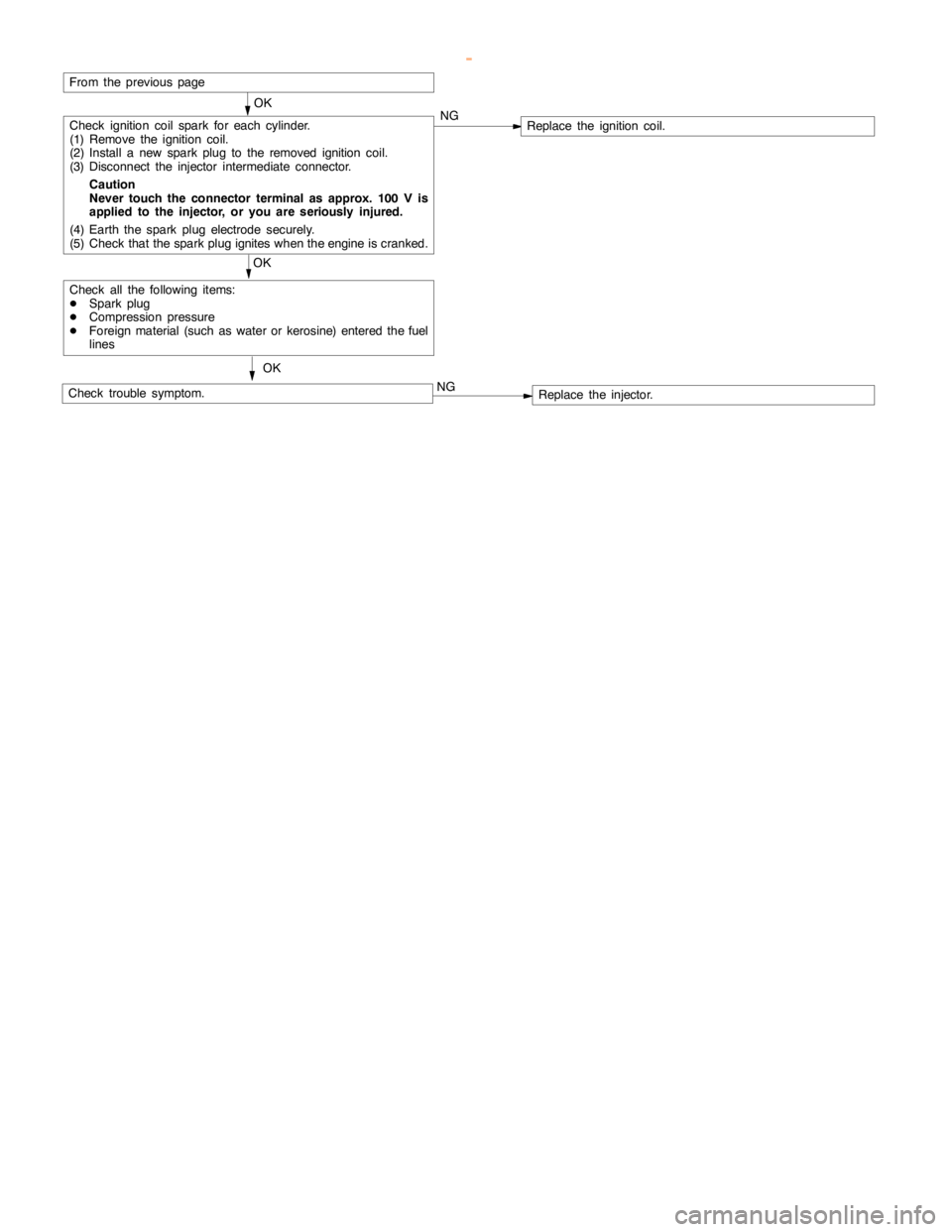
GDI -Troubleshooting
OK
Check ignition coil spark for each cylinder.
(1) Remove the ignition coil.
(2) Install a new sparkplug to the removed ignitioncoil.
(3) Disconnect the injector intermediate connector.
Caution
Never touch the connector terminal as approx. 100 V is
applied to the injector, or you are seriously injured.
(4) Earth the sparkplug electrodesecurely.
(5) Check that the sparkplug igniteswhen theengine iscranked.NGReplace the ignition coil.
OK
Check all the following items:
DSparkplug
DCompression pressure
DForeign material (such as water or kerosine) entered the fuel
lines
Check trouble symptom.OKNGReplace the injector.
From the previouspage
www.WorkshopManuals.co.uk
Purchased from www.WorkshopManuals.co.uk
Page 294 of 1839
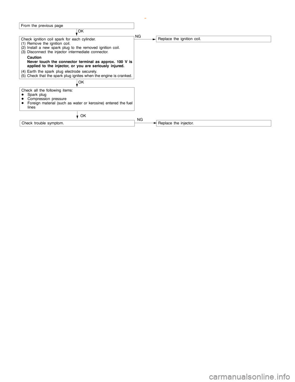
GDI -Troubleshooting
OK
Check ignition coil spark for each cylinder.
(1) Remove the ignition coil.
(2) Install a new sparkplug to the removed ignitioncoil.
(3) Disconnect the injector intermediate connector.
Caution
Never touch the connector terminal as approx. 100 V is
applied to the injector, or you are seriously injured.
(4) Earth the sparkplug electrodesecurely.
(5) Check that the sparkplug igniteswhen theengine iscranked.NGReplace the ignition coil.
OK
Check all the following items:
DSparkplug
DCompression pressure
DForeign material (such as water or kerosine) entered the fuel
lines
Check trouble symptom.OKNGReplace the injector.
From the previouspage
www.WorkshopManuals.co.uk
Purchased from www.WorkshopManuals.co.uk