2000 MITSUBISHI MONTERO sensor
[x] Cancel search: sensorPage 1210 of 1839

35A-2
BASIC BRAKE
SYSTEM
CONTENTS
GENERAL INFORMATION 3..................
SERVICE SPECIFICATIONS 5.................
LUBRICANTS 6..............................
SPECIAL TOOLS 6..........................
TROUBLESHOOTING
ON-VEHICLE SERVICE 19...................
Brake Pedal Check and Adjustment 19..........
Hydraulic Brake Booster (HBB) Operation Check
HBB Check
HBB Motor Relay Continuity Check
Brake Booster Operating Test
Check Valve Operation Check
Load Sensing Spring Length Check and
Adjustment
Load Sensing Proportioning Valve Function
Test
Bleeding
Brake Fluid Level Sensor Check 30.............
Brake Booster Vacuum Switch Check
Disc Brake Pad Check and Replacement 31.....
Disc Brake Rotor Check 32.....................
Brake Disc Thickness Check 32.................
Brake Disc Run-out Check and Correction 33....
BRAKE PEDAL 34..........................
HYDRAULIC BRAKE BOOSTER (HBB)
HBB BUZZER
MASTER CYLINDER AND BRAKE
BOOSTER
Master Cylinder 43.............................
FRONT DISC BRAKE 44....................
REAR DISC BRAKE 49......................
LOAD SENSING PROPORTIONING
VALVE
www.WorkshopManuals.co.uk
Purchased from www.WorkshopManuals.co.uk
Page 1264 of 1839

35B-1
ANTI-SKID
BRAKING SYSTEM
(ABS) <4WD>
CONTENTS
GENERAL INFORMATION 2..................
SERVICE SPECIFICATIONS 4.................
LUBRICANT Refer to GROUP 35A...........
SEALANTS Refer to GROUP 35A............
SPECIAL TOOLS 4..........................
TROUBLESHOOTING 4.......................
ON-VEHICLE SERVICE 27...................
Wheel Speed Sensor Output Voltage
Measurement 27...............................
ABS Valve Relay Continuity Check 28...........
Hydraulic Brake Booster (HBB) - Hydraulic Unit
Check 29......................................
Solenoid Valve Check 30.......................
When the Battery is Flat 31....................
Brake Pedal Check and Adjustment
Refer to GROUP 35A ..........................
Hydraulic Brake Booster (HBB) Operation Check
Refer to GROUP 35A ..........................
Hydraulic Brake Booster (HBB) Check
Refer to GROUP 35A ..........................Motor Relay Continuity Check
Refer to GROUP 35A ..........................
Bleeding Refer to GROUP 35A..................
Brake Fluid Level Sensor Check
Refer to GROUP 35A ..........................
Disc Brake Pad Check and Replacement
Refer to GROUP 35A ..........................
Brake Disc Thickness Check
Refer to GROUP 35A ..........................
Brake Disc Runout Check and Correction
Refer to GROUP 35A ..........................BRAKE PEDAL Refer to GROUP 35A........
HYDRAULIC BRAKE BOOSTER (HBB)
Refer to GROUP 35A ........................
HBB BUZZER Refer to GROUP 35A..........
FRONT DISC BRAKE Refer to GROUP 35A..
REAR DISC BRAKE Refer to GROUP 35A....
ABS-ECU 32................................
WHEEL SPEED SENSOR 33.................
G-SENSOR 36..............................
www.WorkshopManuals.co.uk
Purchased from www.WorkshopManuals.co.uk
Page 1265 of 1839

ABS <4WD> -General Information35B-2
GENERAL INFORMATION
ABS has been adopted as standard equipment
in all vehicles to maintain directional stability and
steering performance during sudden braking.
The ABS control method used is a 4-sensor,
4-channel method (previous models: 4-sensor,
3- channel method
)which allows the brake
pressures for all four wheels to be controlled
independently of each other. The system has the
following features.
DEBD
*(Electronic Brake force Distribution
system) control has been added to provide the
ideal braking force for the rear wheels.DThe hydraulic unit function has been integrated
with the hydraulic brake booster (HBB).
DSelect solenoid valves (two valves for FL and
FR) have been adopted in order to reduce the
pedal kickback and improve the operation
feeling when the ABS is operating.
DIndependent 4-wheel control is carried out wile
the vehicle is turning in order to increase the
braking force.
NOTE
*EBD: Electronic Brake-force Distribution
EBD CONTROL
In ABS, electronic control method is used whereby
the rear wheel brake hydraulic pressure during
braking is regulated by rear wheel control solenoid
valves in accordance with the vehicle’s rate of
deceleration and the front and rear wheel slippage
which are calculated from the signals received from
the various wheel sensors. EBD control is a control
system which provides a high level of control for
both vehicle braking force and vehicle stability. The
system has the following features.
DBecause the system provides the optimum rear
wheel braking force regardless of the vehicle
laden condition and the condition of the road
surface, the system reduces the required pedal
depression force, particularly when the vehicle
is heavily laden or driving on road surfaces
with high frictional coefficients.DBecause the duty placed on the front brakes
has been reduced, the increases in pad
temperature can be controlled during front
brakes applying to improve the wear resistance
characteristics of the pad.
DControl valves such as the proportioning valve
are no longer required.
SPECIFICATIONS
ItemSpecifications
ABS control method4-sensor, 4-channel
No. of ABS rotor teethFront50
Rear50
ABS speed sensorTypeMagnet coil type
Gap between sensor and rotor mm0.9 (non-adjustable type)
www.WorkshopManuals.co.uk
Purchased from www.WorkshopManuals.co.uk
Page 1270 of 1839

ABS <4WD> -Troubleshooting35B-7
INSPECTION CHART FOR DIAGNOSIS CODES
Diagnosis code
No.Diagnosis itemReference page
11Wheel speed sensor (FR) system (open circuit or short - circuit)35B-8
12Wheel speed sensor (FL) system (open circuit or short - circuit)35B-8
13Wheel speed sensor (RR) system (open circuit or short - circuit)35B-8
14Wheel speed sensor (RL) system (open circuit or short - circuit)35B-8
15Wheel speed sensor system (output signal abnormality)35B-9
16ABS-ECU or valve relay power supply system (abnormal voltage
drop or rise)35B-10
21Wheel speed sensor (FR) system35B-8
22Wheel speed sensor (FL) system35B-8
23Wheel speed sensor (RR) system35B-8
24Wheel speed sensor (RL) system35B-8
26Center differential lock switch system35B-11, 12
27Rear differential lock switch system35B-11, 12
32G sensor system35B-13
33Stop lamp switch system35B-14
41Control solenoid valve (FR)
systemIf there is no response to the
solenoid valve drive signal35B-15
42Control solenoid valve (FL)
systemcorresponding to each respec-
tive item
43Control solenoid valve (RR)
system
44Control solenoid valve (RL)
system
45Changeover solenoid valve
(FR) system
46Changeover solenoid valve
(FL) system
51Valve relay system (ON problem)35B-16
52Valve relay system(OFFproblem)35B-17
55HBB systemCarry out HBB troubleshoot-
ing. (Refer to GROUP 35A.)
63ABS-ECU system35B-32 (ABS-ECU replace-
ment)
NOTE
*: Code No.16 is erased from the memory if the condition returns to normal.
www.WorkshopManuals.co.uk
Purchased from www.WorkshopManuals.co.uk
Page 1271 of 1839

ABS <4WD> -TroubleshootingABS <4WD> -Troubleshooting35B-8
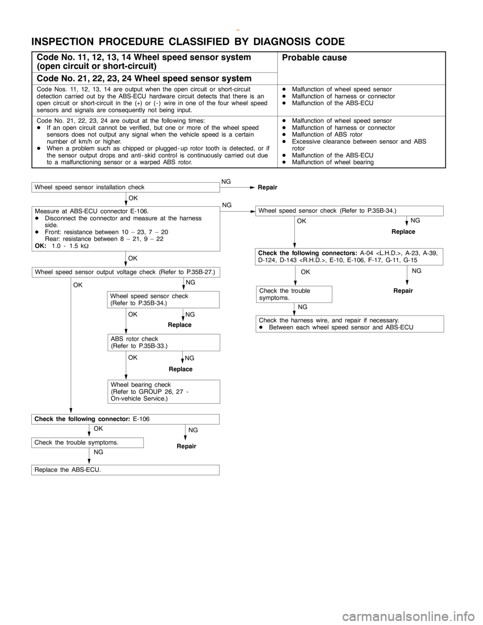
INSPECTION PROCEDURE CLASSIFIED BY DIAGNOSIS CODE
Code No. 11, 12, 13, 14 Wheel speed sensor system
(open circuit or short-circuit)Probable cause
Code No. 21, 22, 23, 24 Wheel speed sensor system
Code Nos. 11, 12, 13, 14 are output when theopencircuit or short-circuit
detection carried out by the ABS-ECU hardware circuit detects that there is an
opencircuit or short-circuit in the (+) or ( - ) wire in one of the four wheel speed
sensors and signals are consequently notbeing input.DMalfunction of wheel speed sensor
DMalfunction of harness or connector
DMalfunction of the ABS-ECU
Code No. 21, 22, 23, 24 are output at the following times:
DIf an opencircuit cannot be verified, but one or more of the wheel speed
sensors does not output any signal when the vehicle speed is a certain
number of km/h or higher.
DWhen a problem such as chipped orplugged - uprotor tooth is detected, or if
the sensor output drops and anti - skid control is continuously carried out due
to a malfunctioning sensor or a warped ABS rotor.DMalfunction of wheel speed sensor
DMalfunction of harness or connector
DMalfunction of ABS rotor
DExcessive clearancebetween sensor and ABS
rotor
DMalfunction of the ABS-ECU
DMalfunction of wheel bearing
NG
NG
Replace the ABS-ECU.
NG
Repair
OK
Check the trouble symptoms.
OK
Check the following connector:E-106
OK
Wheel bearing check
(Refer to GROUP 26, 27 -
On-vehicle Service.)
NG
Replace
OK
ABS rotor check
(Refer to P.35B-33.)
NG
Replace
Wheel speed sensor check
(Refer to P.35B-34.)
OK
Wheel speed sensor output voltage check (Refer to P.35B-27.)
OK
Check the following connectors:A-04
D-124, D-143
Wheel speed sensor installation checkNG
Repair
OK
Measure at ABS-ECU connector E-106.
DDisconnect the connector and measure at the harness
side.
DFront: resistance between 10 – 23, 7 – 20
Rear: resistance between 8 – 21, 9 – 22
OK:1.0 - 1.5 k
WNG
NG
Replace
NG
Repair
OK
Check the trouble
symptoms.
NG
Check the harness wire, and repair if necessary.
DBetween each wheel speed sensor and ABS-ECU
Wheel speed sensor check (Refer to P.35B-34.)
www.WorkshopManuals.co.uk
Purchased from www.WorkshopManuals.co.uk
Page 1272 of 1839

ABS <4WD> -Troubleshooting35B-9
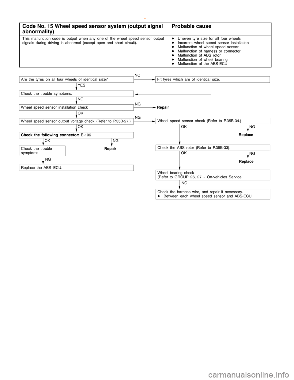
Code No. 15 Wheel speed sensor system (output signal
abnormality)Probable cause
This malfunction code is output when any one of the wheel speed sensor output
signals during driving is abnormal (exceptopen andshort circuit).DUneven tyre size for all four wheels
DIncorrect wheel speed sensor installation
DMalfunction of wheel speed sensor
DMalfunction of harness or connector
DMalfunction of ABS rotor
DMalfunction of wheel bearing
DMalfunction of the ABS-ECU
NG
Check the harness wire, and repair if necessary.
DBetween each wheel speed sensor and ABS-ECU
OK
Wheel bearing check
(Refer to GROUP 26, 27 - On-vehicles Service.
NG
Replace
OKNG
Replace
NG
Replace the ABS - ECU.
OK
Check the trouble
symptoms.
NG
Repair
OK
Check the following connector:E-106
OK
Wheel speed sensor output voltage check (Refer to P.35B-27.)NGWheel speed sensor check (Refer to P.35B-34.)
NG
Wheel speed sensor installation checkNG
Repair
Are the tyres on all four wheels of identical size?NOFit tyres which are of identical size.
YES
Check the trouble symptoms.
Check the ABS rotor (Refer to P.35B-33).
www.WorkshopManuals.co.uk
Purchased from www.WorkshopManuals.co.uk
Page 1284 of 1839

ABS <4WD> -Troubleshooting35B-21
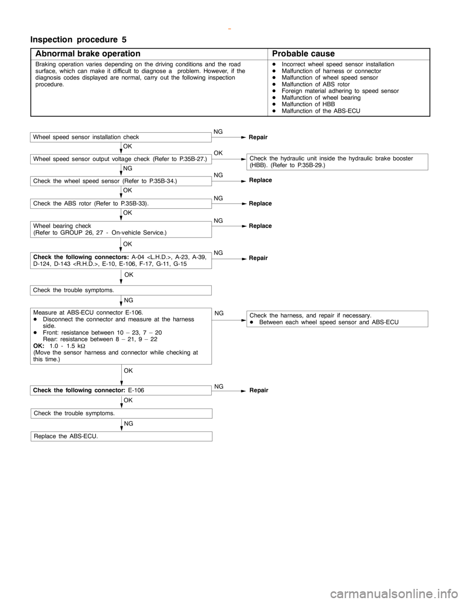
Inspection procedure 5
Abnormal brake operation
Probable cause
Braking operation variesdepending on the driving conditions and the road
surface, which can make it difficult to diagnose a problem. However, if the
diagnosis codes displayed are normal, carry out the following inspection
procedure.DIncorrect wheel speed sensor installation
DMalfunction of harness or connector
DMalfunction of wheel speed sensor
DMalfunction of ABS rotor
DForeign material adhering to speed sensor
DMalfunction of wheel bearing
DMalfunction of HBB
DMalfunction of the ABS-ECU
Wheel speed sensor installation checkNG
Repair
OKCheck the hydraulic unit inside the hydraulic brake booster
(HBB). (Refer to P.35B-29.)
NG
Check the wheel speed sensor (Refer to P.35B-34.)NG
OK
Check the ABS rotor (Refer to P.35B-33).NG
Replace
OK
NG
Replace
OK
NG
Repair
OK
NG
NG
OK
Check the following connector:E-106
OK
Check the trouble symptoms.
NG
Replace the ABS-ECU.NG
Repair
Check the harness, and repair if necessary.
DBetween each wheel speed sensor and ABS-ECU ReplaceMeasure at ABS-ECU connector E-106.
DDisconnect the connector and measure at the harness
side.
DFront: resistance between 10 – 23, 7 – 20
Rear: resistance between 8 – 21, 9 – 22
OK:1.0 - 1.5 k
W
(Move the sensor harness and connector while checking at
this time.)
Check the following connectors:A-04
D-124, D-143
Wheel bearing check
(Refer to GROUP 26, 27 - On-vehicle Service.)
Check the trouble symptoms.
Wheel speed sensor output voltage check (Refer to P.35B-27.)OK
www.WorkshopManuals.co.uk
Purchased from www.WorkshopManuals.co.uk
Page 1285 of 1839

ABS <4WD> -Troubleshooting35B-22
DATA LIST REFERENCE TABLE
The following ECU input data items can be read using the MUT-II
.
(1) When system is normal
Item
No.Check itemInspection conditionsNormal condi-
tion
11Front - right wheel
speedWhen vehicle is being drivenSpeedometer
display and
12Front - left wheel
speedMUT-IIdisplay
are identical.
13Rear - right wheel
speed
14Rear - left wheel
speed
16System voltageIgnition switch: ON6.5 - 22.3 V
26Center differential
lock switchIgnition switch: ONTransfer selector lever position:
2H, 4HOFF
Transfer selector lever position:
4HLc, 4LLcON
27Rear differential lock
switchIgnition switch: ONOFF
32G sensorD
Ignition switch: ON
D
When vehicle is stationary (level)2.4 - 2.6 V
When vehicle is being driven1.0 - 4.0 V
33Stop lampIgnition switch: ONWhen brake pedal is depressedON
SwitchWhen brake pedal is releasedOFF
(2) When system is interrupted by the ECU
When the diagnosis function has caused the operation of the ABS-ECU to be stopped, the
MUT-II
display data may be different from the actual condition.
ACTUATOR TEST TABLE
The following actuators can be force-driven using the MUT-II
.
NOTE
(1) Actuator tests cannot be carried out when the operation of the ABS-ECU has been stopped by
the fail-safe function.
(2) Actuator tests can only be carried out while the vehicle is stopped.
ACTUATOR TEST SPECIFICATIONS
Item No.Check itemDrive Contents
01FR wheel solenoid valveHBB select solenoid valves and control solenoid valves for the
02FL wheel solenoid valverespective channel
03RR wheel solenoid valve
04RL wheel solenoid valve
27Air bleeding (1)HBB select solenoid valves and control solenoid valve OUT (FR, FL)
28Air bleeding (2)HBB control solenoid valve OUT (RR, RL)
www.WorkshopManuals.co.uk
Purchased from www.WorkshopManuals.co.uk