2000 MITSUBISHI MONTERO sensor
[x] Cancel search: sensorPage 1457 of 1839

52A-2
INTERIOR
CONTENTS
SERVICE SPECIFICATIONS 3.................
SPECIAL TOOL 3............................
INSTRUMENT PANEL
INSTRUMENT PANEL
FLOOR CONSOLE 12........................
TRIMS 13...................................
SUNVISOR HOLDER 17......................FRONT SEAT 18............................
REAR/SECOND SEAT 25....................
THIRD SEAT 35.............................
FRONT SEAT BELT 38.......................
REAR SEAT BELT
SECOND/THIRD SEAT BELT
WARNINGS REGARDING SERVICING OF SUPPLEMENTAL RESTRAINT SYSTEM (SRS) EQUIPPED VEHICLES
WARNING!
(1) Improper service or maintenance of any component of the SRS, or any SRS-related component, can lead to personal
injury or death to service personnel (from inadvertent firing of the air bag) or to the driver (from rendering the SRS
inoperative).
(2) Service or maintenance of any SRS component or SRS-related component must be performed only at an authorized
MITSUBISHI dealer.
(3) MITSUBISHI dealer personnel must thoroughly review this manual, and especially its GROUP 52B - Supplemental
Restraint System (SRS) before beginning any service or maintenance of any component of the SRS or any SRS-related
component.
NOTE
The SRS includes the following components: front impact sensors, SRS-ECU, SRS warning lamp, air bag module, clock spring and
interconnecting wiring. Other SRS-related components (that mayhave to be removed/installed in connectionwith SRS service or
maintenance) are indicated in the table of contents by an asterisk(*).
www.WorkshopManuals.co.uk
Purchased from www.WorkshopManuals.co.uk
Page 1501 of 1839

52B-1
SUPPLEMENTAL
RESTRAINT
SYSTEM (SRS)
CONTENTS
GENERAL INFORMATION 2..................
SRS SERVICE PRECAUTIONS 3..............
SPECIAL TOOLS 5..........................
TEST EQUIPMENT 6.........................
TROUBLESHOOTING 7.......................
SRS MAINTENANCE 19.....................
POST-COLLISION DIAGNOSIS 23............
INDIVIDUAL COMPONENT SERVICE 26......
WARNING/CAUTION LABELS 27.............FRONT IMPACT SENSORS 28...............
SRS AIR BAG CONTROL UNIT
(SRS-ECU) 30...............................
AIR BAG MODULES AND CLOCK
SPRING 32.................................
SIDE IMPACT SENSOR 41..................
AIR BAG MODULE DISPOSAL
PROCEDURES 43...........................
Undeployed Air Bag Module Disposal 43.........
Deployed Air Bag Module Disposal
Procedures 52.................................
CAUTION
DCarefully read and observe the information in the SERVICE PRECAUTIONS (P.52B-3.) prior to any service.
DFor information concerning troubleshooting or maintenance, always observe the procedures in the Troubleshooting
(P.52B-7.) section.
DIf any SRS components are removed or replaced in connection with any service procedures, be sure to follow the
procedures in the INDIVIDUAL COMPONENT SERVICE section (P.52B-26.) for the components involved.
DIf you have any questions about theSRS, please contact your local distributor.
www.WorkshopManuals.co.uk
Purchased from www.WorkshopManuals.co.uk
Page 1508 of 1839

SRS -Troubleshooting52B-8
Code No.Reference
page Diagnosis item
43*1SRS warning lamp drive circuit systemLamp does not illuminate.52B-14
Lamp does not go out off.52B-14
44*1SRS warning lamp drive circuit system52B-14
45Internal circuit system of non-volatile memory (EEPROM) inside SRS-ECU52B-9
51, 52Driver’s air bag module (squib) system52B-9
54, 55Passenger’s air bag module (squib) system52B-9
71*2,72*2, 75, 76Side air bag module (R.H.) (squib) system52B-15
73, 74Side air bag module (R.H.) (squib) system52B-9
79, 93Side impact sensor (L.H.) communication system52B-16
81*2,82*2, 85, 86Side air bag module (L.H.) (squib) system52B-16
83, 84Side air bag module (L.H.) (squib ignition drive circuit) system52B-9
89, 96Side impact sensor (R.H.) communication system52B-17
91*1Side impact sensor (L.H.) power supply circuit system52B-17
92Analog G-sensor system inside side impact sensor52B-17
94*1Side impact sensor (R.H.) power supply circuit52B-18
95Analog G-sensor system inside side impact sensor (R.H.)52B-17
NOTE
1. *1: If the trouble(s) are extinguished, the SRS warning lamp will go out with diagnosis code history
automatically erased.
2. *2: If the vehicle condition return to normal, the diagnosis code will be automatically erased, and
the SRS warning lamp will return to normal.
3. If the vehicle has a discharged battery, it will store the fault codes 41 or 42. When these diagnosis
codes are displayed, check the battery.
INSPECTION PROCEDURE CLASSIFIED BY DIAGNOSIS CODE
Code No.11, 12 or 13 Front impact sensor systemProbable cause
These diagnosis codes are output if there is abnormal resistance between the
input terminals of the front impact sensors inside the SRS-ECU.
The trouble causes for each diagnosis code No. are as follow.DMalfunction of harness or connector
DMalfunction of front impact sensor
DMalfunction of SRS-ECU
Table 1
Code No.Trouble Symptom
11D
Short circuit in front impact sensor or harness
D
Short circuit in front impact sensor harness leading to the vehicle body ground
D
Short circuit in front impact sensor harness leading to the power supply
12D
Open circuit in either left or right front impact sensor or harness
D
Short circuit in front impact sensor harness leading to the power supply
13D
Open circuit in both left and right front impact sensor or harness
D
Short circuit in front impact sensor harness leading to the power supply
www.WorkshopManuals.co.uk
Purchased from www.WorkshopManuals.co.uk
Page 1509 of 1839

SRS -Troubleshooting52B-9
OK
Check the trouble symptoms.
NG
Repair
OK
Replace the SRS-ECU.
Measure at SRS-ECU connector E-111.
DDisconnect the connector and measure at the harness
side.
DResistances between terminal 1 and 2, 3 and 4
NG:2
Wor less (short circuit)
NG:1M
Wor more (open circuit)
DContinuity between 1, 2, 3, 4 and body earth
OK: No continuityNGCheck the following connector:A-31, A-25, D-27, E-111
NG
Check the harness wire between the front impact sensor and
the SRS-ECU, and repair if necessary.
OK
Check the front impact sensor (Refer to P.52B-21.)
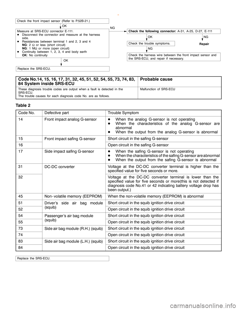
Code No.14, 15, 16, 17, 31, 32, 45, 51, 52, 54, 55, 73, 74, 83,
84 System inside SRS-ECUProbable cause
These diagnosis trouble codes are output when a fault is detected in the
SRS-ECU.
The trouble causes for each diagnosis code No. are as follows.Malfunction of SRS-ECU
Table 2
Code No.Defective partTrouble Symptom
14Front impact analog G-sensorD
When the analog G-sensor is not operating
D
When the characteristics of the analog G-sensor are
abnormal
D
When the output from the analog G-sensor is abnormal
15Front impact safing G-sensorShort circuit in the safing G-sensor
16Open circuit in the safing G-sensor
17Side impact safing G-sensorD
When the safing G-sensor is not operating
D
When the characteristics of the safing G-sensor are abnormal
D
When the output from the safing G-sensor is abnormal
31DC-DC converterVoltage at the DC-DC converter terminal is higher than the
specified value for five seconds or more.
32Voltage at the DC-DC converter terminal is lower than the
specified value for five seconds or more(this is not detected if
diagnosis code No.41 or 42 indicating battery voltage drop has
been output.)
45Non - volatile memory (EEPROM)When the non-volatile memory (EEPROM) is abnormal
51Driver’s side air bag moduleShort circuit in the squib ignition drive circuit
52(squib)Open circuit in the squib ignition drive circuit
54Passenger’s air bag moduleShort circuit in the squib ignition drive circuit
55(squib)Open circuit in the squib ignition drive circuit
73Side air bag module (R.H.) (squib)Short circuit in the squib ignition drive circuit
74Open circuit in the squib ignition drive circuit
83Side air bag module (L.H.) (squib)Short circuit in the squib ignition drive circuit
84Open circuit in the squib ignition drive circuit
Replace the SRS-ECU.
www.WorkshopManuals.co.uk
Purchased from www.WorkshopManuals.co.uk
Page 1517 of 1839

SRS -Troubleshooting52B-17
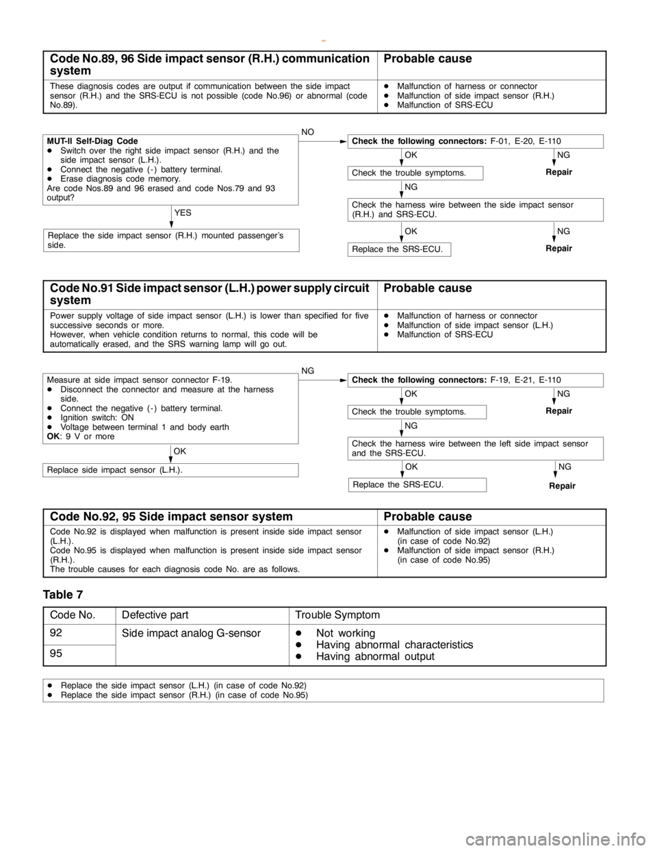
Code No.89, 96 Side impact sensor (R.H.) communication
systemProbable cause
These diagnosis codes are output if communication between the side impact
sensor (R.H.) and the SRS-ECU is not possible (code No.96) or abnormal (code
No.89).DMalfunction of harness or connector
DMalfunction of side impact sensor (R.H.)
DMalfunction of SRS-ECU
OK
Check the trouble symptoms.
NG
Repair
NG
RepairOK
Replace the SRS-ECU.
YES
Replace the side impact sensor (R.H.) mounted passenger’s
side.
MUT-II Self-Diag Code
DSwitch over the right side impact sensor (R.H.) and the
side impact sensor (L.H.).
DConnect the negative ( - ) battery terminal.
DErase diagnosis code memory.
Are code Nos.89 and 96 erased and code Nos.79 and 93
output?NOCheck the following connectors:F-01, E-20, E-110
NG
Check the harness wire between the side impact sensor
(R.H.) and SRS-ECU.
Code No.91 Side impact sensor (L.H.) power supply circuit
systemProbable cause
Power supply voltage of side impact sensor (L.H.) is lower than specified for five
successive seconds ormore.
However, when vehicle condition returns to normal, this code will be
automatically erased, and the SRS warning lampwill go out.DMalfunction of harness or connector
DMalfunction of side impact sensor (L.H.)
DMalfunction of SRS-ECU
Measure at side impact sensor connector F-19.
DDisconnect the connector and measure at the harness
side.
DConnect the negative ( - ) battery terminal.
DIgnition switch: ON
DVoltage between terminal 1 and body earth
OK: 9 V or moreNGCheck the following connectors:F-19, E-21, E-110
OK
Check the trouble symptoms.
NG
Repair
NG
Check the harness wire between the left side impact sensor
and the SRS-ECU.
NG
RepairOK
Replace the SRS-ECU.
OK
Replace side impact sensor (L.H.).
Code No.92, 95 Side impact sensor systemProbable cause
Code No.92 is displayed when malfunction is present inside side impact sensor
(L.H.).
Code No.95 is displayed when malfunction is present inside side impact sensor
(R.H.).
The trouble causes for each diagnosis code No. are as follows.DMalfunction of side impact sensor (L.H.)
(in case of code No.92)
DMalfunction of side impact sensor (R.H.)
(in case of code No.95)
Table 7
Code No.Defective partTrouble Symptom
92Side impact analog G-sensorD
Not working
95D
Having abnormal characteristics
D
Having abnormal output
DReplace the side impact sensor (L.H.) (in case of code No.92)
DReplace the side impact sensor (R.H.) (in case of code No.95)
www.WorkshopManuals.co.uk
Purchased from www.WorkshopManuals.co.uk
Page 1518 of 1839

SRS -Troubleshooting52B-18
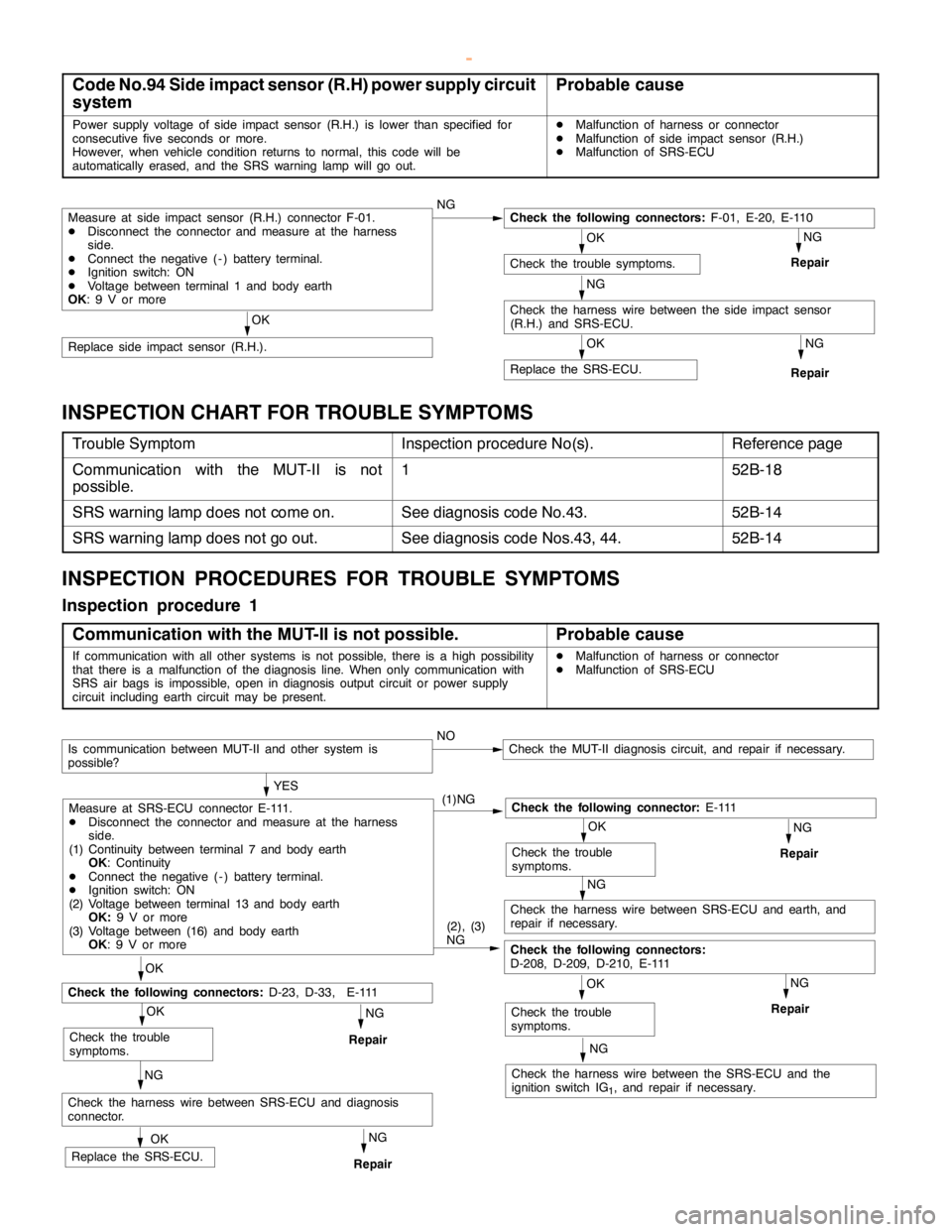
Code No.94 Side impact sensor (R.H) power supply circuit
systemProbable cause
Power supply voltage of side impact sensor (R.H.) is lower than specified for
consecutive five seconds or more.
However, when vehicle condition returns to normal, this code will be
automatically erased, and the SRS warning lampwill go out.DMalfunction of harness or connector
DMalfunction of side impact sensor (R.H.)
DMalfunction of SRS-ECU
Measure at side impact sensor (R.H.) connector F-01.
DDisconnect the connector and measure at the harness
side.
DConnect the negative ( - ) battery terminal.
DIgnition switch: ON
DVoltage between terminal 1 and body earth
OK: 9 V or moreNGCheck the following connectors:F-01, E-20, E-110
OK
Check the trouble symptoms.
NG
Repair
NG
Check the harness wire between the side impact sensor
(R.H.) and SRS-ECU.
NG
RepairOK
Replace the SRS-ECU.
OK
Replace side impact sensor (R.H.).
INSPECTION CHART FOR TROUBLE SYMPTOMS
Trouble SymptomInspection procedure No(s).Reference page
Communication with the MUT-II is not
possible.152B-18
SRS warning lamp does not come on.See diagnosis code No.43.52B-14
SRS warning lamp does not go out.See diagnosis code Nos.43, 44.52B-14
INSPECTION PROCEDURES FOR TROUBLE SYMPTOMS
Inspection procedure 1
Communication with the MUT-II is not possible.
Probable cause
If communication with all other systems is not possible, there is ahigh possibility
that there is a malfunction of the diagnosis line. When only communication with
SRS air bags is impossible,open in diagnosis outputcircuit or power supply
circuit including earth circuit may be present.DMalfunction of harness or connector
DMalfunction of SRS-ECU
NG
NG
NG
Check the harness wire between the SRS-ECU and the
ignition switch IG
1, and repair if necessary.
NOCheck the MUT-II diagnosis circuit, and repair if necessary.
OK
Check the trouble
symptoms.
NG
Repair
NG
Check the harness wire between SRS-ECU and earth, and
repair if necessary.
OK
Check the trouble
symptoms.
NG
RepairOK
OK
Check the trouble
symptoms.
Check the harness wire between SRS-ECU and diagnosis
connector.
OK
Replace the SRS-ECU.
YES
(1)NG
Check the following connector:E - 111
(2), (3)
NG
Check the following connectors:
D-208, D-209, D-210, E-111
Measure at SRS-ECU connector E-111.
DDisconnect the connector and measure at the harness
side.
(1) Continuity between terminal 7 and body earth
OK: Continuity
DConnect the negative ( - ) battery terminal.
DIgnition switch: ON
(2) Voltage between terminal 13 and body earth
OK:9 V or more
(3) Voltage between (16) and body earth
OK: 9 V or more
Repair
NG
Repair
Check the following connectors:D-23, D-33, E-111
Is communication between MUT-II and other system is
possible?
www.WorkshopManuals.co.uk
Purchased from www.WorkshopManuals.co.uk
Page 1562 of 1839

SRS -Post-collision Diagnosis52B-10
POST-COLLISION DIAGNOSIS
Check and service the vehicle after collision as follows
regardless of the operation of the pre-tensioner:
SRS-ECU MEMORY CHECK
The check procedure is the same as before.
REPAIR PROCEDURE
WHEN PRE-TENSIONER OPERATES IN A COLLISION.
1. Replace the following parts with new ones.
DSRS-ECU
DFront impact sensor
DSeat belt with pre-tensioner (Refer to P.52B-12.)
2. Check harnesses for binding, connectors for damage,
poor connections, and terminals for deformation.
UNDEPLOYED AIR BAGS IN LOW-SPEED COLLISION
Check the SRS-ECU and Front impact sensor and Seat belt
with pre-tensioner. If visible damage such as dents, cracks,
or deformation are found on the the SRS-ECU and Front
impact sensor and Seat belt with pre-tensioner, replace them
with new ones. Concerning parts removed for inspection,
replacement with new parts and cautions in working, refer
to INDIVIDUAL COMPONENT SERVICE.
SRS-ECU
The check procedure is the same as before.
Front impact sensor
The check procedure is the same as before.
Seat belt with pre-tensioner
1. Check the seat belt for damage or deformation.
2. Check the pre-tensioner for cracks or deformation.
3. Check that the unit is installed correctly to the vehicle
body.
www.WorkshopManuals.co.uk
Purchased from www.WorkshopManuals.co.uk
Page 1595 of 1839

CHASSIS ELECTRICAL-Combination Meter CHASSIS ELECTRICAL-Combination Meter54A-25
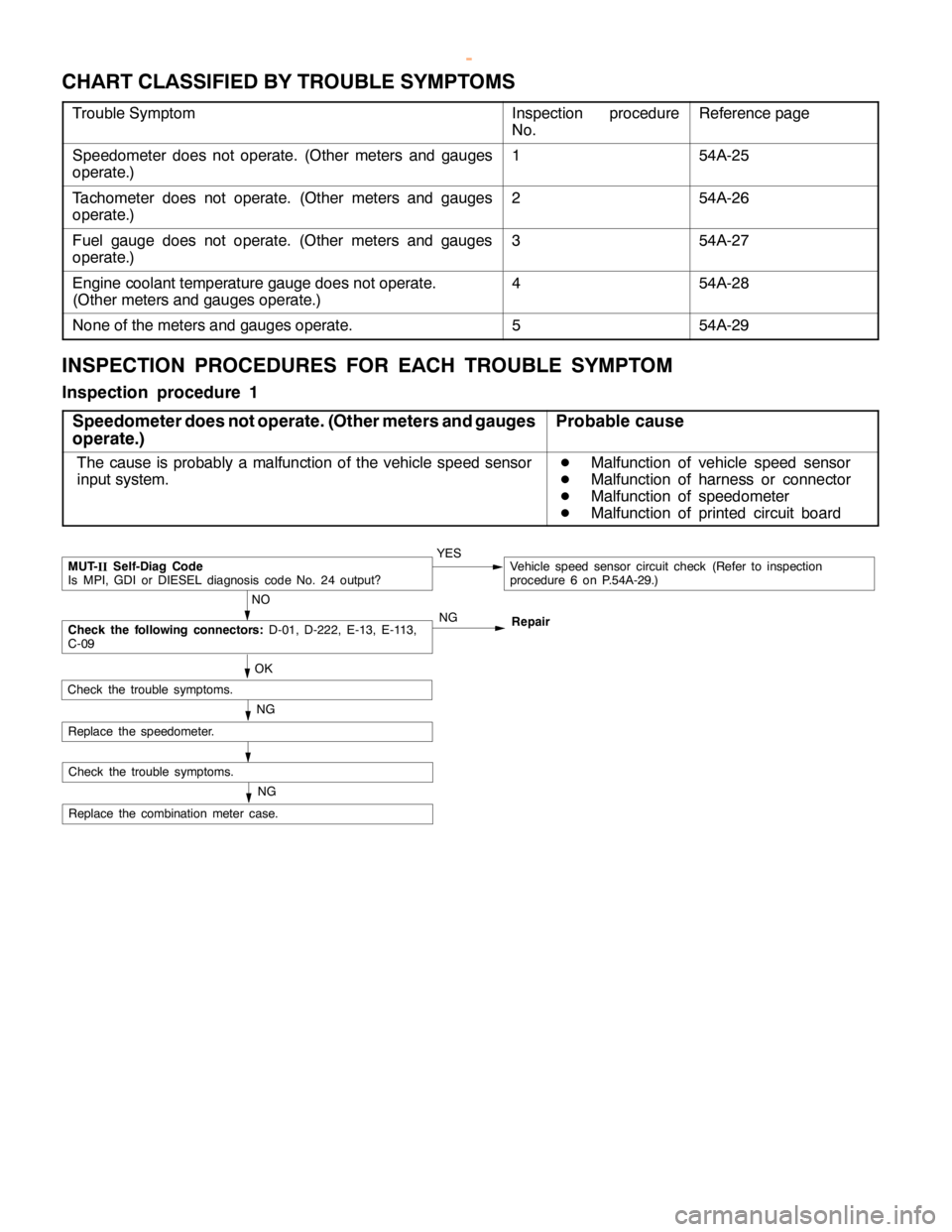
CHART CLASSIFIED BY TROUBLE SYMPTOMS
Trouble SymptomInspection procedure
No.Reference page
Speedometer does not operate. (Other meters and gauges
operate.)154A-25
Tachometer does not operate. (Other meters and gauges
operate.)254A-26
Fuel gauge does not operate. (Other meters and gauges
operate.)354A-27
Engine coolant temperature gauge does not operate.
(Other meters and gauges operate.)454A-28
None of the meters and gauges operate.554A-29
INSPECTION PROCEDURES FOR EACH TROUBLE SYMPTOM
Inspection procedure 1
Speedometer does not operate. (Other meters and gauges
operate.)
Probable cause
The cause is probably a malfunction of the vehicle speed sensor
input system.D
Malfunction of vehicle speed sensor
D
Malfunction of harness or connector
D
Malfunction of speedometer
D
Malfunction of printed circuit board
NO
MUT-
IISelf-Diag Code
Is MPI, GDI or DIESEL diagnosis code No. 24 output?YESVehicle speed sensor circuit check (Refer to inspection
procedure 6 on P.54A-29.)
OK
Replace the combination meter case.
NG
Check the trouble symptoms.
NGCheck the following connectors:D-01, D-222, E-13, E-113,
C-09Repair
NG
Check the trouble symptoms.
Replace the speedometer.
www.WorkshopManuals.co.uk
Purchased from www.WorkshopManuals.co.uk