2000 MITSUBISHI MONTERO check engine
[x] Cancel search: check enginePage 635 of 1839
DIESEL FUEL <4D5-stepIII>-Troubleshooting13E-25
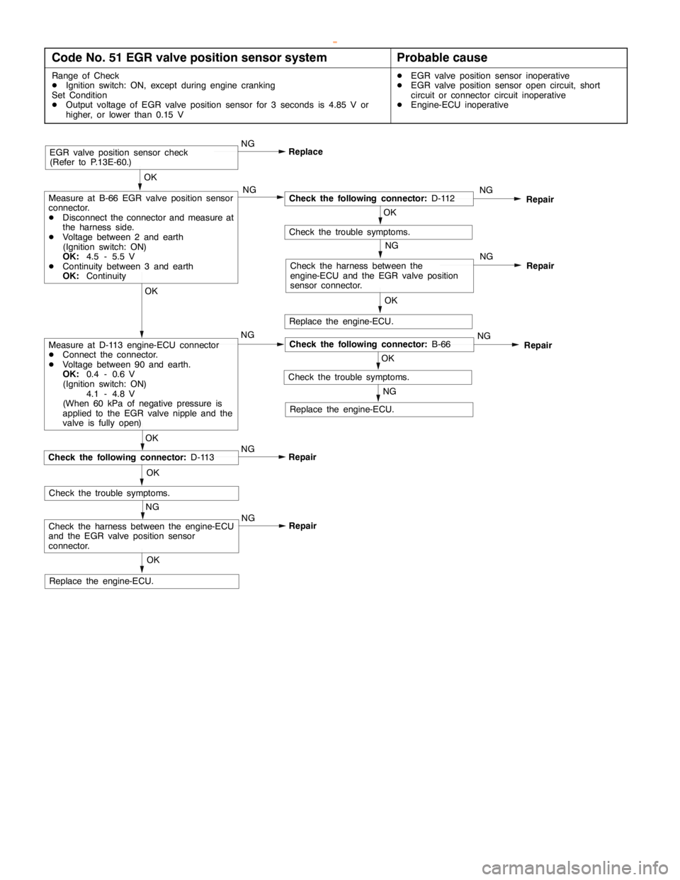
Code No. 51 EGR valve position sensor systemProbable cause
Range of Check
DIgnition switch: ON, except during engine cranking
Set Condition
DOutput voltage of EGR valve position sensor for 3 seconds is 4.85 V or
higher, or lower than 0.15 VDEGR valve position sensor inoperative
DEGR valve position sensor open circuit, short
circuit or connector circuit inoperative
DEngine-ECU inoperative
Repair NG
NG
OK
Check the harness between the engine-ECU
and the EGR valve position sensor
connector.
Replace the engine-ECU.
Repair NG
OK
NG
Repair
OK
OK
Check the harness between the
engine-ECU and the EGR valve position
sensor connector.
EGR valve position sensor check
(Refer to P.13E-60.)
OKReplace
Check the following connector:D-113
Check the trouble symptoms.NG
NG
Check the following connector:B-66NG
Repair
OK
Check the trouble symptoms.
NG
NGMeasure at D-113 engine-ECU connector
DConnect the connector.
DVoltage between 90 and earth.
OK:0.4 - 0.6 V
(Ignition switch: ON)
4.1 - 4.8 V
(When 60 kPa of negative pressure is
applied to the EGR valve nipple and the
valve is fully open)OK
Measure at B-66 EGR valve position sensor
connector.
DDisconnect the connector and measure at
the harness side.
DVoltage between 2 and earth
(Ignition switch: ON)
OK:4.5 - 5.5 V
DContinuity between 3 and earth
OK:Continuity
Replace the engine-ECU.
Replace the engine-ECU.
Check the following connector:D-112NG
Repair
OK
Check the trouble symptoms.
NG
www.WorkshopManuals.co.uk
Purchased from www.WorkshopManuals.co.uk
Page 636 of 1839
DIESEL FUEL <4D5-stepIII>-Troubleshooting13E-26
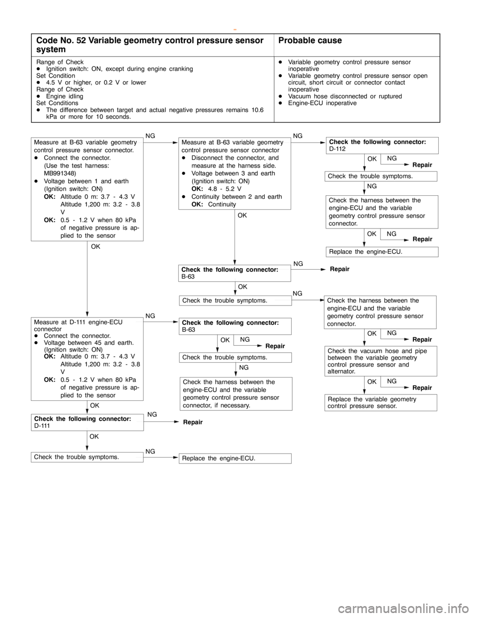
Code No. 52 Variable geometry control pressure sensor
systemProbable cause
Range of Check
DIgnition switch: ON, except during engine cranking
Set Condition
D4.5 V or higher, or 0.2 V or lower
Range of Check
DEngine idling
Set Conditions
DThe difference between target and actual negative pressures remains 10.6
kPa or more for 10 seconds.DVariable geometry control pressure sensor
inoperative
DVariable geometry control pressure sensor open
circuit, short circuit or connector contact
inoperative
DVacuum hose disconnected or ruptured
DEngine-ECU inoperative
NGReplace the engine-ECU.
Check the harness between the
engine-ECU and the variable
geometry control pressure sensor
connector, if necessary.
NG
Check the trouble symptoms.OK
NG
Repair
Replace the variable geometry
control pressure sensor.OK
NG
Repair
Check the vacuum hose and pipe
between the variable geometry
control pressure sensor and
alternator.OK
NG
Repair
NG
NG
Check the trouble symptoms.OK
Repair
Check the trouble symptoms.
OK
Replace the engine-ECU.OK
Repair NG NG
Check the harness between the
engine-ECU and the variable
geometry control pressure sensor
connector.
Check the trouble symptoms.OK
NG
Repair
Check the following connector:
D-111NG
Repair
OK
OKOK
Check the following connector:
B-63NG
NGNG
Check the following connector:
B-63
Measure at B-63 variable geometry
control pressure sensor connector.
DConnect the connector.
(Use the test harness:
MB991348)
DVoltage between 1 and earth
(Ignition switch: ON)
OK:Altitude 0 m: 3.7 - 4.3 V
Altitude 1,200 m: 3.2 - 3.8
V
OK:0.5 - 1.2 V when 80 kPa
of negative pressure is ap-
plied to the sensor
Measure at D-111 engine-ECU
connector
DConnect the connector.
DVoltage between 45 and earth.
(Ignition switch: ON)
OK:Altitude 0 m: 3.7 - 4.3 V
Altitude 1,200 m: 3.2 - 3.8
V
OK:0.5 - 1.2 V when 80 kPa
of negative pressure is ap-
plied to the sensor
Measure at B-63 variable geometry
control pressure sensor connector
DDisconnect the connector, and
measure at the harness side.
DVoltage between 3 and earth
(Ignition switch: ON)
OK:4.8 - 5.2 V
DContinuity between 2 and earth
OK:ContinuityCheck the following connector:
D-112
Check the harness between the
engine-ECU and the variable
geometry control pressure sensor
connector.
www.WorkshopManuals.co.uk
Purchased from www.WorkshopManuals.co.uk
Page 637 of 1839
DIESEL FUEL <4D5-stepIII>-Troubleshooting13E-27
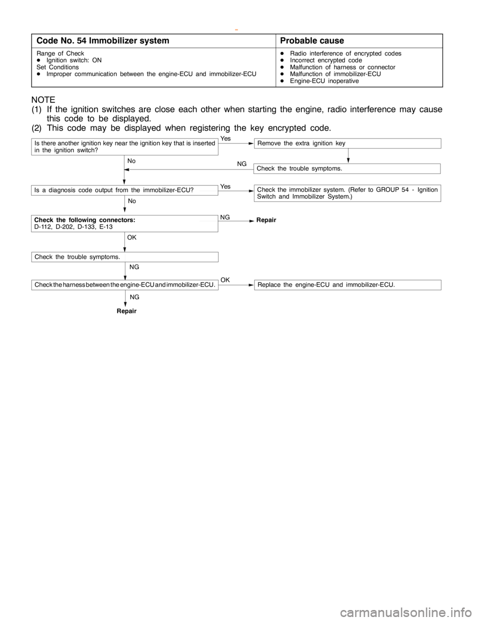
Code No. 54 Immobilizer systemProbable cause
Range of Check
DIgnition switch: ON
Set Conditions
DImproper communication between the engine-ECU and immobilizer-ECUDRadio interference of encrypted codes
DIncorrect encrypted code
DMalfunction of harness or connector
DMalfunction of immobilizer-ECU
DEngine-ECU inoperative
NOTE
(1) If the ignition switches are close each other when starting the engine, radio interference may cause
this code to be displayed.
(2) This code may be displayed when registering the key encrypted code.
Is there another ignition key near the ignition key that is inserted
in the ignition switch?Ye sRemove the extra ignition key
No
Check the following connectors:
D-112, D-202, D-133, E-13NG
Repair
No
Is a diagnosis code output from the immobilizer-ECU?Ye sCheck the immobilizer system. (Refer to GROUP 54 - Ignition
Switch and Immobilizer System.)
NG OK
Check the trouble symptoms.
Check the harness between the engine-ECU and immobilizer-ECU.OKReplace the engine-ECU and immobilizer-ECU.
Check the trouble symptoms. NG
RepairNG
www.WorkshopManuals.co.uk
Purchased from www.WorkshopManuals.co.uk
Page 639 of 1839
DIESEL FUEL <4D5-stepIII>-Troubleshooting13E-29
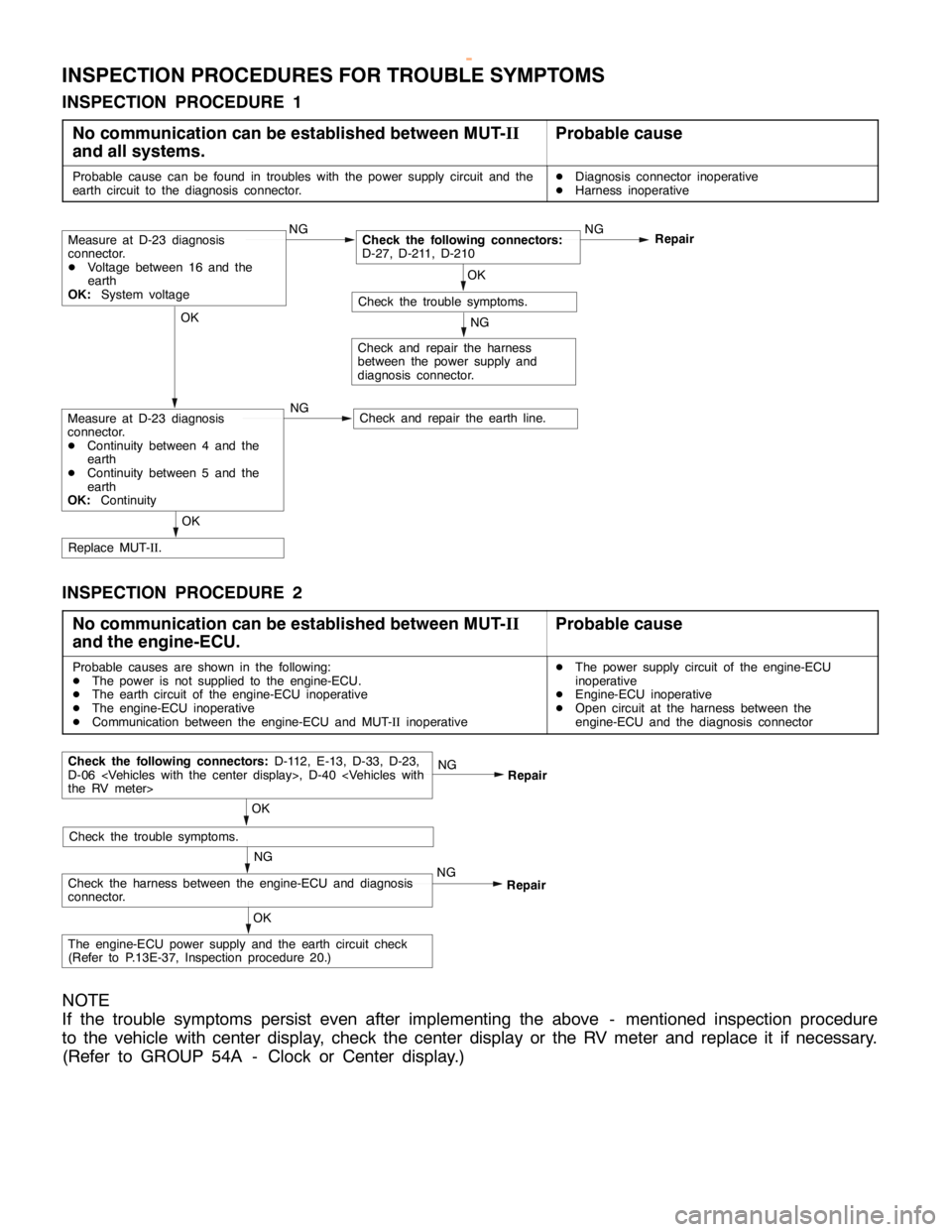
INSPECTION PROCEDURES FOR TROUBLE SYMPTOMS
INSPECTION PROCEDURE 1
No communication can be established between MUT-II
and all systems.
Probable cause
Probable cause can be found in troubles with the power supply circuit and the
earth circuit to the diagnosis connector.DDiagnosis connector inoperative
DHarness inoperative
OK
Check and repair the earth line.
OK
Replace MUT-II.
NG
Check and repair the harness
between the power supply and
diagnosis connector.
OK
Check the trouble symptoms.NG
Repair
NGCheck the following connectors:
D-27, D-211, D-210
NGMeasure at D-23 diagnosis
connector.
DVoltage between 16 and the
earth
OK:System voltage
Measure at D-23 diagnosis
connector.
DContinuity between 4 and the
earth
DContinuity between 5 and the
earth
OK:Continuity
INSPECTION PROCEDURE 2
No communication can be established between MUT-II
and the engine-ECU.
Probable cause
Probable causes are shown in the following:
DThe power is not supplied to the engine-ECU.
DThe earth circuit of the engine-ECU inoperative
DThe engine-ECU inoperative
DCommunication between the engine-ECU and MUT-IIinoperativeDThe power supply circuit of the engine-ECU
inoperative
DEngine-ECU inoperative
DOpen circuit at the harness between the
engine-ECU and the diagnosis connector
NG
Check the harness between the engine-ECU and diagnosis
connector.NGRepair
OK
Check the trouble symptoms.
Check the following connectors:D-112, E-13, D-33, D-23,
D-06
Repair
OK
The engine-ECU power supply and the earth circuit check
(Refer to P.13E-37, Inspection procedure 20.)
NOTE
If the trouble symptoms persist even after implementing the above - mentioned inspection procedure
to the vehicle with center display, check the center display or the RV meter and replace it if necessary.
(Refer to GROUP 54A - Clock or Center display.)
www.WorkshopManuals.co.uk
Purchased from www.WorkshopManuals.co.uk
Page 640 of 1839
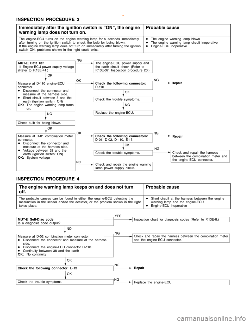
DIESEL FUEL <4D5-stepIII>-Troubleshooting13E-30
INSPECTION PROCEDURE 3
Immediately after the ignition switch is “ON”, the engine
warning lamp does not turn on.
Probable cause
The engine-ECU turns on the engine warning lamp for 5 seconds immediately
after turning on the ignition switch to check the bulb for being blown.
If the engine warning lamp does not turn on immediately after turning the ignition
switch ON, problems shown in the right could exist.DThe engine warning lamp blown
DThe engine warning lamp circuit inoperative
DEngine-ECU inoperative
NG
Replace the engine-ECU.
NG
Check and repair the harness
between the combination meter and
the engine-ECU connector.
NG
Check and repair the engine warning
lamp power supply circuit.
OK
Check the trouble symptoms.
OK
Measure at D-01 combination meter
connector.
DDisconnect the connector and
measure at the harness side.
DVoltage between 62 and the
earth (Ignition switch: ON)
OK:System voltageOKCheck the following connectors:
D-01, D-02, D-110, E-13NG
Repair
NG
Check bulb for being blown.
OK
Check the trouble symptoms.
OK
Measure at D-110 engine-ECU
connector.
DDisconnect the connector and
measure at the harness side.
DShort circuit between 8 and the
earth (Ignition switch: ON)
OK:The engine warning lamp turns
on.OKCheck the following connector:
D-110NG
Repair
MUT-IIData list
11 Engine-ECU power supply voltage
(Refer to P.13E-41.)NGThe engine-ECU power supply and
the earth circuit check (Refer to
P.13E-37, Inspection procedure 20.)
INSPECTION PROCEDURE 4
The engine warning lamp keeps on and does not turn
off.
Probable cause
The probable causes can be found in either the engine-ECU detecting the
malfunction in the sensor and/or the actuator, or the problem shown in the right
takes place.DShort circuit at the harness between the engine
warning lamp and the engine-ECU
DEngine-ECU inoperative
Check the following connector:E-13
NO
Measure at D-02 combination meter connector.
DDisconnect the connector and measure at the harness
side.
DDisconnect the engine-ECU connector D-110.
DContinuity between 38 and the earth
OK:No continuityNGCheck and repair the harness between the combination meter
and the engine-ECU connector.
OK
MUT-IISelf-Diag code
Is a diagnosis code output?YESInspection chart for diagnosis codes (Refer to P.13E-8.)
Check the trouble symptoms.OKReplace the engine-ECU. NGNG
Repair
www.WorkshopManuals.co.uk
Purchased from www.WorkshopManuals.co.uk
Page 641 of 1839
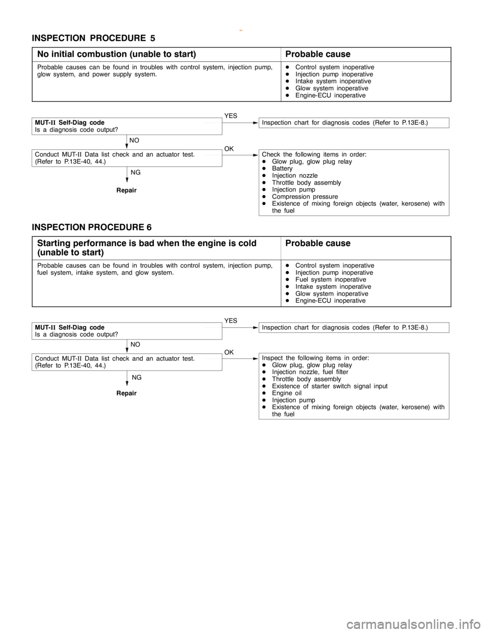
DIESEL FUEL <4D5-stepIII>-Troubleshooting13E-31
INSPECTION PROCEDURE 5
No initial combustion (unable to start)
Probable cause
Probable causes can be found in troubles with control system, injection pump,
glow system, and power supply system.DControl system inoperative
DInjection pump inoperative
DIntake system inoperative
DGlow system inoperative
DEngine-ECU inoperative
NG
Repair
MUT-IISelf-Diag code
Is a diagnosis code output?YESInspection chart for diagnosis codes (Refer to P.13E-8.)
NO
Conduct MUT-IIData list check and an actuator test.
(Refer to P.13E-40, 44.)OKCheck the following items in order:
DGlow plug, glow plug relay
DBattery
DInjection nozzle
DThrottle body assembly
DInjection pump
DCompression pressure
DExistence of mixing foreign objects (water, kerosene) with
the fuel
INSPECTION PROCEDURE 6
Starting performance is bad when the engine is cold
(unable to start)
Probable cause
Probable causes can be found in troubles with control system, injection pump,
fuel system, intake system, and glow system.DControl system inoperative
DInjection pump inoperative
DFuel system inoperative
DIntake system inoperative
DGlow system inoperative
DEngine-ECU inoperative
NG
Repair
MUT-IISelf-Diag code
Is a diagnosis code output?YESInspection chart for diagnosis codes (Refer to P.13E-8.)
NO
Conduct MUT-IIData list check and an actuator test.
(Refer to P.13E-40, 44.)OKInspect the following items in order:
DGlow plug, glow plug relay
DInjection nozzle, fuel filter
DThrottle body assembly
DExistence of starter switch signal input
DEngine oil
DInjection pump
DExistence of mixing foreign objects (water, kerosene) with
the fuel
www.WorkshopManuals.co.uk
Purchased from www.WorkshopManuals.co.uk
Page 642 of 1839
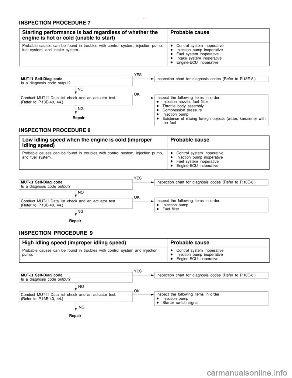
DIESEL FUEL <4D5-stepIII>-Troubleshooting13E-32
INSPECTION PROCEDURE 7
Starting performance is bad regardless of whether the
engine is hot or cold (unable to start)
Probable cause
Probable causes can be found in troubles with control system, injection pump,
fuel system, and intake system.DControl system inoperative
DInjection pump inoperative
DFuel system inoperative
DIntake system inoperative
DEngine-ECU inoperative
NG
Repair
MUT-IISelf-Diag code
Is a diagnosis code output?YESInspection chart for diagnosis codes (Refer to P.13E-8.)
NO
Conduct MUT-IIData list check and an actuator test.
(Refer to P.13E-40, 44.)OKInspect the following items in order:
DInjection nozzle, fuel filter
DThrottle body assembly
DCompression pressure
DInjection pump
DExistence of mixing foreign objects (water, kerosene) with
the fuel
INSPECTION PROCEDURE 8
Low idling speed when the engine is cold (improper
idling speed)
Probable cause
Probable causes can be found in troubles with control system, injection pump,
and fuel system.DControl system inoperative
DInjection pump inoperative
DFuel system inoperative
DEngine-ECU inoperative
NG
Repair
MUT-IISelf-Diag code
Is a diagnosis code output?YESInspection chart for diagnosis codes (Refer to P.13E-8.)
NO
Conduct MUT-IIData list check and an actuator test.
(Refer to P.13E-40, 44.)OKInspect the following items in order:
DInjection pump
DFuel filter
INSPECTION PROCEDURE 9
High idling speed (improper idling speed)
Probable cause
Probable causes can be found in troubles with control system and injection
pump.DControl system inoperative
DInjection pump inoperative
DEngine-ECU inoperative
NG
Repair
MUT-IISelf-Diag code
Is a diagnosis code output?YESInspection chart for diagnosis codes (Refer to P.13E-8.)
NO
Conduct MUT-IIData list check and an actuator test.
(Refer to P.13E-40, 44.)OKInspect the following items in order:
DInjection pump
DStarter switch signal
www.WorkshopManuals.co.uk
Purchased from www.WorkshopManuals.co.uk
Page 643 of 1839
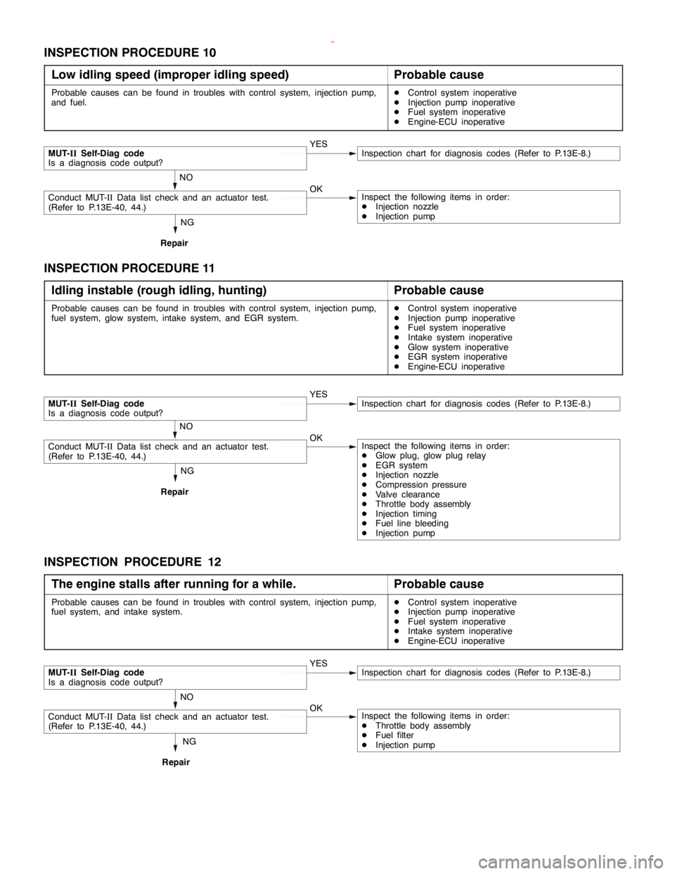
DIESEL FUEL <4D5-stepIII>-Troubleshooting13E-33
INSPECTION PROCEDURE 10
Low idling speed (improper idling speed)
Probable cause
Probable causes can be found in troubles with control system, injection pump,
and fuel.DControl system inoperative
DInjection pump inoperative
DFuel system inoperative
DEngine-ECU inoperative
NG
Repair
MUT-IISelf-Diag code
Is a diagnosis code output?YESInspection chart for diagnosis codes (Refer to P.13E-8.)
NO
Conduct MUT-IIData list check and an actuator test.
(Refer to P.13E-40, 44.)OKInspect the following items in order:
DInjection nozzle
DInjection pump
INSPECTION PROCEDURE 11
Idling instable (rough idling, hunting)
Probable cause
Probable causes can be found in troubles with control system, injection pump,
fuel system, glow system, intake system, and EGR system.DControl system inoperative
DInjection pump inoperative
DFuel system inoperative
DIntake system inoperative
DGlow system inoperative
DEGR system inoperative
DEngine-ECU inoperative
NG
Repair
MUT-IISelf-Diag code
Is a diagnosis code output?YESInspection chart for diagnosis codes (Refer to P.13E-8.)
NO
Conduct MUT-IIData list check and an actuator test.
(Refer to P.13E-40, 44.)OKInspect the following items in order:
DGlow plug, glow plug relay
DEGR system
DInjection nozzle
DCompression pressure
DValve clearance
DThrottle body assembly
DInjection timing
DFuel line bleeding
DInjection pump
INSPECTION PROCEDURE 12
The engine stalls after running for a while.
Probable cause
Probable causes can be found in troubles with control system, injection pump,
fuel system, and intake system.DControl system inoperative
DInjection pump inoperative
DFuel system inoperative
DIntake system inoperative
DEngine-ECU inoperative
NG
Repair
MUT-IISelf-Diag code
Is a diagnosis code output?YESInspection chart for diagnosis codes (Refer to P.13E-8.)
NO
Conduct MUT-IIData list check and an actuator test.
(Refer to P.13E-40, 44.)OKInspect the following items in order:
DThrottle body assembly
DFuel filter
DInjection pump
www.WorkshopManuals.co.uk
Purchased from www.WorkshopManuals.co.uk