2000 MITSUBISHI MONTERO check engine
[x] Cancel search: check enginePage 644 of 1839
DIESEL FUEL <4D5-stepIII>-Troubleshooting13E-34
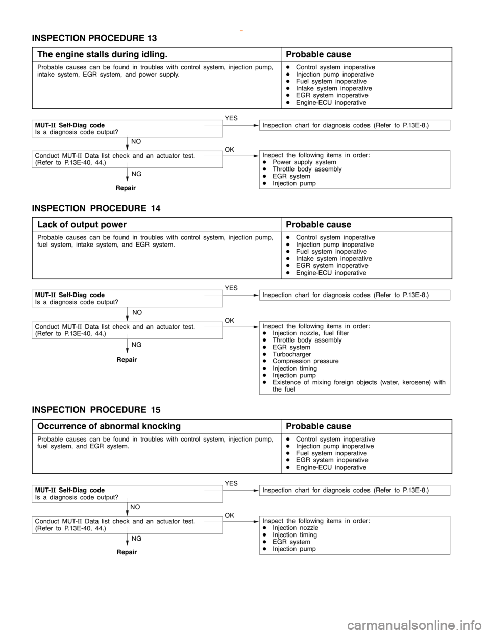
INSPECTION PROCEDURE 13
The engine stalls during idling.
Probable cause
Probable causes can be found in troubles with control system, injection pump,
intake system, EGR system, and power supply.DControl system inoperative
DInjection pump inoperative
DFuel system inoperative
DIntake system inoperative
DEGR system inoperative
DEngine-ECU inoperative
NG
Repair
MUT-IISelf-Diag code
Is a diagnosis code output?YESInspection chart for diagnosis codes (Refer to P.13E-8.)
NO
Conduct MUT-IIData list check and an actuator test.
(Refer to P.13E-40, 44.)OKInspect the following items in order:
DPower supply system
DThrottle body assembly
DEGR system
DInjection pump
INSPECTION PROCEDURE 14
Lack of output power
Probable cause
Probable causes can be found in troubles with control system, injection pump,
fuel system, intake system, and EGR system.DControl system inoperative
DInjection pump inoperative
DFuel system inoperative
DIntake system inoperative
DEGR system inoperative
DEngine-ECU inoperative
NG
Repair
MUT-IISelf-Diag code
Is a diagnosis code output?YESInspection chart for diagnosis codes (Refer to P.13E-8.)
NO
Conduct MUT-IIData list check and an actuator test.
(Refer to P.13E-40, 44.)OKInspect the following items in order:
DInjection nozzle, fuel filter
DThrottle body assembly
DEGR system
DTurbocharger
DCompression pressure
DInjection timing
DInjection pump
DExistence of mixing foreign objects (water, kerosene) with
the fuel
INSPECTION PROCEDURE 15
Occurrence of abnormal knocking
Probable cause
Probable causes can be found in troubles with control system, injection pump,
fuel system, and EGR system.DControl system inoperative
DInjection pump inoperative
DFuel system inoperative
DEGR system inoperative
DEngine-ECU inoperative
NG
Repair
MUT-IISelf-Diag code
Is a diagnosis code output?YESInspection chart for diagnosis codes (Refer to P.13E-8.)
NO
Conduct MUT-IIData list check and an actuator test.
(Refer to P.13E-40, 44.)OKInspect the following items in order:
DInjection nozzle
DInjection timing
DEGR system
DInjection pump
www.WorkshopManuals.co.uk
Purchased from www.WorkshopManuals.co.uk
Page 645 of 1839
DIESEL FUEL <4D5-stepIII>-Troubleshooting13E-35
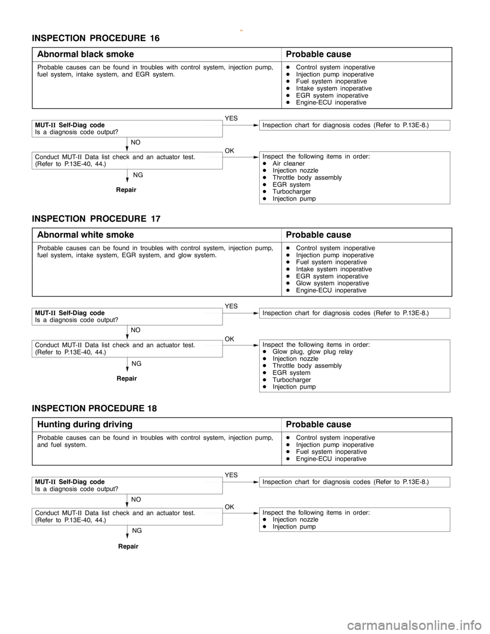
INSPECTION PROCEDURE 16
Abnormal black smoke
Probable cause
Probable causes can be found in troubles with control system, injection pump,
fuel system, intake system, and EGR system.DControl system inoperative
DInjection pump inoperative
DFuel system inoperative
DIntake system inoperative
DEGR system inoperative
DEngine-ECU inoperative
NG
Repair
MUT-IISelf-Diag code
Is a diagnosis code output?YESInspection chart for diagnosis codes (Refer to P.13E-8.)
NO
Conduct MUT-IIData list check and an actuator test.
(Refer to P.13E-40, 44.)OKInspect the following items in order:
DAir cleaner
DInjection nozzle
DThrottle body assembly
DEGR system
DTurbocharger
DInjection pump
INSPECTION PROCEDURE 17
Abnormal white smoke
Probable cause
Probable causes can be found in troubles with control system, injection pump,
fuel system, intake system, EGR system, and glow system.DControl system inoperative
DInjection pump inoperative
DFuel system inoperative
DIntake system inoperative
DEGR system inoperative
DGlow system inoperative
DEngine-ECU inoperative
NG
Repair
MUT-IISelf-Diag code
Is a diagnosis code output?YESInspection chart for diagnosis codes (Refer to P.13E-8.)
NO
Conduct MUT-IIData list check and an actuator test.
(Refer to P.13E-40, 44.)OKInspect the following items in order:
DGlow plug, glow plug relay
DInjection nozzle
DThrottle body assembly
DEGR system
DTurbocharger
DInjection pump
INSPECTION PROCEDURE 18
Hunting during driving
Probable cause
Probable causes can be found in troubles with control system, injection pump,
and fuel system.DControl system inoperative
DInjection pump inoperative
DFuel system inoperative
DEngine-ECU inoperative
NG
Repair
MUT-IISelf-Diag code
Is a diagnosis code output?YESInspection chart for diagnosis codes (Refer to P.13E-8.)
NO
Conduct MUT-IIData list check and an actuator test.
(Refer to P.13E-40, 44.)OKInspect the following items in order:
DInjection nozzle
DInjection pump
www.WorkshopManuals.co.uk
Purchased from www.WorkshopManuals.co.uk
Page 646 of 1839
DIESEL FUEL <4D5-stepIII>-Troubleshooting13E-36
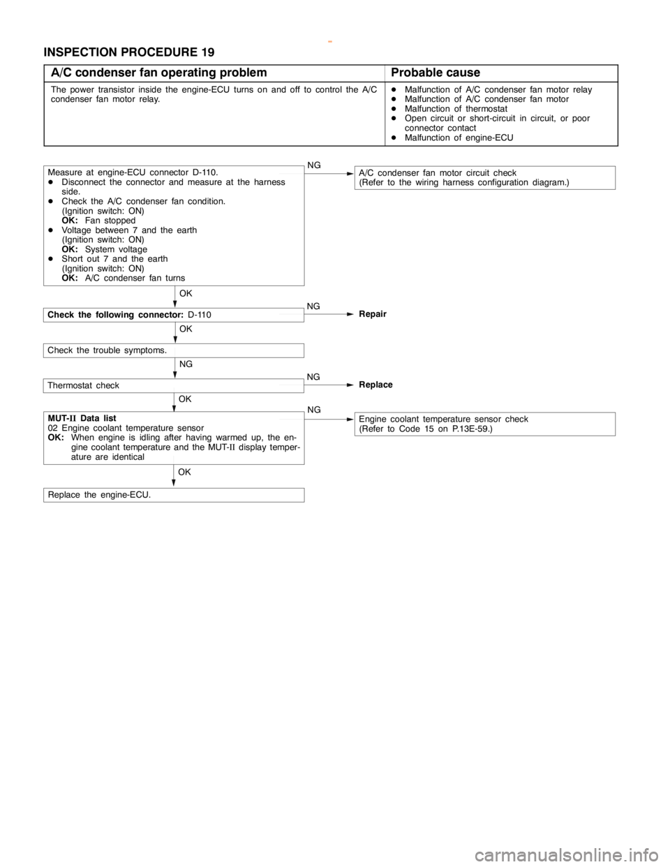
INSPECTION PROCEDURE 19
A/C condenser fan operating problem
Probable cause
The power transistor inside the engine-ECU turns on and off to control the A/C
condenser fan motor relay.DMalfunction of A/C condenser fan motor relay
DMalfunction of A/C condenser fan motor
DMalfunction of thermostat
DOpen circuit or short-circuit in circuit, or poor
connector contact
DMalfunction of engine-ECU
Check the following connector:D-110
OK
Measure at engine-ECU connector D-110.
DDisconnect the connector and measure at the harness
side.
DCheck the A/C condenser fan condition.
(Ignition switch: ON)
OK:Fan stopped
DVoltage between 7 and the earth
(Ignition switch: ON)
OK:System voltage
DShort out 7 and the earth
(Ignition switch: ON)
OK:A/C condenser fan turnsNGA/C condenser fan motor circuit check
(Refer to the wiring harness configuration diagram.)
OK
MUT-IIData list
02 Engine coolant temperature sensor
OK:When engine is idling after having warmed up, the en-
gine coolant temperature and the MUT-IIdisplay temper-
ature are identicalNGEngine coolant temperature sensor check
(Refer to Code 15 on P.13E-59.)
Check the trouble symptoms.OK
Replace the engine-ECU.NG
Repair
Thermostat checkNG
NGReplace
OK
www.WorkshopManuals.co.uk
Purchased from www.WorkshopManuals.co.uk
Page 647 of 1839
DIESEL FUEL <4D5-stepIII>-Troubleshooting13E-37
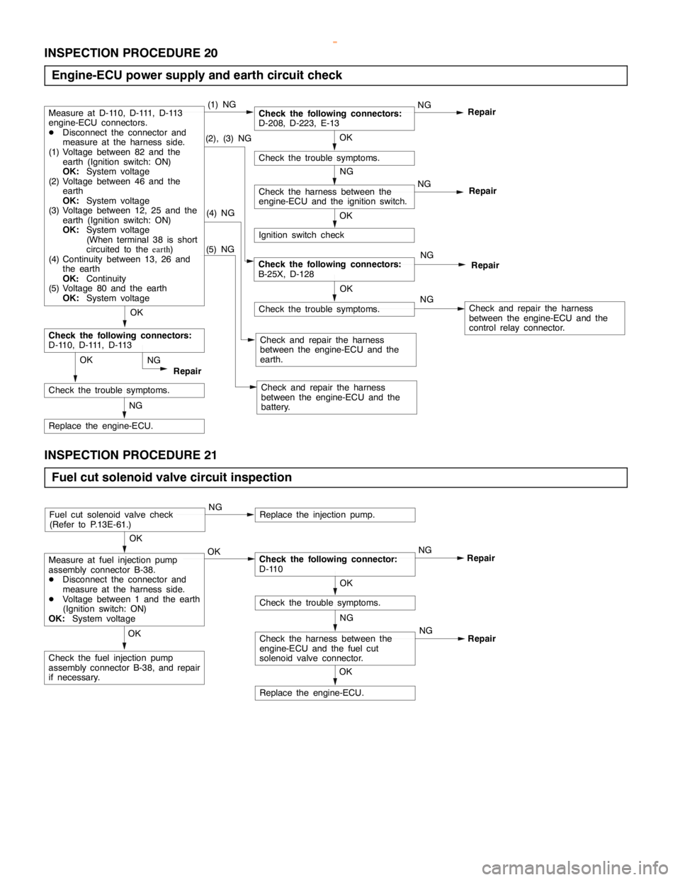
INSPECTION PROCEDURE 20
Engine-ECU power supply and earth circuit check
(5) NG
Check the trouble symptoms.
NG
Repair
(2), (3) NGOK
Check the trouble symptoms.
OK
NG
Check the harness between the
engine-ECU and the ignition switch.
Ignition switch check
(4) NG
Check and repair the harness
between the engine-ECU and the
earth.
OK
Check the following connectors:
D-110, D-111, D-113
NG
Replace the engine-ECU.
OK
Check the trouble symptoms.Repair NG
NG
RepairCheck the following connectors:
B-25X, D-128
NG
Check and repair the harness
between the engine-ECU and the
control relay connector.
Check and repair the harness
between the engine-ECU and the
battery.
Check the following connectors:
D-208, D-223, E-13NG
RepairMeasure at D-110, D-111, D-113
engine-ECU connectors.
DDisconnect the connector and
measure at the harness side.
(1) Voltage between 82 and the
earth (Ignition switch: ON)
OK:System voltage
(2) Voltage between 46 and the
earth
OK:System voltage
(3) Voltage between 12, 25 and the
earth (Ignition switch: ON)
OK:System voltage
(When terminal 38 is short
circuited to theearth)
(4) Continuity between 13, 26 and
the earth
OK:Continuity
(5) Voltage 80 and the earth
OK:System voltage(1) NG
OK
INSPECTION PROCEDURE 21
Fuel cut solenoid valve circuit inspection
NG
Check the harness between the
engine-ECU and the fuel cut
solenoid valve connector.
OK
Replace the engine-ECU.
OK
Check the fuel injection pump
assembly connector B-38, and repair
if necessary.
OK
Check the trouble symptoms.
OK
Measure at fuel injection pump
assembly connector B-38.
DDisconnect the connector and
measure at the harness side.
DVoltage between 1 and the earth
(Ignition switch: ON)
OK:System voltageOKCheck the following connector:
D-110NG
Repair
Fuel cut solenoid valve check
(Refer to P.13E-61.)NGReplace the injection pump.
NG
Repair
www.WorkshopManuals.co.uk
Purchased from www.WorkshopManuals.co.uk
Page 648 of 1839
DIESEL FUEL <4D5-stepIII>-Troubleshooting13E-38
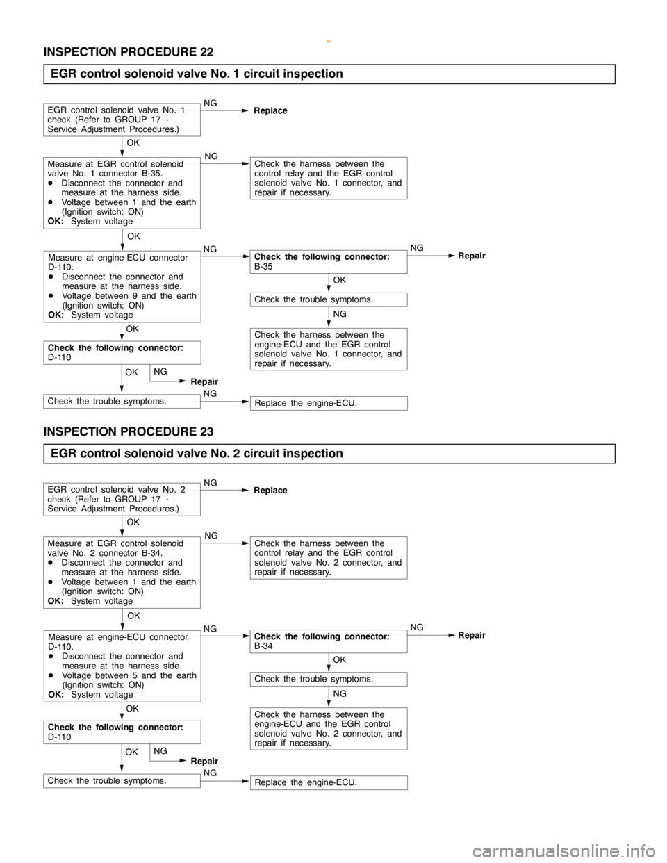
INSPECTION PROCEDURE 22
EGR control solenoid valve No. 1 circuit inspection
NG
Check the harness between the
engine-ECU and the EGR control
solenoid valve No. 1 connector, and
repair if necessary.
OK
Check the trouble symptoms.
OK
Measure at EGR control solenoid
valve No. 1 connector B-35.
DDisconnect the connector and
measure at the harness side.
DVoltage between 1 and the earth
(Ignition switch: ON)
OK:System voltage
NG
Check the following connector:
B-35NG
Repair NG
Check the harness between the
control relay and the EGR control
solenoid valve No. 1 connector, and
repair if necessary.
EGR control solenoid valve No. 1
check (Refer to GROUP 17 -
Service Adjustment Procedures.)NG
Replace
OK
Measure at engine-ECU connector
D-110.
DDisconnect the connector and
measure at the harness side.
DVoltage between 9 and the earth
(Ignition switch: ON)
OK:System voltage
NG
Replace the engine-ECU. NGCheck the trouble symptoms.OK
Repair
Check the following connector:
D-110OK
INSPECTION PROCEDURE 23
EGR control solenoid valve No. 2 circuit inspection
NG
Check the harness between the
engine-ECU and the EGR control
solenoid valve No. 2 connector, and
repair if necessary.
OK
Check the trouble symptoms.
OK
Measure at EGR control solenoid
valve No. 2 connector B-34.
DDisconnect the connector and
measure at the harness side.
DVoltage between 1 and the earth
(Ignition switch: ON)
OK:System voltage
NG
Check the following connector:
B-34NG
Repair NG
Check the harness between the
control relay and the EGR control
solenoid valve No. 2 connector, and
repair if necessary.
EGR control solenoid valve No. 2
check (Refer to GROUP 17 -
Service Adjustment Procedures.)NG
Replace
OK
Measure at engine-ECU connector
D-110.
DDisconnect the connector and
measure at the harness side.
DVoltage between 5 and the earth
(Ignition switch: ON)
OK:System voltage
NG
Replace the engine-ECU. NGCheck the trouble symptoms.OK
Repair
Check the following connector:
D-110OK
www.WorkshopManuals.co.uk
Purchased from www.WorkshopManuals.co.uk
Page 649 of 1839
DIESEL FUEL <4D5-stepIII>-Troubleshooting13E-39
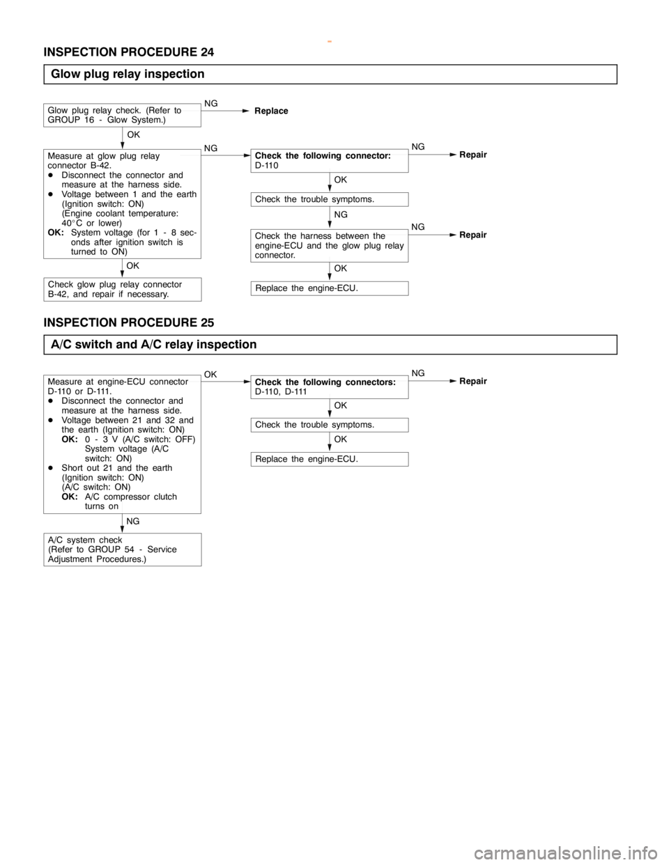
INSPECTION PROCEDURE 24
Glow plug relay inspection
NG
Replace the engine-ECU.
OK
Check the trouble symptoms.
OK
Measure at glow plug relay
connector B-42.
DDisconnect the connector and
measure at the harness side.
DVoltage between 1 and the earth
(Ignition switch: ON)
(Engine coolant temperature:
40_C or lower)
OK:System voltage (for 1 - 8 sec-
onds after ignition switch is
turned to ON)NGCheck the following connector:
D-110NG
Repair
Glow plug relay check. (Refer to
GROUP 16 - Glow System.)NG
Replace
Check glow plug relay connector
B-42, and repair if necessary.OK
OK
Check the harness between the
engine-ECU and the glow plug relay
connector.NG
Repair
INSPECTION PROCEDURE 25
A/C switch and A/C relay inspection
Replace the engine-ECU.
OK
Check the trouble symptoms.
Measure at engine-ECU connector
D-110 or D-111.
DDisconnect the connector and
measure at the harness side.
DVoltage between 21 and 32 and
the earth (Ignition switch: ON)
OK:0 - 3 V (A/C switch: OFF)
System voltage (A/C
switch: ON)
DShort out 21 and the earth
(Ignition switch: ON)
(A/C switch: ON)
OK:A/C compressor clutch
turns onOKCheck the following connectors:
D-110, D-111NG
Repair
A/C system check
(Refer to GROUP 54 - Service
Adjustment Procedures.)NGOK
www.WorkshopManuals.co.uk
Purchased from www.WorkshopManuals.co.uk
Page 650 of 1839

DIESEL FUEL <4D5-stepIII>-Troubleshooting13E-40
DATA LIST REFERENCE TABLE
Item
No.Check itemInspection conditionsValue to be
determined
as normalCode No.
or inspec-
tion proce-
dure No.Reference
page
01Boost air
temperatureIgnition switch: ON or
the engine runningWhen the intake air
temperature is - 20_C-20_CCode No.
1613E-12
p
sensor
gg
When the intake air
temperature is 0_C0_C
When the intake air
temperature is 20_C20_C
When the intake air
temperature is 40_C40_C
When the intake air
temperature is 80_C80_C
02Engine
coolant
temperatureIgnition switch: ON or
the engine runningWhen the engine
coolant temperature is
-20_C-20_CCode No.
1513E-12
p
sensorWhen the engine
coolant temperature is
0_C0_C
When the engine
coolant temperature is
20_C20_C
When the engine
coolant temperature is
40_C40_C
When the engine
coolant temperature is
80_C80_C
03BarometricIgnition switch: ONAltitude 0 m101 kPaCode No.
13
13E-11
pressure
sensor
g
Altitude 600 m95 kPa13
sensorAltitude 1,200 m88 kPa
Altitude 1,800 m81 kPa
04BoostDEngine coolant
tt
Altitude 0 m101 kPaCode No.
12
13E-10
pressure
sensor
g
temperature:
80-95_CAltitude 600 m95 kPa12
sensor80-95_C
DLamps, electricalAltitude 1,200 m88 kPaLamps,electrical
cooling fan, and
accessories:OFFAltitude 1,800 m81 kPaaccessories:OFF
DTransmission:Idling81 - 109 kPaDTransmission:
Neutral
DIgnition switch: ONWhen sudden racing is
doneIncreased
05Fuel
temperatureIgnition switch: ON or
the engine runningWhen the fuel
temperature is - 20_C-20_CCode No.
1413E-11
p
sensor
gg
When the fuel
temperature is 0_C0_C
When the fuel
temperature is 20_C20_C
When the fuel
temperature is 40_C40_C
When the fuel
temperature is 80_C80_C
www.WorkshopManuals.co.uk
Purchased from www.WorkshopManuals.co.uk
Page 651 of 1839

DIESEL FUEL <4D5-stepIII>-Troubleshooting13E-41
Item
No.Reference
page Code No.
or inspec-
tion proce-
dure No. Value to be
determined
as normal Inspection conditions Check item
06Vehicle
speed
sensorWhen drivingCompare the engine
speed displayed in the
speed meter with that
in MUT-IIMatchedCode No.
1713E-13
07Pump
speedEngine: CrankingCompare the engine
speed displayed in theMatchedCode No.
1813E-14
speed
sensorEngine: Idling
speeddisplayedinthe
tachometer with that in
MUT-II
18
08Crank angle
sensorEngine: CrankingCompare the engine
speed displayed in theMatchedCode No.
2113E-15
sensor
Engine: Idling
speeddisplayedinthe
tachometer with that in
MUT-II
21
09Accelerator
pedal posi-
tionsensor
Ignition switch: ONAccelerator pedal:
Idling position1,015 - 1,055
mVCode No.
1113E-9
tion sensor
(main)Accelerator pedal:
Fully opened position4,035 - 4,500
mV or higher
10Accelerator
pedal posi-
ti
Ignition switch: ONAccelerator pedal:
Idling position0%Code No.
1113E-9
pp
tion sensor
(main)Accelerator pedal:
Fully opened position99 - 100 %
11System volt-
ageIgnition switch: ONSystem volt-
ageProcedure
No. 2013E-37
13Timing
tl
Engine: After warming
thi
Idling70 - 90 %Code No.
25N
13E-17g
control
valve*1
gg
up the engineWhen engine is
suddenly racedChanges25 or No.
4313E-21
14EGR com-
dl
Engine: After warming
thi
Idling0 - 100 %*2–-
mand value
gg
up the engineWhen engine is
suddenly racedMomentarily
decreases
17Control
sleeve posi-Engine: After warming
up the engineIdling2.1 - 2.5 VCode No.
2613E-18
sleeveposi
tion (target
value)
uptheengine
2,500 r/min (no load)1.8 - 2.2 V
26
18Actual injec-
titi i
Engine: After warming
thi
Idling0.7 - 1.2 V––j
tion timing
gg
up the engineWhen engine is
suddenly racedIncreases
19Injection
ti i
Engine: After warming
thi
Idling0.7 - 1.2 V––j
timing com-
mand value
gg
up the engineWhen engine is
suddenly racedIncreases
21GE actuatorEngine: After warming
uptheengine
Idling0%Code No.
26orNo
13E-18
13E 23upthe engine2,500 r/min18 - 38 %26orNo.
4813E-23
23Control
sleeve posi-Engine: After warming
up the engineIdling2.1 - 2.5 VCode No.
2613E-18
sleeveposi
tion (actual
l)
uptheengine
2,500 r/min (no load)1.8 - 2.2 V
26
(
value)2,500r/min(noload)1.82.2V
24Accelerator
pedal posi-
ti
Ignition switch: ONAccelerator pedal:
Idling position1,015 - 1,055
mVCode No.
2713E-19
pp
tion sensor
(sub)Accelerator pedal:
Fully opened position4,035 - 4,500
mV or higher
www.WorkshopManuals.co.uk
Purchased from www.WorkshopManuals.co.uk