2000 MITSUBISHI MONTERO check engine
[x] Cancel search: check enginePage 561 of 1839
DIESEL FUEL <4M4> -Troubleshooting13C-6
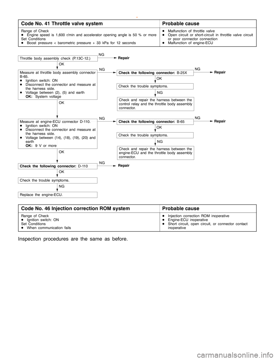
Code No. 41 Throttle valve systemProbable cause
Range of Check
DEngine speed is 1,600 r/min and accelerator opening angle is 50 % or more
Set Conditions
DBoost pressure < barometric pressure + 33 kPa for 12 secondsDMalfunction of throttle valve
DOpen circuit or short-circuit in throttle valve circuit
or poor connector connection
DMalfunction of engine-ECU
NG
Replace the engine-ECU.
OK
Check the trouble symptoms.
OK
NG
Check the following connector:D-110
OK
Check the trouble symptoms.
NG
Check and repair the harness between the
engine-ECU and the throttle body assembly
connector.
Repair NG
OK
Check the following connector:B-65 NG
OK
Check the trouble symptoms.
NG
Check and repair the harness between the
control relay and the throttle body assembly
connector.
Repair NG
OK
Check the following connector:B-25X NGMeasure at throttle body assembly connector
B-65.
DIgnition switch: ON
DDisconnect the connector and measure at
the harness side.
DVoltage between (2), (5) and earth
OK:System voltage
RepairThrottle body assembly check (P.13C-12.)NG
Measure at engine-ECU connector D-110.
DIgnition switch: ON
DDisconnect the connector and measure at
the harness side.
DVoltage between (14), (18), (19), (20) and
earth
OK:9 V or more
Repair
Code No. 46 Injection correction ROM systemProbable cause
Range of Check
DIgnition switch: ON
Set Conditions
DWhen communication failsDInjection correction ROM inoperative
DEngine-ECU inoperative
DShort circuit, open circuit, or connector contact
inoperative
Inspection procedures are the same as before.
www.WorkshopManuals.co.uk
Purchased from www.WorkshopManuals.co.uk
Page 562 of 1839
DIESEL FUEL <4M4> -Troubleshooting13C-7
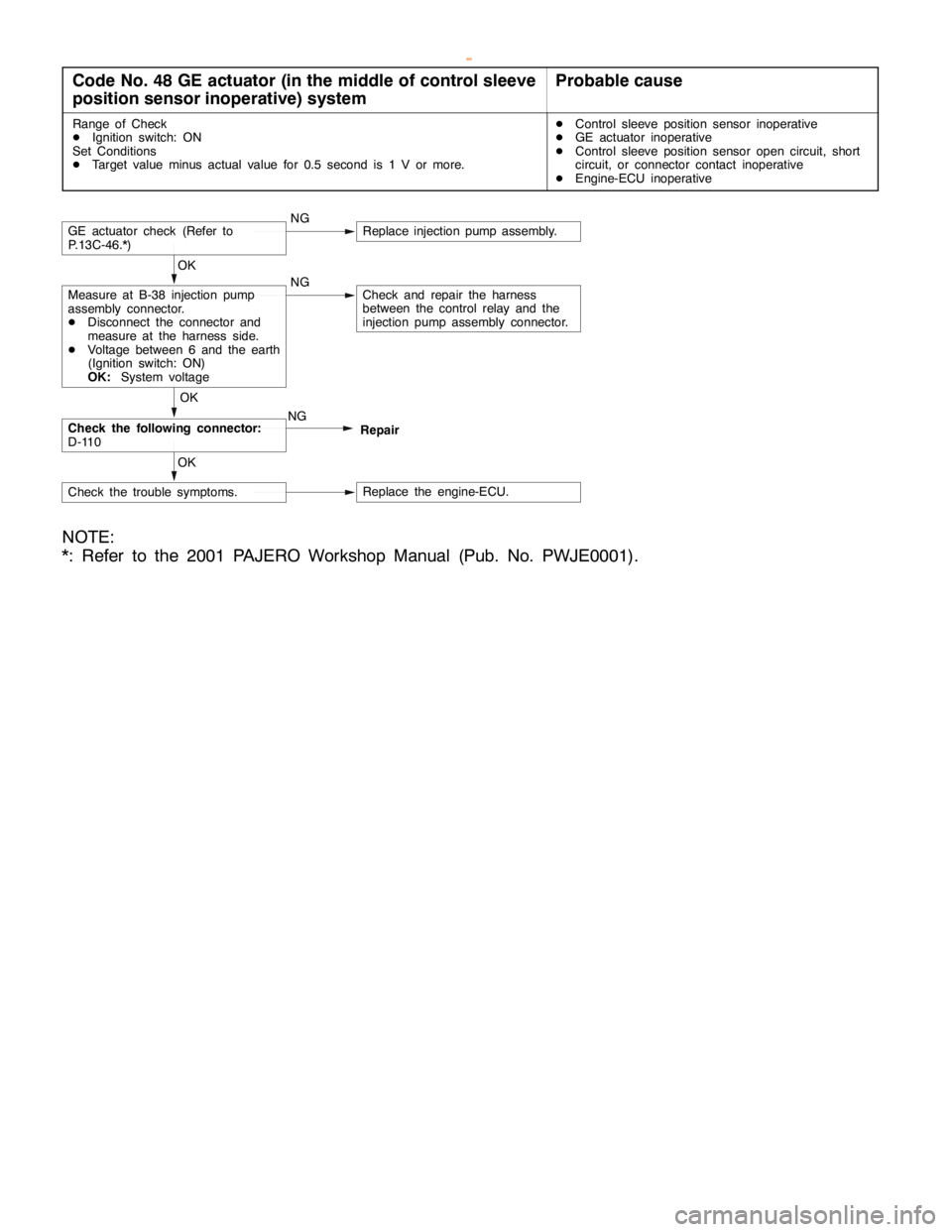
Code No. 48 GE actuator (in the middle of control sleeve
position sensor inoperative) systemProbable cause
Range of Check
DIgnition switch: ON
Set Conditions
DTarget value minus actual value for 0.5 second is 1 V or more.DControl sleeve position sensor inoperative
DGE actuator inoperative
DControl sleeve position sensor open circuit, short
circuit, or connector contact inoperative
DEngine-ECU inoperative
NGGE actuator check (Refer to
P.13C-46.*)Replace injection pump assembly.
NGMeasure at B-38 injection pump
assembly connector.
DDisconnect the connector and
measure at the harness side.
DVoltage between 6 and the earth
(Ignition switch: ON)
OK:System voltageCheck and repair the harness
between the control relay and the
injection pump assembly connector. OK
Check the following connector:
D-110NG OK
Repair
Check the trouble symptoms.Replace the engine-ECU. OK
NOTE:
*: Refer to the 2001 PAJERO Workshop Manual (Pub. No. PWJE0001).
www.WorkshopManuals.co.uk
Purchased from www.WorkshopManuals.co.uk
Page 563 of 1839
DIESEL FUEL <4M4> -Troubleshooting13C-8
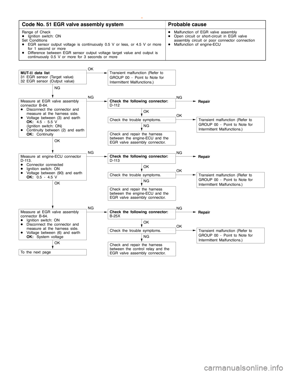
Code No. 51 EGR valve assembly systemProbable cause
Range of Check
DIgnition switch: ON
Set Conditions
DEGR sensor output voltage is continuously 0.5 V or less, or 4.5 V or more
for 1 second or more
DDifference between EGR sensor output voltage target value and output is
continuously 0.5 V or more for 3 seconds or moreDMalfunction of EGR valve assembly
DOpen circuit or short-circuit in EGR valve
assembly circuit or poor connector connection
DMalfunction of engine-ECU
Check and repair the harness
between the engine-ECU and the
EGR valve assembly connector.
NG
OKCheck the trouble symptoms.
OK
Transient malfunction (Refer to
GROUP 00 - Point to Note for
Intermittent Malfunctions.)
NGMeasure at engine-ECU connector
D-113.
DConnector connected
DIgnition switch: ON
DVoltage between (90) and earth
OK:0.5 - 4.5 VCheck the following connector:
D-113NG
Repair OK
Check and repair the harness
between the engine-ECU and the
EGR valve assembly connector.
NG
OKCheck the trouble symptoms.
OK
Transient malfunction (Refer to
GROUP 00 - Point to Note for
Intermittent Malfunctions.)
OKMUT-IIdata list
31 EGR sensor (Target value)
32 EGR sensor (Output value)Transient malfunction (Refer to
GROUP 00 - Point to Note for
Intermittent Malfunctions.)
NGMeasure at EGR valve assembly
connector B-64.
DDisconnect the connector and
measure at the harness side.
DVoltage between (3) and earth
OK:4.5 - 5.5 V
(Ignition switch: ON)
DContinuity between (2) and earth
OK:ContinuityCheck the following connector:
D-112NG
Repair NG
To the next pageOK
Check and repair the harness
between the control relay and the
EGR valve assembly connector.
NG
OKCheck the trouble symptoms.
OK
Transient malfunction (Refer to
GROUP 00 - Point to Note for
Intermittent Malfunctions.)
NGMeasure at EGR valve assembly
connector B-64.
DIgnition switch: ON
DDisconnect the connector and
measure at the harness side.
DVoltage between (6) and earth
OK:System voltageCheck the following connector:
B-25XNG
Repair OK
www.WorkshopManuals.co.uk
Purchased from www.WorkshopManuals.co.uk
Page 564 of 1839
DIESEL FUEL <4M4> -Troubleshooting13C-9
Replace the engine-ECU.
Replace the EGR valve assembly.NG
Check the following connector:
D-113NG OK
Check and repair the harness
between the engine-ECU and the
EGR valve assembly connector.
NG
OKCheck the trouble symptoms.
OK
Transient malfunction (Refer to
GROUP 00 - Point to Note for
Intermittent Malfunctions.)
From the previous page
NGMeasure at engine-ECU connector
D-113.
DIgnition switch: ON
DDisconnect the connector and
measure at the harness side.
DVoltage between (17) and earth
OK:System voltageCheck the following connector:
B-64NG
Repair OK
NG
OKCheck the trouble symptoms.Transient malfunction (Refer to
GROUP 00 - Point to Note for
Intermittent Malfunctions.) OKRepair
Check the trouble symptoms.OK
End
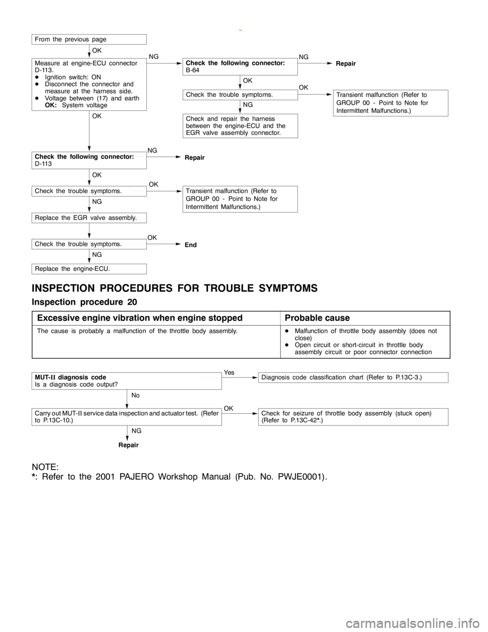
INSPECTION PROCEDURES FOR TROUBLE SYMPTOMS
Inspection procedure 20
Excessive engine vibration when engine stopped
Probable cause
The cause is probably a malfunction of the throttle body assembly.DMalfunction of throttle body assembly (does not
close)
DOpen circuit or short-circuit in throttle body
assembly circuit or poor connector connection
MUT-IIdiagnosis code
Is a diagnosis code output?Ye sDiagnosis code classification chart (Refer to P.13C-3.)
No
Carry out MUT-IIservice data inspection and actuator test. (Refer
to P.13C-10.)OKCheck for seizure of throttle body assembly (stuck open)
(Refer to P.13C-42*.)
RepairNG
NOTE:
*: Refer to the 2001 PAJERO Workshop Manual (Pub. No. PWJE0001).
www.WorkshopManuals.co.uk
Purchased from www.WorkshopManuals.co.uk
Page 565 of 1839

DIESEL FUEL <4M4> -Troubleshooting13C-10
DATA LIST REFERENCE TABLE
Item No.Check itemInspection
conditionsValue to be
determined normalCode No. or
inspection
procedure No.Reference page
31EGR sensor
(Target value)Engine: RacingChanges between 0.5
V and 4.5 VCode No. 5113C-8
32EGR sensor
(Output value)Engine: RacingApproaches EGR
sensor (target value).Code No. 5113C-8
36Throttle body
assembly
(Target value)Engine: Idling30 degCode No. 4113C-6
ACTUATOR TEST TABLE
Item No.Check itemDrive contentsInspection
conditionsValue to be
determined as
normalCode No. or
inspection
procedure No.Reference
page
07Throttle body
assemblyThrottle valve:
Fully closedDIgnition
switch: ON
DVehicle
Operating
sound can be
heard
Code No. 4113C-6
08Throttle valve:
Kept at half-
openDVehicle
speed: 0 km/h
DEngine
speed: 1,000
r/minorlower
heard.
09Throttle valve:
Fully openr/minorlower
28EGR valve
assemblyEGR valve:
OpenDIgnition
switch: ON
DVehicle
Operating
sound can be
heard
Code No. 5113C-8
29EGR valve:
ClosedDVehicle
speed: 0 km/hheard.
www.WorkshopManuals.co.uk
Purchased from www.WorkshopManuals.co.uk
Page 566 of 1839

DIESEL FUEL <4M4> -Troubleshooting13C-11
ENGINE-ECU CHECK
TERMINAL VOLTAGE TABLE
Terminal No.Check itemInspection conditions (engine status)Normal condition
14Throttle body assembly (1)Ignition switch: ON (Engine stops)9 V or more
17EGR motorIgnition switch: ON (Engine stops)System voltage
18Throttle body assembly (2)Ignition switch: ON (Engine stops)9 V or more
19Throttle body assembly (3)Ignition switch: ON (Engine stops)9 V or more
20Throttle body assembly (4)Ignition switch: ON (Engine stops)9 V or more
33A/C load signalEngine: Idle
A/C switch: ONDuring weak cooling or
heatingSystem voltage
During normal cooling0-1V
During strong coolingChanges repeatedly
between 0 V and 12 V
37Clutch switch
Inhibitor switch Ignition switch:
ON (Engine stops)Move selector lever to N
or P0-1V
Move selector lever to D,
2, L or RSystem voltage
38Control relay (no immobi-
lizer)
Ignition switch: ON0-1V
lizer)
Ignition switch: ON→OFF (after approx. 8
seconds)System voltage
41Select switch
ON (Engine stops)Move shift lever to 4st or
RSystem voltage
421st - 2nd switch
ON (Engine stops)Move shift lever to 1st or
2ndSystem voltage
433rd - 4th switch
ON (Engine stops)Move shift lever to 3rd or
4thSystem voltage
445th - R switch
ON(Enginestops)
Move shift lever to 5th0-1V
ON(Engine stops)
Move shift lever to RSystem voltage
58TachometerDuring idlingChanges repeatedly
between 0 V and 12 V
90EGR valve sensorDuring racingChanges between 0.5
V and 4.5 V
www.WorkshopManuals.co.uk
Purchased from www.WorkshopManuals.co.uk
Page 595 of 1839

MITSUBISHI SC-Troubleshooting13E-6
INSPECTION CHART FOR DIAGNOSIS CODES
Diagnosis
code No.Diagnosis itemSC warning lampReference page
27*1SC-ECU power supply system (abnormal voltage drop)Flashes13E-6
51*2Vehicle speed sensor wheel speed sensor system (output
signal abnormality)Flashes13E-7
52Vehicle speed sensor system (open circuit or short-circuit)Flashes13E-8
53*2Wheel speed sensor system (open circuit or short-circuit)Flashes13E-8
55*2G sensor systemFlashes13E-9
71Communication line between the engine-ECU or engine-
A/T-ECU and the systemFlashes13E-10
72Engine-ECU or Engine-A/T-ECU systemIlluminates13E-10
74*2Communication line between the A/T-ECU and the system
<4M4-A/T>Flashes13E-11
81*1The SC - ECU is controlling the system too longFlashes13E-11
NOTE
*1: Code No.27 and 81 are erased from the memory if the condition returns to normal.
*2: For code Nos.51, 53, 55 and 74, a diagnosis code will be set in ten seconds after a failure is detected.
INSPECTION PROCEDURE FOR DIAGNOSIS CODE
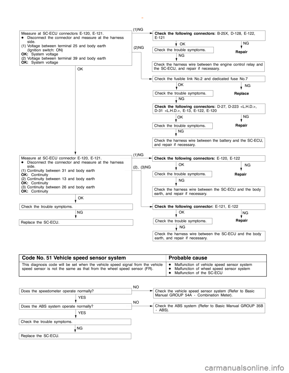
Code No. 27 SC-ECU power supply system (abnormal
voltage drop)Probable cause
This diagnosis code will be set if the SC-ECU power supply voltage drops below
a certain level.DMalfunction of battery
DMalfunction of harness or connector
DMalfunction of the SC-ECU
Caution
If the system voltage drops during inspection, this code will be output to indicate a current problem.
And correct problem diagnosis will not be possible. Before carrying out the following procedure,
check the battery and recharge it if necessary.
www.WorkshopManuals.co.uk
Purchased from www.WorkshopManuals.co.uk
Page 596 of 1839
MITSUBISHI SC-Troubleshooting MITSUBISHI SC-Troubleshooting13E-7
OK
NG
Repair
OK
Check the trouble symptoms.
NG
OKNG
Repair
OK
(1)NGCheck the following connectors:
B-25X, D-128, E-122,
E-121
NG
Check the harness wire between the engine control relay and
the SC-ECU, and repair if necessary. (2)NG
OK
Check the trouble symptoms.
NG
Replace
NG
Check the harness wire between the battery and the SC-ECU,
and repair if necessary.
Check the following connectors:
D-27, D-223
D-31
Measure at SC-ECU connectors E-120, E-121.
DDisconnect the connector and measure at the harness
side.
(1) Voltage between terminal 25 and body earth
(Ignition switch: ON)
OK:
System voltage
(2) Voltage between terminal 39 and body earth
OK:
System voltage
NG (1)NG
Check the harness wire between the SC-ECU and the body
earth, and repair if necessary.
Repair
NG
Replace the SC-ECU.
Check the trouble symptoms.
Check the following connectors:
E-120, E-122
NG
(2), (3)NG
Check the harness wire between the SC-ECU and the body
earth, and repair if necessary.
OK
NG
Repair
NGCheck the trouble symptoms.
Check the following connector:
E-121, E-122
OK
Check the trouble symptoms.
Measure at SC-ECU connector E-120, E-121.
DDisconnect the connector and measure at the harness
side.
(1) Continuity between 31 and body earth
OK:
Continuity
(2) Continuity between 13 and body earth
OK:
Continuity
(3) Continuity between 26 and body earth
OK:
Continuity
Check the trouble symptoms.
Check the fusible link No.2 and dedicated fuse No.7
Code No. 51 Vehicle speed sensor systemProbable cause
This diagnosis code will be set when the vehicle speed signal from the vehicle
speed sensor is not the same as that from the wheel speed sensor (FR).DMalfunction of vehicle speed sensor system
DMalfunction of wheel speed sensor system
DMalfunction of the SC-ECU
NG
Check the trouble symptoms.
Replace the SC-ECU.YES
NOCheck the vehicle speed sensor system (Refer to Basic
Manual GROUP 54A - Combination Meter).Does the speedometer operate normally?
YES
NOCheck the ABS system (Refer to Basic Manual GROUP 35B
- ABS).Does the ABS system operate normally?
www.WorkshopManuals.co.uk
Purchased from www.WorkshopManuals.co.uk