2000 MITSUBISHI MONTERO fuel
[x] Cancel search: fuelPage 854 of 1839

ENGINE AND EMISSION CONTROL -Emission Control System
<4M4-Vehicles with EGR>17-52
EMISSION CONTROL SYSTEM <4M4-VEHICLES WITH
EGR>
GENERAL INFORMATION
The electronically-controlled EGR system and the
fuel injection timing control system (load timer)
reduce the level of exhaust gases (NO
x).
ItemsNameSpecification
Exhaust emission
control systemExhaust gas recirculation system
DEGR valve
DEGR solenoid valve No.1
DEGR solenoid valve No.2Electronically-controlled EGR system
Single type
Duty cycle solenoid valve
ON-OFFsolenoid valve
SERVICE SPECIFICATIONS
ItemsStandard value
EGR solenoid valve No.1/No. 2 resistance (at 20_C)W36 - 44
www.WorkshopManuals.co.uk
Purchased from www.WorkshopManuals.co.uk
Page 950 of 1839

Page 952 of 1839

AUTOMATIC TRANSMISSION -Troubleshooting AUTOMATIC TRANSMISSION -Troubleshooting 23-51
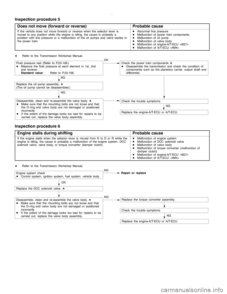
Inspection procedure 5
Does not move (forward or reverse)
Probable cause
If the vehicle does not move forward or reverse when the selector lever is
moved to any position while the engine is idling, thecause is probably a
problem with line pressure or a malfunction of the oil pumps and valve bodies in
the power train.DAbnormal line pressure
DMalfunction of power train components
DMalfunction of oil pump
DMalfunction of valve body
DMalfunction of engine-A/T-ECU <6G7>
DMalfunction of A/T-ECU<4M4>
LRefer to the Transmission Workshop Manual.
Fluid pressure test (Refer to P.23-106.)
DMeasure the fluid pressure at each element in 1st, 2nd
and reverse.
Standard value:Refer to P.23-106.OKCheck the power train components
L
DDisassemble the transmission and check the condition of
components such as the planetary carrier, output shaft and
differential.
NG
Replace the oil pumpassembly.
L
(The oilpump cannot be disassembled.)
Disassemble, clean and re-assemble the valve body.
L
DMake sure that the mounting bolts are not loose and that
the O-ring and valve body are notdamaged or positioned
incorrectly.
DIf the extent of thedamagelooks too bad for repairs to be
carried out, replace the valve body assembly.NG
NG
Check the trouble symptoms.
Replace the engine-A/T-ECU or A/T-ECU.
Inspection procedure 6
Engine stalls during shifting
Probable cause
If the enginestalls when the selector lever is moved from N to D or R while the
engine is idling, thecause is probably a malfunction of theenginesystem, DCC
solenoid valve, valve body, or torque converter (damper clutch).DMalfunction of enginesystem
DMalfunction of DCC solenoid valve
DMalfunction of valve body
DMalfunction of torque converter (malfunction of
damper clutch)
DMalfunction of engine-A/T-ECU <6G7>
DMalfunction of A/T-ECU<4M4>
LRefer to the Transmission Workshop Manual.
Engine system check
DControl system, ignition system, fuel system, vehicle bodyNG
Repair or replace
OK
Replace the DCC solenoid valve.
L
Disassemble, clean and re-assemble the valve body.
L
DMake sure that the mounting bolts are not loose and that
the O-ring and valve body are notdamaged or positioned
incorrectly.
DIf the extent of thedamagelooks too bad for repairs to be
carried out, replace the valve body assembly.NGReplace the torque converter assembly.
Check the trouble symptoms.
Replace the engine-A/T-ECU or A/T-ECU.NG
www.WorkshopManuals.co.uk
Purchased from www.WorkshopManuals.co.uk
Page 958 of 1839

Page 1353 of 1839

42-1
BODY
CONTENTS
HOOD3 ....................................
FENDER5 ..................................
FUEL FILLER DOOR6 .....................
WINDOW GLASS8 .........................
ADHESIVES 8.............................
SPECIAL TOOL 8.........................
WINDOW REPAIR 8.......................
WINDSHIELD 10..........................
QUARTER WINDOW GLASS 14...........
BACK DOOR GLASS 16..................
DOORS18 .................................
SERVICE SPECIFICATIONS 18............
SEALANT 18.............................
SPECIAL TOOLS 18......................
TROUBLESHOOTING 19..................ON-VEHICLE SERVICE 19................
Door Fit Adjustment 19.................
Door Window Glass Adjustment 19......
Defective Power Window Adjustment and
Replacement
20 .........................
Power Window Safety Mechanism Check 20..
Door Outside Handle Play Check 21.....
Power Window Operation Current
Check 21..............................
Circuit Breaker (Incorporated in the Power
Window Motor) Check 21...............
Door Inside Handle Play Check and
Adjustment 21..........................
DOOR ASSEMBLY 22.....................
DOOR TRIM AND WATERPROOF
FILM 24..................................
DOOR GLASS AND REGULATOR 30......
DOOR HANDLE AND LATCH 33..........
WINDOW GLASS RUNCHANNEL AND
DOOR OPENING WEATHERSTRIP 36.....
BACK DOOR39 ...........................
SERVICE SPECIFICATION 39.............
SEALANT 39.............................
SPECIAL TOOL 39.......................
TROUBLESHOOTING 39..................
CONTINUED ON NEXT PAGE
www.WorkshopManuals.co.uk
Purchased from www.WorkshopManuals.co.uk
Page 1358 of 1839

2
1
3
4 3
R em oval ste p s
A A"
"
AA
1. R iv e t
2 . Fuel fille r door panel asse m bly
3 . Fuel fille r door lo ck hook asse m bly
4 . Lid lo ck re le ase handle
D Heate r deck cro ss asse m bly
( R efe r to GRO UP 55.) D
AC in ve rte r (L ong wheelb ase )
( R efe r to GRO UP 54.)
5 . Fuel fille r door lo ck re le ase ca ble
Page 1460 of 1839

L
R em oval ste p s
D Rear flo or co nso le asse m bly (R efe r
t o P.5 2A -1 2.)
D CD pla ye ru nit (R efe rto G RO UP 54A .)
D Fro nt flo or co nso le
( R efe r to P.5 2A -1 2.)
1 . C ente r panel asse m bly
2 . C ente r dis p la y
3 . R adio and ta pe pla ye r
4 . M anual air co ndit io ner asse m bly
5 . G lo ve box sto pper
6 . G lo ve box asse m bly
7 . G lo ve box lo ck
8 . G lo ve box la m p sw it c h harn ess
c o nnecto r
9 . G lo ve box la m p sw it c h
1 0. G lo ve box la m p
1 1 . U pper glo ve box str ik e r
1 2. U pper glo ve box asse m bly
1 3. U pper glo ve box lid lo ck
1 4. Fro nt passe nger’s sid e air bag
m odule harn ess co nnecto r 1
5. In str u m ent panel sid e co ve r
1 6. A ir outle t asse m bly
1 7. M ete r beze l
1 8. C om bin atio n mete r asse m bly
D Hood opener le ve r
( R efe r to GRO UP 42.)
D Fuel lid opener le ve r
( R efe r to GRO UP 42.)
1 9. Low er panel
2 0. S w it c h panel
2 1. C olu m n co ve r
2 2. S ta y A
D Assis t grip (R efe r to P.5 2A -1 3,1 5.)
D Fro ntp illa rtr im (R efe rto P.5 2A -1 3,1 5.)
2 3. U nder co ve r asse m bly
2 4. S ta y B
2 5. C orn er lo w er panel
2 6. P hoto se nso r harn ess co nnecto r
D Ste erin g sh aft asse m bly bolt
( R efe r to GRO UP 37A .)
2 7. In str u m ent panel asse m bly
w
ww.W ork sh opM an uals .c o .u k
P urc h ased f r o m w ww.W ork sh opM an uals .c o .u k
Page 1572 of 1839

54A-2
CHASSIS
ELECTRICAL
CONTENTS
BATTERY 4
..............................
SERVICE SPECIFICATIONS 4..................
ON-VEHICLE SERVICE 4......................
Electrolyte Level and Specific Gravity Check 4..
Charging 5.................................
Battery Test 5...............................
IGNITION SWITCH AND IMMOBILIZER
SPECIAL TOOLS 6............................
TROUBLESHOOTING 6........................
IGNITION SWITCH AND
IMMOBILIZER-ECU 11.........................
IGNITION SWITCH AND IMMOBILIZER
<4D56> 14...............................
SPECIAL TOOLS 14...........................
TROUBLESHOOTING 14.......................
IGNITION SWITCH AND IMMOBILIZER-ECU
19 ............................................
COMBINATION METER 23................
SERVICE SPECIFICATIONS 23.................
SEALANTS 24................................
SPECIAL TOOLS 24...........................
TROUBLESHOOTING 24.......................
ON-VEHICLE SERVICE 30.....................
Speedometer Check 30......................
Tachometer Check 30........................
Fuel Gauge Unit Check 31....................Engine Coolant Temperature Gauge Unit Check
32 .........................................
COMBINATION METER 33.....................
HEADLAMP ASSEMBLY 36...............
SERVICE SPECIFICATIONS 36.................
SPECIAL TOOLS 36...........................
TROUBLESHOOTING 36.......................
ON-VEHICLE SERVICE 36.....................
Headlamp Aiming Adjustment 36..............
Luminance Measurement 38..................
Headlamp Bulb Replacement 39...............
HEADLAMP ASSEMBLY 40....................
FOG LAMPS 41..........................
SERVICE SPECIFICATIONS 41.................
SPECIAL TOOLS 41...........................
TROUBLESHOOTING 41.......................
ON-VEHICLE SERVICE 41.....................
Fog Lamp Aiming Check 41...................
FOG LAMPS 44...............................
SIDE TURN-SIGNAL LAMPS 45...........
SPECIAL TOOLS 45...........................
SIDE TURN-SIGNAL LAMPS 46................
ROOM LAMP 46.........................
TROUBLESHOOTING 46.......................
CONTINUED ON NEXT PAGE
www.WorkshopManuals.co.uk
Purchased from www.WorkshopManuals.co.uk