2000 MITSUBISHI MONTERO fuel
[x] Cancel search: fuelPage 735 of 1839

INTAKE AND EXHAUST -General Information/Service Specifications/Sealant15-3
At starting and driving at low speed, the duty control
value of the variable geometry solenoid valve is
increased to apply the vacuum pressure of the
vacuum pump to the variable geometry actuator.
Applying the vacuum pressure to the variable
geometry actuator pulls the actuator rod so that
it can move towards the direction of closing the
variable nozzle of the variable geometry
turbocharger. As closing the nozzle reduces the
exhaust gas mass, the speed of exhaust gas flow
will be increased and efficiency will be improved.
Since the characteristic of boost pressure becomes
a low speed type, boost pressure will suddenly
rise from low speed.
At driving at high speed, the duty control value
of the variable geometry solenoid valve is
decreased to reduce the vacuum pressure from
the vacuum pump so that the actuator rod can
return to the deactivated status and move towards
the direction of opening the nozzle of the variable
geometry turbocharger.Opening the nozzle allows the characteristic of
boost pressure to become a high speed type so
that the appropriate boost pressure can be
maintained.
Therefore, boost pressure can be controlled by
appropriate duty control of the variable geometry
solenoid valve. The engine-ECU calculates the
correct boost pressure based on the engine speed
and fuel injection amount. Furthermore, the duty
control of the variable geometry solenoid valve is
given feedback of the signals from the variable
geometry control pressure sensor and the boost
pressure sensor so that the variable nozzle opening
angle of the variable geometry turbocharger can
be quickly adjusted to obtain the desired boost
pressure.
SERVICE SPECIFICATIONS
ItemsStandard value
Variable geometry actuator activation vacuum
(Approximately 1 mm stroke) kPaApproximately 10.5 - 12.5
Variable geometry solenoid valve coil resistance
(at 20°C)Ω29 - 35
SEALANT
ItemSpecified sealantRemarks
Thread of the intake manifold mounting
bolts3M Stud Locking No.4170 or equivalentAnaerobic sealant
www.WorkshopManuals.co.uk
Purchased from www.WorkshopManuals.co.uk
Page 801 of 1839

ENGINE ELECTRICAL -Glow System <4D5-StepIII>16-1
GROUP 16
ENGINE ELECTRICAL
GLOW SYSTEM <4D5-STEPIII>
GENERAL
OUTLINE OF CHANGE
Glow system control is now carried out by the engine-ECU to correspond to the adoption of an
electronically-controlled fuel injection system.
Refer to GROUP 13E - Troubleshooting for details on measuring the ECU terminal voltage as a result
of this.
www.WorkshopManuals.co.uk
Purchased from www.WorkshopManuals.co.uk
Page 804 of 1839

17-2
EVAPORATIVE EMISSION CONTROL
SYSTEM 36..............................
General Information 36......................
System Diagram 36.........................
Component Location 36......................
Purge Control System Check 37..............
Purge Port Vacuum Check 37................
Purge Control Solenoid Valve Check 38.......
EXHAUST GAS RECIRCULATION (EGR)
SYSTEM 39..............................
General Information 39......................
Operation 39................................
System Diagram 39.........................
Component Location 39......................
Exhaust Gas Recirculation (EGR) Control
System Check 40...........................
EGR Valve (Stepper Motor) Check 40........
EGR VALVE 42...........................
CANISTER 43............................
CATALYTIC CONVERTER 44..............
General Information 44......................
EMISSION CONTROL SYSTEM
<4D5> 45.............................
GENERAL INFORMATION 45..............
SERVICE SPECIFICATIONS 45............
SEALANT 45.............................
SPECIAL TOOL 45.......................
EXHAUST GAS RECIRCULATION (EGR)
SYSTEM 46..............................
General Information 46......................
System Diagram 46.........................
Component Location 46......................
Function Check 47..........................
EGR Solenoid Valve Operation Check 47.....
EGR Solenoid Valve Resistance Check 48....
Lever Position Sensor (LPS) Adjustment 48...
Engine Speed Sensor Check 49..............
Engine Coolant Temperature Sensor
Check 49...................................
CHECK AT THE GLOW & EGR CONTROL
UNIT 51..................................
EMISSION CONTROL SYSTEM
<4M4-VEHICLES WITH EGR> 52........
GENERAL INFORMATION 52..............
SERVICE SPECIFICATIONS 52............
EXHAUST GAS RECIRCULATION (EGR)
SYSTEM 53..............................
General Information 53......................
System Diagram 53.........................
Component Location 53......................
Function Check 54..........................
EGR Solenoid Valve Operation Check 54.....
EGR Solenoid Valve Resistance Check 55....
Accelerator Pedal Position Sensor (APS),
Engine Coolant Temperature Sensor, Intake
Air Temperature Sensor, Fuel Temperature
Sensor Check 55............................
Check at Engine-ECU 55....................
CATALYTIC CONVERTER 55..............
General Information 55......................
www.WorkshopManuals.co.uk
Purchased from www.WorkshopManuals.co.uk
Page 816 of 1839

ENGINE AND EMISSION CONTROL -Auto-cruise Control System17-14
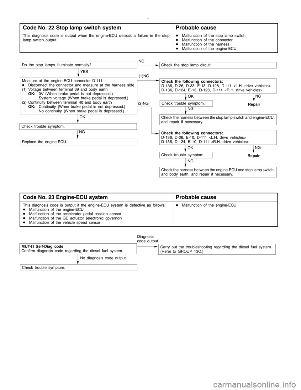
Code No. 22 Stop lamp switch systemProbable cause
This diagnosis code is output when the engine-ECU detects a failure in the stop
lampswitch output.DMalfunction of the stoplampswitch
DMalfunction of the connector
DMalfunction of the harness
DMalfunction of the engine-ECU
(2)NG
NG
Check the harness between the engine-ECU and stoplampswitch,
and body earth, and repair if necessary.
NG
Repair
OK
Check trouble symptom.
Measure at the engine-ECU connector D-111.
DDisconnect the connector and measure at the harness side.
(1) Voltage between terminal 39 and body earth
OK:0V (When brakepedal is not depressed.)
System voltage (When brakepedal is depressed.)
(2) Continuity between terminal 40 and body earth
OK:Continuity (When brakepedal is not depressed.)
No continuity (When brakepedal is depressed.)NO
Do the stop lamps illuminate normally?
OK
Check trouble symptom.
Check the following connectors:
D-136, D-26, D-33, E-13, D-128, D-111
D-136, D-124, E-13, D-128, D-111
OK
Check trouble symptom.
NG
Check the harness between the stoplampswitch and engine-ECU,
and repair if necessary.NG
Repair
Check the stoplampcircuit.
YES
(1)NG
Check the following connectors:
D-136, D-26, E-10, D-111
D-136, D-124, E-10, D-111
Replace the engine-ECU.
Code No. 23 Engine-ECU systemProbable cause
This diagnosis code is output if the engine-ECU system is defective as follows:
DMalfunction of the engine-ECU
DMalfunction of the accelerator pedal positionsensor
DMalfunction of the GE actuator (electronic governor)
DMalfunction of the vehicle speed sensorDMalfunction of the engine-ECU
MUT-
IISelf-Diag code
Confirm diagnosis code regarding the diesel fuel system.Diagnosis
code outputCarry out the troubleshooting regarding the diesel fuel system.
(Refer to GROUP 13C.)
No diagnosis code output
Check trouble symptom.
www.WorkshopManuals.co.uk
Purchased from www.WorkshopManuals.co.uk
Page 822 of 1839

ENGINE AND EMISSION CONTROL -Auto-cruise Control SystemENGINE AND EMISSION CONTROL -Auto-cruise Control System17-20
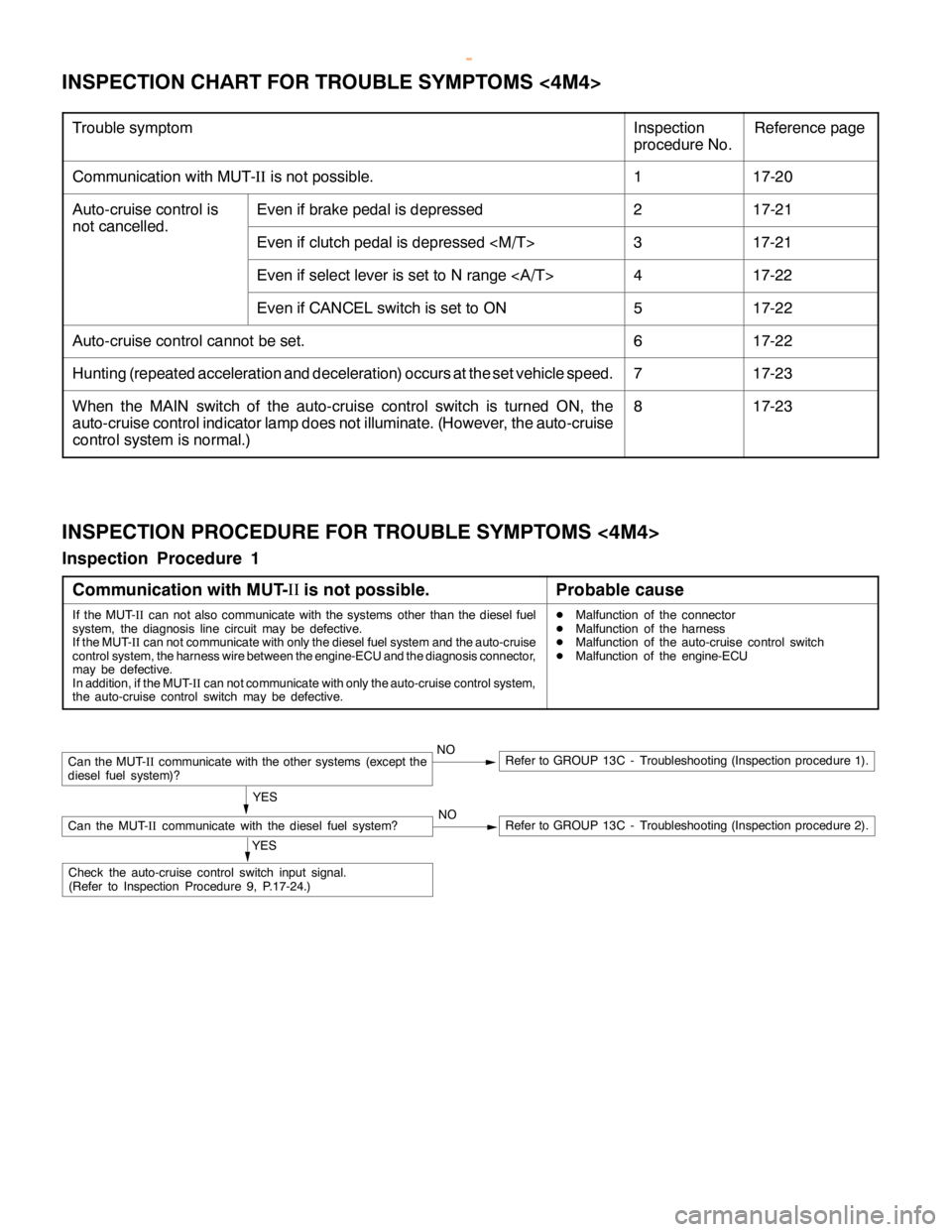
INSPECTION CHART FOR TROUBLE SYMPTOMS <4M4>
Trouble symptomInspection
procedure No.Reference page
Communication with MUT-IIis not possible.117-20
Auto-cruise control isEven if brake pedal is depressed217-21
not cancelled.
Even if clutch pedal is depressed
Even if select lever is set to N range417-22
Even if CANCEL switch is set to ON517-22
Auto-cruise control cannot be set.617-22
Hunting (repeated acceleration and deceleration) occurs at the set vehicle speed.717-23
When the MAIN switch of the auto-cruise control switch is turned ON, the
auto-cruise control indicator lamp does not illuminate. (However, the auto-cruise
control system is normal.)817-23
INSPECTION PROCEDURE FOR TROUBLE SYMPTOMS <4M4>
Inspection Procedure 1
Communication with MUT-II
is not possible.
Probable cause
If the MUT-
IIcan not also communicate with the systems other than the diesel fuel
system, the diagnosis line circuit may be defective.
If the MUT-
IIcan not communicate with only the diesel fuel system and the auto-cruise
control system, the harness wire between the engine-ECU and the diagnosis connector,
may be defective.
In addition, if the MUT-
IIcan not communicate with only the auto-cruise control system,
the auto-cruise control switch may be defective.DMalfunction of the connector
DMalfunction of the harness
DMalfunction of the auto-cruise control switch
DMalfunction of the engine-ECU
NORefer to GROUP 13C - Troubleshooting (Inspection procedure 2).
Can the MUT-
IIcommunicate with the other systems (except the
diesel fuel system)?NORefer to GROUP 13C - Troubleshooting (Inspection procedure 1).
YES
Can the MUT-
IIcommunicate with the diesel fuel system?
YES
Check the auto-cruise control switch input signal.
(Refer to Inspection Procedure 9, P.17-24.)
www.WorkshopManuals.co.uk
Purchased from www.WorkshopManuals.co.uk
Page 824 of 1839

ENGINE AND EMISSION CONTROL -Auto-cruise Control System17-22
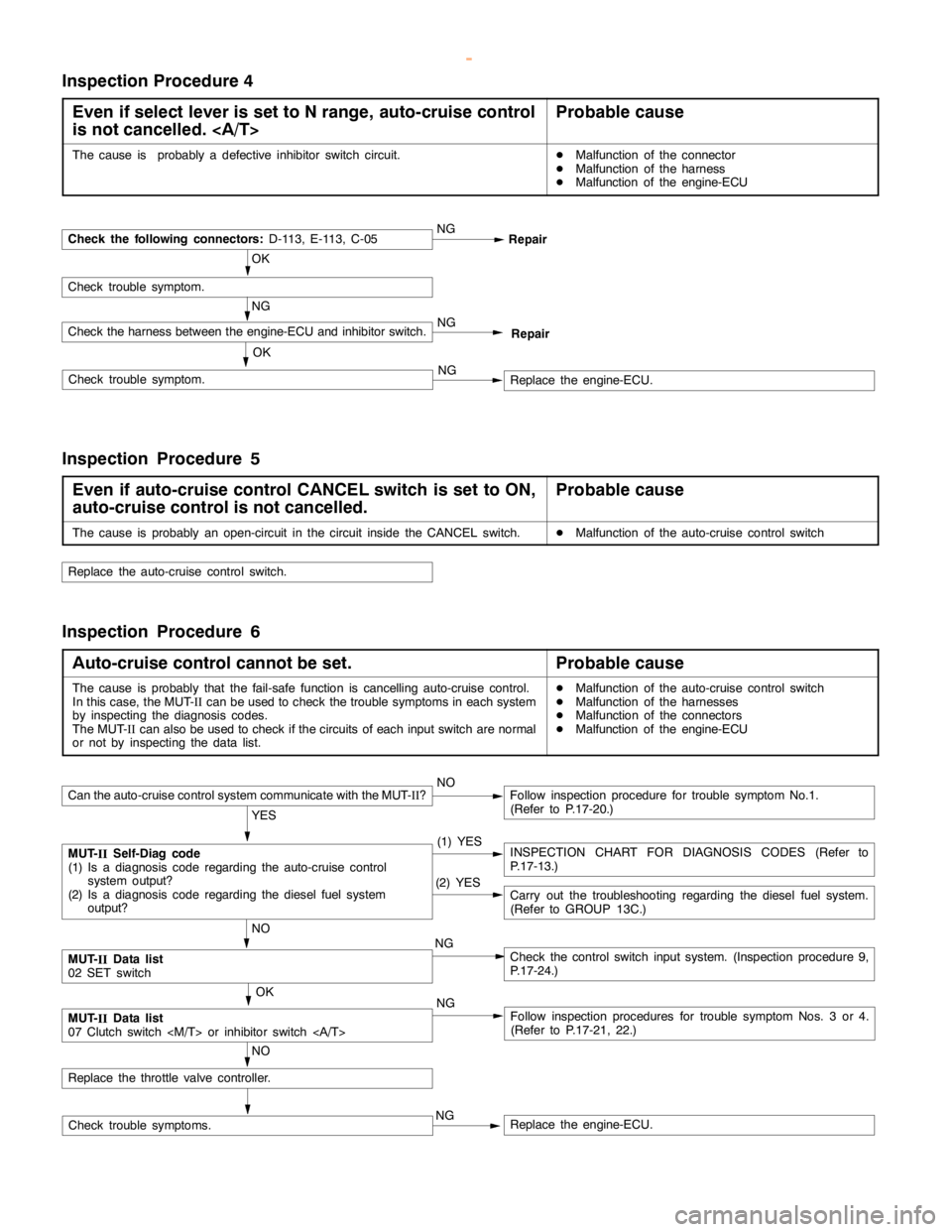
Inspection Procedure 4
Even if select lever is set to N range, auto-cruise control
is not cancelled.
Probable cause
The cause is probably a defective inhibitor switch circuit.DMalfunction of the connector
DMalfunction of the harness
DMalfunction of the engine-ECU
OK
Check trouble symptom.
Check the following connectors:D-113, E-113, C-05NG
Repair
NG
Check the harness between the engine-ECU and inhibitor switch.
NG
Replace the engine-ECU. OKCheck trouble symptom.NG
Repair
Inspection Procedure 5
Even if auto-cruise control CANCEL switch is set to ON,
auto-cruise control is not cancelled.
Probable cause
The cause is probably an open-circuit in the circuit inside the CANCEL switch.DMalfunction of the auto-cruise control switch
Replace the auto-cruise control switch.
Inspection Procedure 6
Auto-cruise control cannot be set.
Probable cause
The cause is probably that the fail-safe function is cancelling auto-cruise control.
In this case, the MUT-
IIcan be used to check the trouble symptoms in each system
by inspecting the diagnosis codes.
The MUT-
IIcan also be used to check if the circuits of each input switch are normal
or not by inspecting the data list.DMalfunction of the auto-cruise control switch
DMalfunction of the harnesses
DMalfunction of the connectors
DMalfunction of the engine-ECU
Check trouble symptoms.
Can the auto-cruise control system communicate with the MUT-
II?NOFollow inspection procedure for trouble symptom No.1.
(Refer to P.17-20.)
YES
MUT-
IISelf-Diag code
(1) Is a diagnosis code regarding the auto-cruise control
system output?
(2) Is a diagnosis code regarding the diesel fuel system
output?(1) YESINSPECTION CHART FOR DIAGNOSIS CODES (Refer to
P.17-13.)
NO
MUT-
IIData list
02 SET switchNGCheck the control switch input system. (Inspection procedure 9,
P.17-24.)
OK
MUT-
IIData list
07 Clutch switch
NG
NO
Replace the throttle valve controller.(2) YES
Carry out the troubleshooting regarding the diesel fuel system.
(Refer to GROUP 13C.)
Follow inspection procedures for trouble symptom Nos. 3 or 4.
(Refer to P.17-21, 22.) NG
Replace the engine-ECU.
www.WorkshopManuals.co.uk
Purchased from www.WorkshopManuals.co.uk
Page 825 of 1839

ENGINE AND EMISSION CONTROL -Auto-cruise Control System17-23
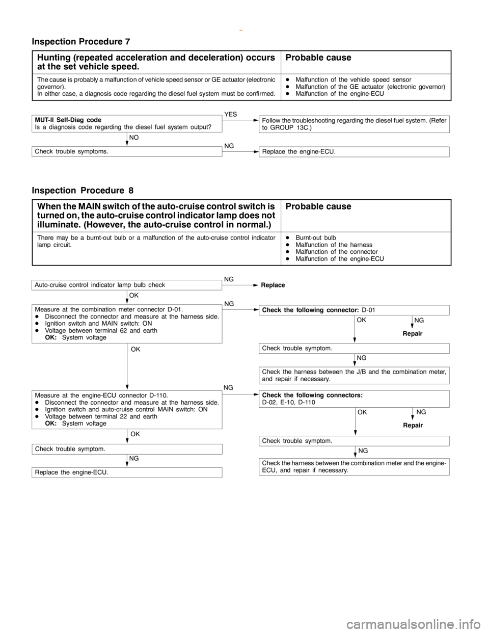
Inspection Procedure 7
Hunting (repeated acceleration and deceleration) occurs
at the set vehicle speed.
Probable cause
The cause is probably a malfunction of vehicle speed sensor or GE actuator (electronic
governor).
In either case, a diagnosis code regarding the diesel fuel system must be confirmed.DMalfunction of the vehicle speed sensor
DMalfunction of the GE actuator (electronic governor)
DMalfunction of the engine-ECU
MUT-II Self-Diag code
Is a diagnosis code regarding the diesel fuel system output?YES
NO
Check trouble symptoms.NGReplace the engine-ECU.
Follow the troubleshooting regarding the diesel fuel system. (Refer
to GROUP 13C.)
Inspection Procedure 8
When the MAIN switch of the auto-cruise control switch is
turned on, the auto-cruise control indicator lamp does not
illuminate. (However, the auto-cruise control in normal.)
Probable cause
There may be a burnt-out bulb or a malfunction of the auto-cruise control indicator
lampcircuit.DBurnt-out bulb
DMalfunction of the harness
DMalfunction of the connector
DMalfunction of the engine-ECU
OK
Auto-cruise control indicatorlamp bulbcheckNG
Replace
NG
Repair
OK
NG
OK
Check trouble symptom.
NG
Check the harness between the J/B and the combination meter,
and repair if necessary.
Check the following connectors:
D-02, E-10, D-110
OK
Check trouble symptom.
NG
Repair
NG
Replace the engine-ECU.NG
Measure at the engine-ECU connector D-110.
DDisconnect the connector and measure at the harness side.
DIgnition switch and auto-cruise control MAIN switch: ON
DVoltage between terminal 22 and earth
OK:System voltage
Measure at the combination meter connector D-01.
DDisconnect the connector and measure at the harness side.
DIgnition switch and MAIN switch: ON
DVoltage between terminal 62 and earth
OK:System voltageCheck the following connector:D-01
NG
Check the harness between the combination meter and the engine-
ECU, and repair if necessary. OK
Check trouble symptom.
www.WorkshopManuals.co.uk
Purchased from www.WorkshopManuals.co.uk
Page 833 of 1839

ENGINE AND EMISSION CONTROL -Emission Control System <6G7>17-31
EMISSION CONTROL SYSTEM <6G7>
GENERAL INFORMATION
The emission control system consists of the following subsystems:
DCrankcase emission control system
DEvaporative emission control system
DExhaust emission control system
ItemsNameSpecification
Crankcase emission
control systemPositive crankcase ventilation (PCV) valveVariable flow type
(Purpose: HC reduction)
Evaporative emission
control systemCanister
Purge control solenoid valveEquipped
Duty cycle type solenoid valve
(Purpose: HC reduction)
Exhaust emission
control systemAir-fuel ratio control device - GDI systemOxygen sensor feedback type
(Purpose: CO, HC, NOx reduction)
Exhaust gas recirculation system
DEGR valveEquipped
Stepper motor type
(Purpose: NOx reduction)
Catalytic converterMonolith type
(Purpose: CO, HC, NOx reduction)
EMISSION CONTROL DEVICE REFERENCE TABLE
Related partsCrankcase
emission
control
systemEvaporative
emission
control
systemAir/fuel
ratio
control
systemCatalytic
converterExhaust
gas
recirculation
systemReference
page
PCV valve´17-35
Purge control solenoid valve´17-38
GDI system component´´GROUP
13A
Catalytic converter´17-44
EGR valve´17-40
www.WorkshopManuals.co.uk
Purchased from www.WorkshopManuals.co.uk