2000 MITSUBISHI MONTERO fuel
[x] Cancel search: fuelPage 1579 of 1839

CHASSIS ELECTRICAL-Ignition Switch and Immobilizer
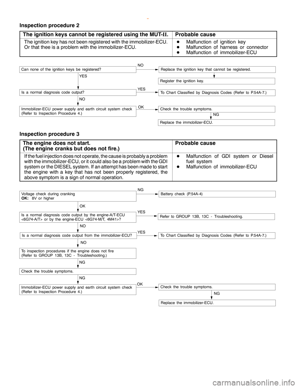
Inspection procedure 2
The ignition keys cannot be registered using the MUT-II.
Probable cause
The ignition key has not been registered with the immobilizer-ECU.
Or that thee is a problem with the immobilizer-ECU.D
Malfunction of ignition key
D
Malfunction of harness or connector
D
Malfunction of immobilizer-ECU
Register the ignition key.
YES
NO YESIs a normal diagnosis code output?
NOCan none of the ignitionkeys beregistered?Replace the ignition key that cannot be registered.
To Chart Classified by Diagnosis Codes (Refer to P.54A-7.)
OKImmobilizer-ECU power supply and earth circuit system check
(Refer to Inspection Procedure 4.)
NG
Replace the immobilizer-ECU.
Check the trouble symptoms.
Inspection procedure 3
The engine does not start.
(The engine cranks but does not fire.)
Probable cause
If the fuel injection does not operate, the cause is probably a problem
with the immobilizer-ECU, or it could also be a problem with the GDI
system or the DIESEL system. If an attempt has been made to start
the engine with a key that has not been properly registered, the
above symptom is a sign of normal operation.D
Malfunction of GDI system or Diesel
fuel system
D
Malfunction of immobilizer-ECU
NGBattery check (P.54A-4)
YES
NO
Refer to GROUP 13B, 13C - Troubleshooting.YES
NO
To Chart Classified by Diagnosis Codes (Refer to P.54A-7.)Is a normal diagnosis code output from the immobilizer-ECU?
OK
Voltage check during cranking
OK:8V or higher
NG
OKImmobilizer-ECU power supply and earth circuit system check
(Refer to Inspection Procedure 4.)
NG
Replace the immobilizer-ECU.
Check the trouble symptoms.
Check the trouble symptoms.
NG
To inspection procedures if the enginedoes not fire
(Refer to GROUP 13B, 13C - Troubleshooting.)
Is a normal diagnosis code output by the engine-A/T-ECU
<6G74-A/T> or by the engine-ECU <6G74-M/T, 4M41>?
www.WorkshopManuals.co.uk
Purchased from www.WorkshopManuals.co.uk
Page 1587 of 1839

CHASSIS ELECTRICAL-Ignition Switch and Immobilizer <4D56>54A-17
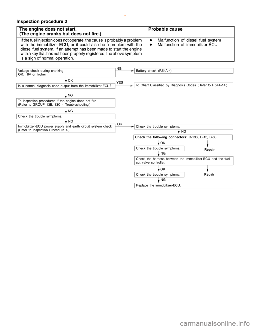
Inspection procedure 2
The engine does not start.
(The engine cranks but does not fire.)
Probable cause
If the fuel injection does not operate, the cause is probably a problem
with the immobilizer-ECU, or it could also be a problem with the
diesel fuel system. If an attempt has been made to start the engine
with a key that has not been properly registered, the above symptom
is a sign of normal operation.D
Malfunction of diesel fuel system
D
Malfunction of immobilizer-ECU
NGBattery check (P.54A-4)
YES
NOTo Chart Classified by Diagnosis Codes (Refer to P.54A-14.)Is a normal diagnosis code output from the immobilizer-ECU?
OK
Voltage check during cranking
OK:8V or higher
NG
Immobilizer-ECU power supply and earth circuit system check
(Refer to Inspection Procedure 4.)
Check the trouble symptoms.
NG
To inspection procedures if the enginedoes not fire
(Refer to GROUP 13B, 13C - Troubleshooting.)
OK
Check the trouble symptoms.
NG
OK
NG
Replace the immobilizer-ECU.
Check the trouble symptoms.
OK
Check the trouble symptoms.
NG
Repair
Check the harness between the immobilizer-ECU and the fuel
cut valve controller.
Repair
Check the following connectors:D-133, D-13, B-03
www.WorkshopManuals.co.uk
Purchased from www.WorkshopManuals.co.uk
Page 1593 of 1839

CHASSIS ELECTRICAL-Combination Meter54A-23
COMBINATION METER
SERVICE SPECIFICATIONS
ItemStandard valueLimit
Speedometer indication rangeAt 20 km/h18 - 23–
km/hAt 40 km/h37 - 45–
At 80 km/h75 - 88–
At 120 km/h113 - 132–
At 160 km/h150 - 176–
Speedometer needle swing km/h (when driving at 35 km/h or higher)–±3
Tachometer indication errorWhen engine speed is 700 r/min±120–
r/minWhen engine speed is 2,000 r/minPetrol- 175+225–
Diesel±175–
When engine speed is 3,000 r/minPetrol- 175+300–
Diesel±225–
When engine speed is 4,000 r/minPetrol- 225+375–
Diesel±300–
When engine speed is 4,750 r/min
When engine speed is 5,000 r/min
When engine speed is 6,000 r/min
Fuel gauge unit standardF position3–
resistance valueWE position11 0–
Fuel gauge unit float heightF position11.9–
mmE position195.2–
Engine coolant temperature gauge unit standard resistance valueW104±13.5–
Combination meter internal62 - 11 (IG power supply - earth)1MWor more–
resistance valueW62 - 25 (IG power supply - earth)1MWor more–(Measured at connector D-38
and connector D-40)
62 - 63 (IG power supply - fuel gauge)1MWor more–
62 - 64 (IG power supply - engine coolant
temperature gauge)1MWor more–
63 - 11 (fuel gauge - earth)180–
63 - 25 (fuel gauge - earth)180–
64 - 11 (engine coolant temperature gauge - earth)210–
64 - 25 (engine coolant temperature gauge - earth)210–
67 - 11 (battery power supply - earth)1MWor more–
67 - 25 (battery power supply - earth)1MWor more–
67 - 63 (battery power supply - fuel gauge)1MWor more–
67 - 64 (battery power supply - engine coolant
temperature gauge)1MWor more–
www.WorkshopManuals.co.uk
Purchased from www.WorkshopManuals.co.uk
Page 1595 of 1839

CHASSIS ELECTRICAL-Combination Meter CHASSIS ELECTRICAL-Combination Meter54A-25
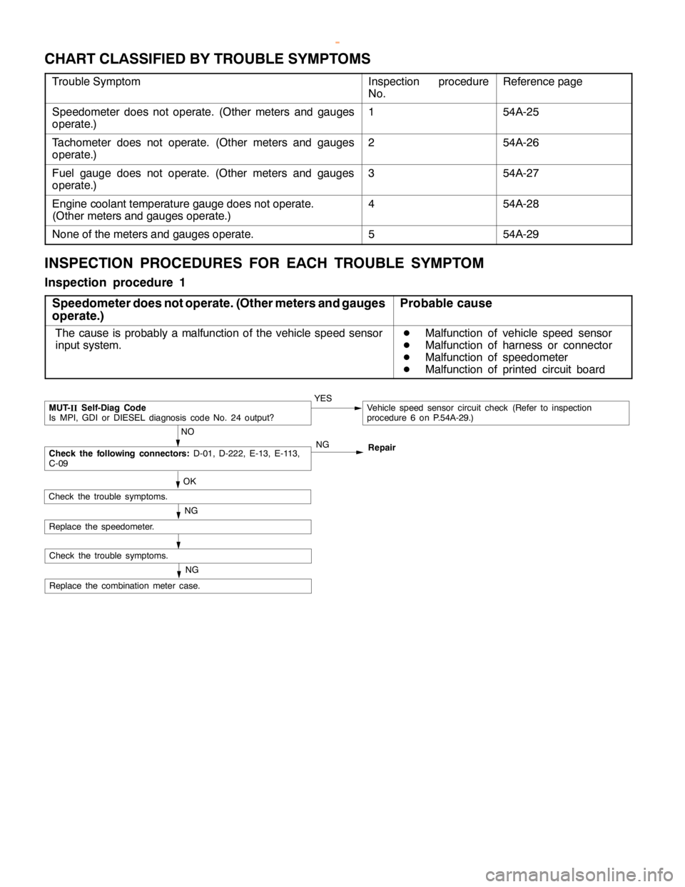
CHART CLASSIFIED BY TROUBLE SYMPTOMS
Trouble SymptomInspection procedure
No.Reference page
Speedometer does not operate. (Other meters and gauges
operate.)154A-25
Tachometer does not operate. (Other meters and gauges
operate.)254A-26
Fuel gauge does not operate. (Other meters and gauges
operate.)354A-27
Engine coolant temperature gauge does not operate.
(Other meters and gauges operate.)454A-28
None of the meters and gauges operate.554A-29
INSPECTION PROCEDURES FOR EACH TROUBLE SYMPTOM
Inspection procedure 1
Speedometer does not operate. (Other meters and gauges
operate.)
Probable cause
The cause is probably a malfunction of the vehicle speed sensor
input system.D
Malfunction of vehicle speed sensor
D
Malfunction of harness or connector
D
Malfunction of speedometer
D
Malfunction of printed circuit board
NO
MUT-
IISelf-Diag Code
Is MPI, GDI or DIESEL diagnosis code No. 24 output?YESVehicle speed sensor circuit check (Refer to inspection
procedure 6 on P.54A-29.)
OK
Replace the combination meter case.
NG
Check the trouble symptoms.
NGCheck the following connectors:D-01, D-222, E-13, E-113,
C-09Repair
NG
Check the trouble symptoms.
Replace the speedometer.
www.WorkshopManuals.co.uk
Purchased from www.WorkshopManuals.co.uk
Page 1604 of 1839

T
e rm in aln am e S
ta ndard va l-
u e 6
2 -11 I
G pow er su pply -Earth 1
M W or m ore 6
2 -25 I
G pow er su pply -Earth 1
M W or m ore 6
2 -63 I
G pow er su pply -Fuelg auge 1
M W or m ore 6
2 -64 I
G pow er su pply -Engin e co ola nt
t e m pera tu re gauge 1
M W or m ore 6
3 -11 F
uelg auge -Earth 1
80 W F
uelg auge -Earth 1
80 W E
ngin e co ola ntte m pera tu re gauge -
E arth 2
10 W E
ngin e co ola ntte m pera tu re gauge -
E arth 2
10 W B
atte ry pow er su pply -Earth 1
M W or m ore 6
7 -25 B
atte ry pow er su pply -Earth 1
M W or m ore 6
7 -63 B
atte ry pow er su pply -Fuelg auge 1
M W or m ore 6
7 -64 B
atte ry pow er su pply -Engin e
c o ola nt te m pera tu re gauge 1
M W or m ore D
-3 8
w
ww.W ork sh opM an uals .c o .u k
P urc h ased f r o m w ww.W ork sh opM an uals .c o .u k
Page 1624 of 1839

CHASSIS ELECTRICAL -Clock or Center Display54A-54
BEFORE REMOVING THE BATTERY
The Center display has a large amount of data unique to the vehicle in its memory. When the battery
cable is disconnected, that memory is affected as shown in the table below. Accordingly, it is necessary
to make sure that you take notes of important information before disconnecting the battery cable.
FunctionInput function/memoryWhen battery cable is disconnected
Clock set on displayCurrent timeRetains data for approx. 1 hour
Vehicle model setShort (3-door models)/long (5-door
models)Retains data for approx. 1 hour
Brightness set for displayPosition set on displayRetains data for approx. 1 hour
Unit set for trip computerkm or mile, L/100km or mpg or km/L
Average vehicle speed after resetRetains data for approx. 1 hour
Average vehicle speed on displayAverage vehicle speed after resetRetains data for approx. 1 hour
Average fuel consumption on displayAverage fuel consumption after resetRetains data for approx. 1 hour
Cruising range on displayCruising range, fuel economyRetains data for approx. 1 hour
Outside temperature on displayOutside temperature after the ignition
switch is turned to the OFF(LOCK)
position.Retains data for approx. 1 hour
* The outside temperature sensor
is located near the engine.
Therefore, incorrectly high
temperature may be displayed
when the battery cable is
reconnected within one hour.
DIAGNOSIS FUNCTION FOR CENTER DISPLAY
Center display has the following diagnosis function:
FunctionContents
Service functionThere are the following 4 diagnosis modes available
1. Check of vehicle informationThe vehicle, short (3-door models)/long (5-door models) set
2. Check of LCD segmentsThe LCD segments for display available to light on or not
3. Check of sensorsOutside temperature, voltage of fuel gauge unit, system voltage, fuel amount
remains, fuel economy calculated after supply of fuel
4. Check of units connected into
the center displayThe units connected on display
Voltage (%) on terminal for MUT-II
Vehicle speed signal sent by engine-ECU
Oscillating signal
www.WorkshopManuals.co.uk
Purchased from www.WorkshopManuals.co.uk
Page 1630 of 1839

CHASSIS ELECTRICAL -Clock or Center Display54A-60
Terminal
No.Input/
OutputSignal symbolTerminal
voltage (V)Wiring harness
problemTrouble symptom caused by wiring
harness problem
Open
circuitShort
circuit
15Input/
OutputKHi: System
voltage
Lo: 0-1ExistsExistsValues on trip information screen (average
vehicle speed, fuel consumption and
cruising distance) are abnormal. Commu-
nication is impossible between the
engine-ECU and the MUT-II.
16------
17Input/
OutputM-BUSY
(AUDIO)Hi: 4-5
Lo: 0-1ExistsExistsAudio display does not appear. Panel
switch cannot be operated for audio unit.
Nighttime illumination does not appear for
audio unit.
18-SHIELD-GND----
19Input/
OutputM-BUSY
(A/C)Hi: 4-5
Lo: 0-1ExistsExistsA/C display does not appear.
Outside air temperature does not appear
20-SHIELD-GND----
21, 22------
23InputEX-TEMPExistsExistsOutside air temperature does not appear.
24InputILL+Hi: System
voltageExists-Nighttime illumination does not appear for
audio units.
Lo: 0-1
-ExistsBlown multipurpose fuse.
25InputACC (ACCSystem volt-Exists-Screen display does not appear.
power supply)age
-ExistsBlown multipurpose fuse.
26Input+BSystem volt-Exists-Screen display does not appear.
age
-ExistsBlown multipurpose fuse.
27InputVSSHi: System
voltage
Lo: 0-1ExistsExistsAbnormal outside air temperature ap-
pears.
(only diesel-powered vehicles)
28-GND (earth)-Exists-Screen display does not appear.
29, 30------
31-GND-TEMPExistsExistsOutside air temperature does not appear.
32InputILL -ExistsExistsThe display screen can not be dimmed.
33InputFUEL GAUGE-ExistsAbnormal cruising distance appears.
34, 35------
36InputIG1Hi: System
voltageExists-Communication with engine-ECU is im-
possible. Abnormal driving data values
appear.
-ExistsCommunication with engine-ECU is im-
possible. Abnormal driving data values
appear. Blown multipurpose fuse.
www.WorkshopManuals.co.uk
Purchased from www.WorkshopManuals.co.uk
Page 1631 of 1839

CHASSIS ELECTRICAL -Clock or Center Display54A-61
INSPECTION CHART CLASSIFIED BY TROUBLE SYMPTOMS
Related unitTrouble SymptomInspection pro-
cedure No.Reference
page
Malfunction of center
display, related sen-No display appears after the ignition key is turned to the
ACC position.154A-62
sors, and wiring har-
nesses
Outside air temperature does not appear or abnormal
outside air temperature appears.254A-62
Abnormal vehicle speed is displayed on the service
mode.354A-63
Abnormal driving data are displayed:
D
Abnormal average fuel consumption (momentary
fuel consumption) and average vehicle speed
D
Abnormal cruising distance454A-64
Clock runs fast or slow.554A-64
The display screen is dim.654A-65
Air conditioning display does not apper.754A-66
www.WorkshopManuals.co.uk
Purchased from www.WorkshopManuals.co.uk