Page 7 of 1111
CH0086
Correct Wrong
AC0WB±01
I03853
GS 400:A
B
P10652
GS 300:
Type A
Type BAB
AB AC±14
± AIR CONDITIONINGDRIVE BELT
2699 Author�: Date�:
2000 LEXUS GS300/GS400 (RM718U)
DRIVE BELT
ON±VEHICLE INSPECTION
1. INSPECT DRIVE BELT'S INSTALLATION CONDITION
Check that the drive belt fits properly in the ribbed grooves.
2. INSPECT DRIVE BELT TENSION
Check that the arrow mark on the belt tensioner falls within area
ºAº of the scale.
If it is out side area ºAº, replace the drive belt.
HINT:
When a new belt is installed, it should be lie within area B.
Page 8 of 1111
AC0WC±01
I03854
GS300:
Turn
I03855
GS400:
± AIR CONDITIONINGDRIVE BELT
AC±15
2700 Author�: Date�:
2000 LEXUS GS300/GS400 (RM718U)
REMOVAL
1. GS 300:
REMOVE DRIVE BELT
Loosen the drive belt tension by turning the drive belt tensioner
clockwise and remove the drive belt.
2. GS 400:
REMOVE DRIVE BELT
Loosen the drive belt tension by turning the drive belt tensioner
counterclockwise and remove the drive belt.
Page 9 of 1111
AC0WD±01
AC±16
± AIR CONDITIONINGDRIVE BELT
2701 Author�: Date�:
2000 LEXUS GS300/GS400 (RM718U)
INSTALLATION
Installation is in the reverse order of removal (See page AC±15).
AFTER INSTALLATION, CHECK DRIVE BELT'S INSTALLATION CONDITION
Page 36 of 1111
AC0WU±01
I02379
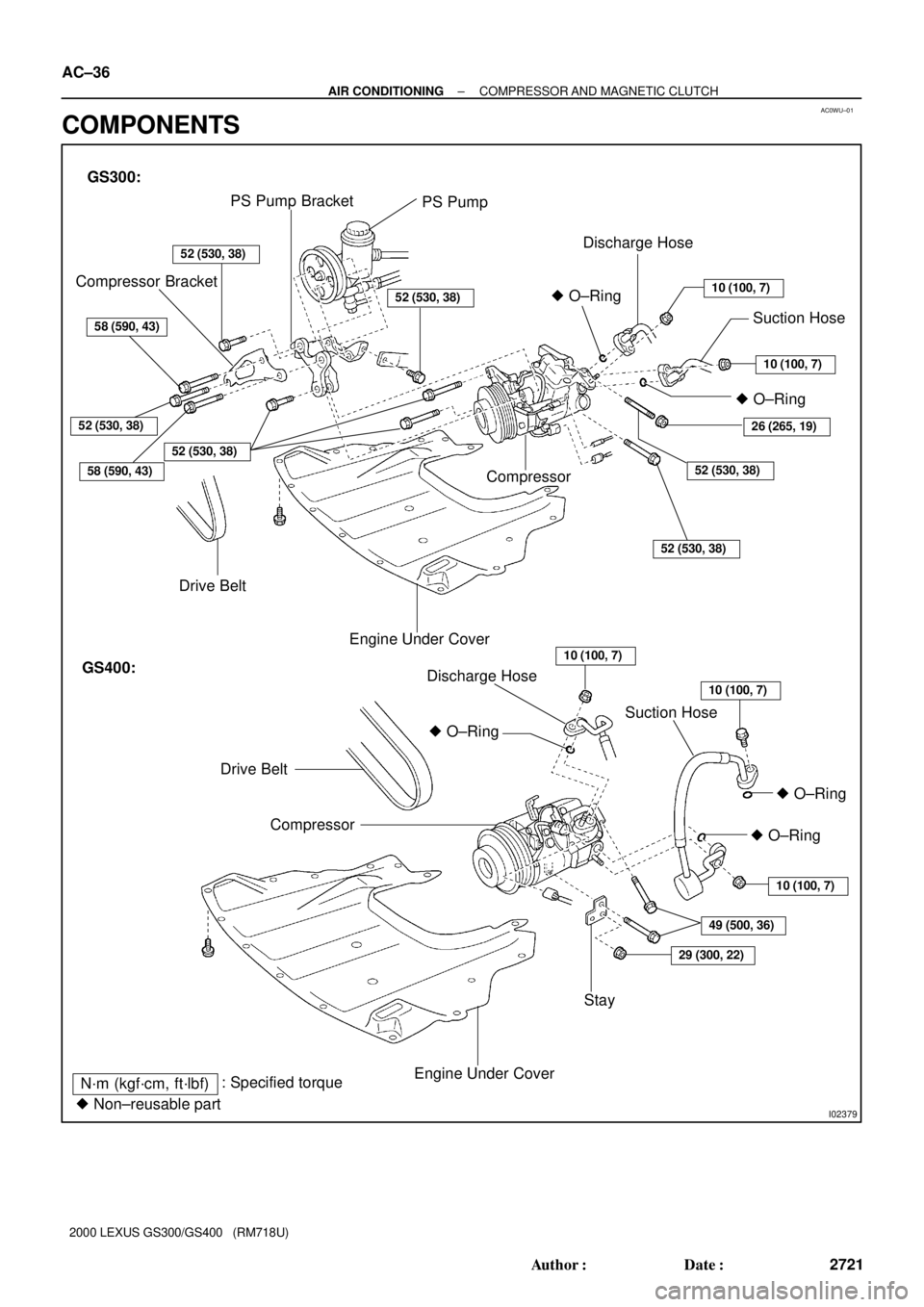
GS300:
PS Pump PS Pump Bracket
52 (530, 38)
Compressor Bracket
52 (530, 38)
58 (590, 43)
Drive Belt
52 (530, 38)� O±Ring
Discharge Hose
10 (100, 7)
Suction Hose
10 (100, 7)
� O±Ring
26 (265, 19)
52 (530, 38)
52 (530, 38)
Engine Under Cover
GS400:
Drive Belt
10 (100, 7)
10 (100, 7)Discharge Hose
Suction Hose
� O±Ring
� O±Ring
� O±Ring
10 (100, 7)
49 (500, 36)
29 (300, 22)
Stay
Engine Under Cover
Compressor
N´m (kgf´cm, ft´lbf): Specified torque
� Non±reusable part
58 (590, 43)
Compressor
52 (530, 38)
AC±36
± AIR CONDITIONINGCOMPRESSOR AND MAGNETIC CLUTCH
2721 Author�: Date�:
2000 LEXUS GS300/GS400 (RM718U)
COMPONENTS
Page 38 of 1111
AC0WV±01
I02381
I02380
I02382
AC±38
± AIR CONDITIONINGCOMPRESSOR AND MAGNETIC CLUTCH
2723 Author�: Date�:
2000 LEXUS GS300/GS400 (RM718U)
REMOVAL
1. RUN ENGINE AT IDLE SPEED WITH A/C ON FOR
APPROX. 10 MINUTES
2. STOP ENGINE
3. DISCONNECT NEGATIVE (±) TERMINAL CABLE
FROM BATTERY
4. DISCHARGE REFRIGERANT FROM REFRIGERATION
SYSTEM
5. REMOVE ENGINE UNDER COVER
6. REMOVE DRIVE BELT
(See page AC±15)
7. GS400:
DISCONNECT DISCHARGE HOSE
Remove the nut and disconnect the discharge hose.
NOTICE:
Cap the open fitting immediately to keep moisture or dirt
out of the system.
8. GS400:
REMOVE SUCTION HOSE
Remove the nut, bolt and suction hose.
NOTICE:
Cap the open fitting immediately to keep moisture or dirt
out of the system.
9. GS300:
DISCONNECT DISCHARGE AND SUCTION HOSES
Remove the 2 nut and disconnect the both hoses.
NOTICE:
Cap the open fitting immediately to keep moisture or dirt
out of the system.
Page 45 of 1111
± AIR CONDITIONINGCOMPRESSOR AND MAGNETIC CLUTCH
AC±45
2730 Author�: Date�:
2000 LEXUS GS300/GS400 (RM718U)
6. GS400:
INSTALL SUCTION HOSE
Install the suction hose with the bolt and nut.
Torque: 10 N´m (100 kgf´cm, 7 ft´lbf)
NOTICE:
Hose should be connected immediately after the caps have been removed.
HINT:
Lubricate 2 new O±rings with compressor oil and install them to the hose.
7. INSTALL DRIVE BELT
(See page AC±16)
8. INSPECT DRIVE BELT TENSION
(See page AC±14)
9. INSTALL ENGINE UNDER COVER
10. CONNECT NEGATIVE (±) TERMINAL CABLE TO BATTER
11. EVACUATE AIR FROM REFRIGERATION SYSTEM AND CHARGE SYSTEM WITH REFRIGERANT
Specified amount: 600 ± 50 g (21.16 ± 1.76 oz.)
12. INSPECT FOR LEAKAGE OF REFRIGERANT
Using a gas leak detector, check for leakage of refrigerant.
If there is leakage, check the tightening torque at the joints.
13. INSPECT A/C OPERATION
Page 139 of 1111
 (d)
Slowly
RetractedRetracted
More Quickly
I04111
Wire Harness Side
± BODY ELECTRICALELECTRIC TENSION REDUCER SYSTEM
BE±105
2406 Author�: Date�:
2000 LEXUS GS300/GS400 (RM718U")
BE0GV±04
I04110
(b) (d)
Slowly
RetractedRetracted
More Quickly
I04111
Wire Harness Side
± BODY ELECTRICALELECTRIC TENSION REDUCER SYSTEM
BE±105
2406 Author�: Date�:
2000 LEXUS GS300/GS400 (RM718U)
INSPECTION
1. INSPECT TENSION REDUCER SOLENOID OPERA-
TION
(a) Connect the positive (+) lead from the battery to terminal
1, and negative (±) lead to terminal 2.
(b) Pull the belt upward and check that the belt is slowly re-
tracted when released.
(c) Disconnect the lead from the battery.
(d) Pull the belt upward and check that the belt is retracted
more quickly when released than in (b).
HINT:
Do not tilt the retractor.
If the operation is not as specified, replace the front seat outer
belt assembly.
2. INSPECT TENSION REDUCER SOLENOID CIRCUIT
Disconnect the tension reducer solenoid connector and inspect
the connector on wire harness side, as shown.
Tester connectionConditionSpecified condition
2 ± GroundBuckle switch position
OFF (belt unfastened)No continuity
2 ± GroundBuckle switch position
ON (belt fastened)Continuity
1 ± GroundIgnition switch ACC or LOCKNo voltage
1 ± GroundIgnition switch ONBattery positive voltage
If the circuit is specified, replace the front seat outer belt assem-
bly.
If the circuit is not as specified, inspect the circuits connected
to other parts.
Page 140 of 1111
I04107
12
4
OFF
ON
I04108
Wire Harness Side BE±106
± BODY ELECTRICALELECTRIC TENSION REDUCER SYSTEM
2407 Author�: Date�:
2000 LEXUS GS300/GS400 (RM718U)
3. INSPECT SEAT BELT BUCKLE SWITCH CONTINUITY
(a) Check that continuity exists between the terminals 1 and
4 on the switch side connector with the switch ON (belt
fastened).
(b) Check that continuity exists between the terminals 2 and
4 on the switch side connector with the switch OFF (belt
unfastened).
If operation is not as specified, replace the switch.
4. INSPECT SEAT BELT BUCKLE SWITCH CIRCUIT
Driver side: (See page DI±830)
Passenger side: (See page DI±785)
Disconnect the switch connector and inspect the connector on
wire harness side, as shown.
Tester connectionConditionSpecified condition
4 ± GroundConstantContinuity
If continuity is not as specified, inspect the circuits connected
to other parts.