Page 121 of 1111
D01012
SST
Q08511
SST
D01009
D01008
AT±4
± AUTOMATIC TRANSMISSIONEXTENSION HOUSING OIL SEAL
1952 Author�: Date�:
2000 LEXUS GS300/GS400 (RM718U)
6. INSTALL EXTENSION HOUSING REAR OIL SEAL
(a) Coat the lip of a new oil seal with MP grease.
(b) Using SST and a hammer, drive in the oil seal with the lip
facing downward.
SST 09309±37010
Oil seal depth from flat end: 2.0 mm (0.079 in.)
7. INSTALL TRANSMISSION OUTPUT FLANGE
(a) Using SST and a hammer, drive in a new oil seal.
SST 09950±60010 (09951±00350), 09950±70010
(09951±07100)
(b) Install the output flange.
(c) Using a 30 mm deeper socket wrench, install and torque
a new nut.
Torque: 126 N´m (1,280 kgf´cm, 93 ft´lbf)
HINT:
Shift the shift lever to P position.
(d) Using a chisel and hammer, stake the nut.
8. INSTALL PROPELLER SHAFT
(See page PR±10)
9. INSTALL FRONT EXHAUST PIPE AND HEAT INSULA-
TOR
1UZ±FE Engine: (See page EM±120)
2JZ±GE Engine: (See page EM±97)
10. FILL AND CHECK FLUID LEVEL
(See page DI±318)
Page 122 of 1111
AT069±01
Q03794
AT±32
± AUTOMATIC TRANSMISSIONAUTOMATIC TRANSMISSION UNIT (2JZ±GE)
1980 Author�: Date�:
2000 LEXUS GS300/GS400 (RM718U)
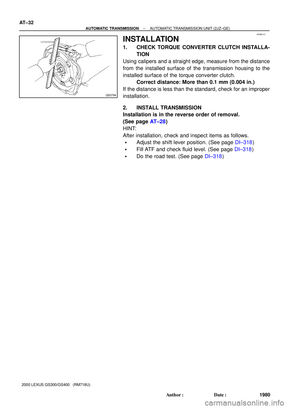
INSTALLATION
1. CHECK TORQUE CONVERTER CLUTCH INSTALLA-
TION
Using calipers and a straight edge, measure from the distance
from the installed surface of the transmission housing to the
installed surface of the torque converter clutch.
Correct distance: More than 0.1 mm (0.004 in.)
If the distance is less than the standard, check for an improper
installation.
2. INSTALL TRANSMISSION
Installation is in the reverse order of removal.
(See page AT±28)
HINT:
After installation, check and inspect items as follows.
�Adjust the shift lever position. (See page DI±318)
�Fill ATF and check fluid level. (See page DI±318)
�Do the road test. (See page DI±318)
Page 128 of 1111
AT06C±01
D01007
AT±38
± AUTOMATIC TRANSMISSIONAUTOMATIC TRANSMISSION UNIT (1UZ±FE)
1986 Author�: Date�:
2000 LEXUS GS300/GS400 (RM718U)
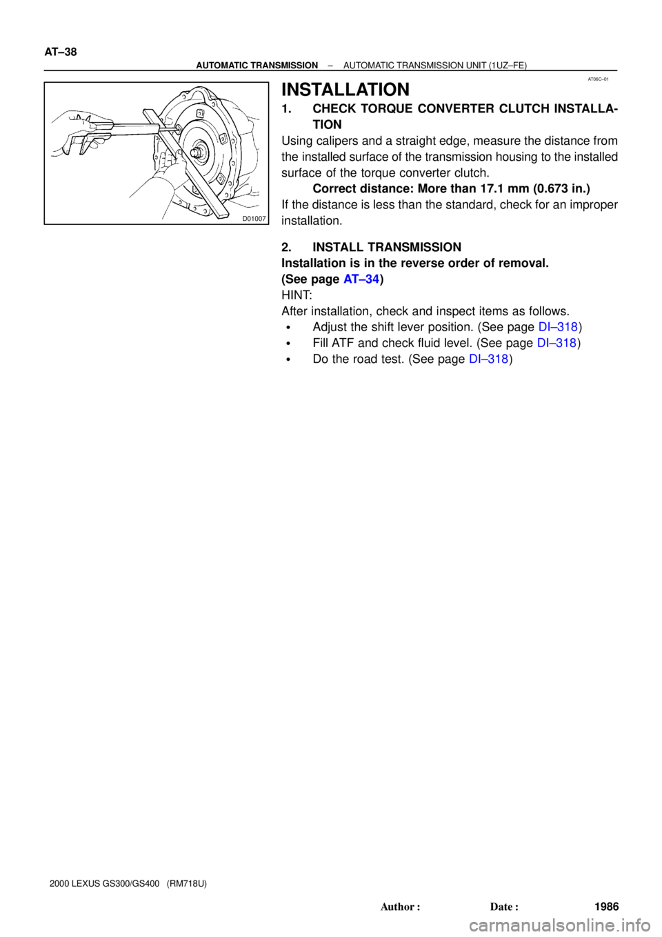
INSTALLATION
1. CHECK TORQUE CONVERTER CLUTCH INSTALLA-
TION
Using calipers and a straight edge, measure the distance from
the installed surface of the transmission housing to the installed
surface of the torque converter clutch.
Correct distance: More than 17.1 mm (0.673 in.)
If the distance is less than the standard, check for an improper
installation.
2. INSTALL TRANSMISSION
Installation is in the reverse order of removal.
(See page AT±34)
HINT:
After installation, check and inspect items as follows.
�Adjust the shift lever position. (See page DI±318)
�Fill ATF and check fluid level. (See page DI±318)
�Do the road test. (See page DI±318)
Page 130 of 1111

ATF TEMPERATURE SENSOR
ON±VEHICLE REPAIR
CAUTION:
When")
AT05Y±01
D00910
Q07487
SST
AT0103
± AUTOMATIC TRANSMISSIONATF TEMPERATURE SENSOR
AT±5
1953 Author�: Date�:
2000 LEXUS GS300/GS400 (RM718U)
ATF TEMPERATURE SENSOR
ON±VEHICLE REPAIR
CAUTION:
When working with FIPG material, you must observe the follow-
ing items.
�Using a razor blade and gasket scraper, remove all the old
FIPG material from the gasket surfaces.
�Thoroughly clean all components to remove all the loose
material.
�Clean both sealing surfaces with a non±residue solvent.
�Apply FIPG in an approx. 1 mm (0.04 in.) wide bead along
the sealing surface.
�Parts must be assembled within 10 minutes of application.
Otherwise, the FIPG material must be removed and reap-
plied.
1. REMOVE DRAIN PLUG WITH GASKET AND DRAIN
AT F
2. REMOVE OIL PAN
NOTICE:
Some fluid will remain in the oil pan.
(a) Remove the 19 bolts.
(b) Install the blade of SST between the transmission case
and oil pan, cut off applied sealer, and remove the oil pan.
SST 09032±00100
NOTICE:
When removing the oil pan, be careful not to damage the oil
pan flange.
3. EXAMINE PARTICLES IN PAN
Remove the magnets and use them to collect steel particles.
Carefully look at the foreign matter and particles in the pan and
on the magnets to anticipate the type of wear you will find in the
transmission.
Steel (magnetic) ... bearing, gear and clutch plate wear
Brass (non±magnetic) ... bushing wear
Page 131 of 1111
D00752
D00753
D00909
D00916
D00909
AT±6
± AUTOMATIC TRANSMISSIONATF TEMPERATURE SENSOR
1954 Author�: Date�:
2000 LEXUS GS300/GS400 (RM718U)
4. REMOVE OIL STRAINER
NOTICE:
Be careful as some fluid will come out of the oil strainer.
(a) Remove the 4 bolts and oil strainer.
(b) Remove the 3 gaskets from the oil strainer.
5. REMOVE SOLENOID WIRING WITH ATF TEMPERA-
TURE SENSOR
(a) Disconnect the ATF temperature sensor.
(b) Remove the bolt and clamp.
(c) Disconnect the 7 connectors from the solenoid valves.
(d) Remove the bolt and pull out the solenoid connector.
6. INSTALL SOLENOID WIRING WITH ATF TEMPERA-
TURE SENSOR
(a) Install the solenoid connector with the bolt.
Torque: 5.4 N´m (55 kgf´cm, 48 in.´lbf)
(b) Connect the 7 connectors to the solenoid valves.
(c) Install the clamp with the bolt.
Torque: 6.4 N´m (65 kgf´cm, 56 in.´lbf)
(d) Connect the ATF temperature sensor.
Page 132 of 1111
D00753
D00752
D00912
D01917
Seal Breadth 2 ~ 3 mm (0.08 ~ 0.12 in.)
D00910
ºAº
± AUTOMATIC TRANSMISSIONATF TEMPERATURE SENSOR
AT±7
1955 Author�: Date�:
2000 LEXUS GS300/GS400 (RM718U)
7. INSTALL OIL STRAINER
(a) Install 3 new gaskets.
(b) Install the oil strainer with the 4 bolts.
Torque: 10 N´m (100 kgf´cm, 7 ft´lbf)
8. INSTALL OIL PAN
(a) Install the 3 magnets in the indications of the oil pan.
(b) Remove any packing material and be careful not to drop
oil on the contacting surfaces of the transmission case
and oil pan.
(c) Apply FIPG to the oil pan.
FIPG:
Part No. 08826 ± 00090, THREE BOND 1281 or
equivalent
(d) Install the oil pan with the 19 bolts.
Torque: 7.4 N´m (75 kgf´cm, 65 in.´lbf)
HINT:
Replace the only ºAº bolt with a new one.
9. INSTALL DRAIN PLUG WITH NEW GASKET
Torque: 20 N´m (205 kgf´cm, 15 ft´lbf)
10. FILL FLUID AND CHECK FLUID
(See page DI±318)
Page 135 of 1111
D00754
A
CB
B
B
B
C
CA
DB
AT±10
± AUTOMATIC TRANSMISSIONVALVE BODY ASSEMBLY
1958 Author�: Date�:
2000 LEXUS GS300/GS400 (RM718U)
(b) Install the 21 bolts.
Torque: 10 N´m (100 kgf´cm, 7 ft´lbf)
Bolt length:
Bolt A: 23 mm (0.91 in.)
Bolt B: 28 mm (1.10 in.)
Bolt C: 36 mm (1.42 in.)
Bolt D: 55 mm (2.17 in.)
12. INSTALL SOLENOID WIRING WITH ATF TEMPERA-
TURE SENSOR (See page AT±5)
13. INSTALL OIL STRAINER (See page AT±5)
14. INSTALL OIL PAN (See page AT±5)
15. INSTALL DRAIN PLUG WITH NEW GASKET
Torque: 20 N´m (205 kgf´cm, 15 ft´lbf)
16. FILL FLUID AND CHECK FLUID (See page DI±318)
Page 639 of 1111

TERMS
ABBREVIATIONS USED IN THIS MANUAL
AbbreviationsMeaning
ABSAnti±Lock Brake System
ACAlternating Current")
IN04Q±07
IN±36
± INTRODUCTIONTERMS
36 Author�: Date�:
2000 LEXUS GS300/GS400 (RM718U)
TERMS
ABBREVIATIONS USED IN THIS MANUAL
AbbreviationsMeaning
ABSAnti±Lock Brake System
ACAlternating Current
ACCAccessory
ACISAcoustic Control Induction System
ACSDAutomatic Cold Start Device
A.D.D.Automatic Disconnecting Differential
A/FAir±Fuel Ratio
AHCActive Height Control Suspension
ALRAutomatic Locking Retractor
ALTAlternator
AMPAmplifier
ANTAntenna
APPROX.Approximately
A/TAutomatic Transmission (Transaxle)
AT FAutomatic Transmission Fluid
AUTOAutomatic
AUXAuxiliary
AV GAverage
AV SAdaptive Variable Suspension
BABrake Assist
BACSBoost Altitude Compensation System
BATBattery
BDCBottom Dead Center
B/LBi±Level
B/SBore±Stroke Ratio
BTDCBefore Top Dead Center
BVSVBimetallic Vacuum Switching Valve
Calif.California
CBCircuit Breaker
CCoCatalytic Converter For Oxidation
CDCompact Disc
CFCornering Force
CGCenter Of Gravity
CHChannel
COMB.Combination
CPECoupe
CPSCombustion Pressure Sensor
CPUCentral Processing Unit
CRSChild Restraint System
CTRCenter
C/VCheck Valve
CVControl Valve