Page 487 of 1111
B01985
Water Bypass Outlet
� O±Ring
Engine Wire
Water
Pump
Connector Bracket
Idler PulleyGasket
Timing Belt GuideNo.2 Water Bypass Pipe
Drain Hose
Timing Belt Tensioner
Timing Belt
Drive Belt TensionerOil Filler Cap
No.3 Timing Belt Cover
No.1 Water
Bypass Pipe
� Gasket
Crankshaft PulleyDust Boot
x 5 Thermostat
� O±Ring
� O±Ring
No.2 Timing Belt Cover
Gasket
No.1 Timing Belt Cover
� Gasket
Water Inlet
x 6
35 (350, 26)
21 (210, 15)
21 (210, 15)
27 (270, 20)�
N´m (kgf´cm, ft´lbf) : Specified torque
� Non±reusable part
� Precoated part
330 (3,300, 243)
Clamp Bracket
Crankshaft Position
Sensor Connector
Gasket
CO±4
± COOLING (2JZ±GE)WATER PUMP
1542 Author�: Date�:
2000 LEXUS GS300/GS400 (RM718U)
Page 493 of 1111
WATER PUMP
CO±5
1543 Author�: Dat")
CO09Z±03
A02725Turn
Loosen
B01614
Water Bypass Outlet
No.1 Water Bypass Hose
B01638
Clamp Bracket
Connector Bracket
B01572No.2 Water Bypass Pipe
± COOLING (2JZ±GE)WATER PUMP
CO±5
1543 Author�: Date�:
2000 LEXUS GS300/GS400 (RM718U)
REMOVAL
1. REMOVE RADIATOR ASSEMBLY
(See page CO±18)
2. REMOVE DRIVE BELT AND WATER PUMP PULLEY
(a) Loosen the 4 nuts holding the water pump pulley to the
water pump.
(b) Loosen the drive belt tension by turning the drive belt ten-
sioner clockwise, and remove the drive belt.
(c) Remove the 4 nuts and water pump pulley.
3. REMOVE TIMING BELT AND IDLER PULLEY
(See page EM±16)
4. REMOVE WATER BYPASS OUTLET AND NO.1
WATER BYPASS PIPE
(a) Remove the 2 bolts, water bypass outlet and No.1 water
bypass pipe.
(b) Remove the 3 O±rings from the water bypass outlet and
No.1 water bypass pipe.
5. REMOVE WATER INLET AND THERMOSTAT
(See page CO±11)
6. REMOVE WATER PUMP
(a) Loosen the nut and remove the bolt, slide the generator
away from the water pump.
(b) Remove the bolt, and disconnect the clamp bracket (for
engine wire).
(c) Remove the bolt, and disconnect the connector bracket
(for crankshaft position sensor connector).
(d) Remove the 2 nuts, and disconnect the No.2 water by-
pass pipe from the water pump.
Page 496 of 1111
WATER PUMP
1546 Author�: Date�:
2000 LEXUS GS300/GS400 (RM718U)
INSTALLATION
1. INST")
CO0A1±03
P03945
New
O±Ring
P02574
New Gasket
A02801
AB A
B
A
B
B
B
B01614
New O±Ring
CO±8
± COOLING (2JZ±GE)WATER PUMP
1546 Author�: Date�:
2000 LEXUS GS300/GS400 (RM718U)
INSTALLATION
1. INSTALL WATER PUMP
(a) Install a new O±ring to the cylinder block.
(b) Install the drain hose.
(c) Install a new gasket to the water pump.
(d) Connect the water pump to the water bypass pipe. Do not
install the nut yet.
(e) Install the water pump with the 2 bolts (A) and 4 bolts (B).
Torque: 21 N´m (210 kgf´cm, 15 ft´lbf)
HINT:
Hand tighten the (A) bolts first.
(f) Install the 2 nuts holding the No.2 water bypass pipe to
the water pump.
Torque: 21 N´m (210 kgf´cm, 15 ft´lbf)
(g) Install the connector bracket (for crankshaft position sen-
sor connector) with the bolt.
(h) Install the clamp bracket (for engine wire) with the bolt.
(i) Install the generator with the bolt and nut.
Torque: 40 N´m (400 kgf´cm, 30 ft´lbf)
2. INSTALL THERMOSTAT AND WATER INLET
(See page CO±13)
3. INSTALL NO.1 WATER BYPASS PIPE AND WATER
BYPASS OUTLET
(a) Install 2 new O±rings to the No.1 water bypass pipe.
(b) Install a new O±ring and the water bypass outlet with the
2 bolts.
Torque: 9.0 N´m (90 kgf´cm, 80 in.´lbf)
4. INSTALL IDLER PULLEY AND TIMING BELT
(See page EM±23)
5. INSTALL WATER PUMP PULLEY AND DRIVE BELT
Torque: 14 N´m (140 kgf´cm, 10 ft´lbf)
Page 518 of 1111

A11128
Accelerator Pedal Position Sensor Connector
Throttle Control Motor Connector
Throttle Body and Intake Air Connector Assembly
Water Bypass HoseVSV Connector
for EVAP
EVAP Hose
� Gasket Air Assist Hose Engine Wire
Oil Filler Cap
No.3 Timing Belt Cover
Gasket
No.2 Timing Belt Cover
GasketThrottle
Position
Sensor
Connector
Vacuum Hose
(from Actuator for ACIS)
Water Bypass Hose
Engine Wire Protector
High±Tension
Cord w/ Clamp
No.1 Cylinder
Head Cover
Gasket
Timing Belt
x 6
Timing Belt Guide
Gasket
x 5 No.1 Timing Belt Cover
Crankshaft
Pulley
21 (210, 15)
Drive Belt Tensioner
330 (3,300, 243)
Camshaft
Timing Pulley
(VVT±i Pulley)81 (810, 60)
Straight
Screw Plug
15 (150, 11)Seal Washer
Camshaft
Timing Oil
Control Valve
Camshaft Timing
Oil Control
Valve Connector� Gasket
Oil Control Valve Filter
� O±Ring
No.1 Oil PipeUnion Bolt
55 (550, 41)
Idler Pulley
Crankshaft Timing Pulley
Timing Belt Plate
Timing Belt Tensioner
N´m (kgf´cm, ft´lbf) : Specified torque
35 (350, 26)�
8.0 (80, 71 in.´lbf)
27 (270, 20)
� Non±reusable part
� Precoated part
Dust Boot
Engine Wire ClampPCV Hose
Vacuum Hose
(from No.2
Vacuum Pipe)
± ENGINE MECHANICAL (2JZ±GE)TIMING BELT
EM±15
1369 Author�: Date�:
2000 LEXUS GS300/GS400 (RM718U)
Page 533 of 1111
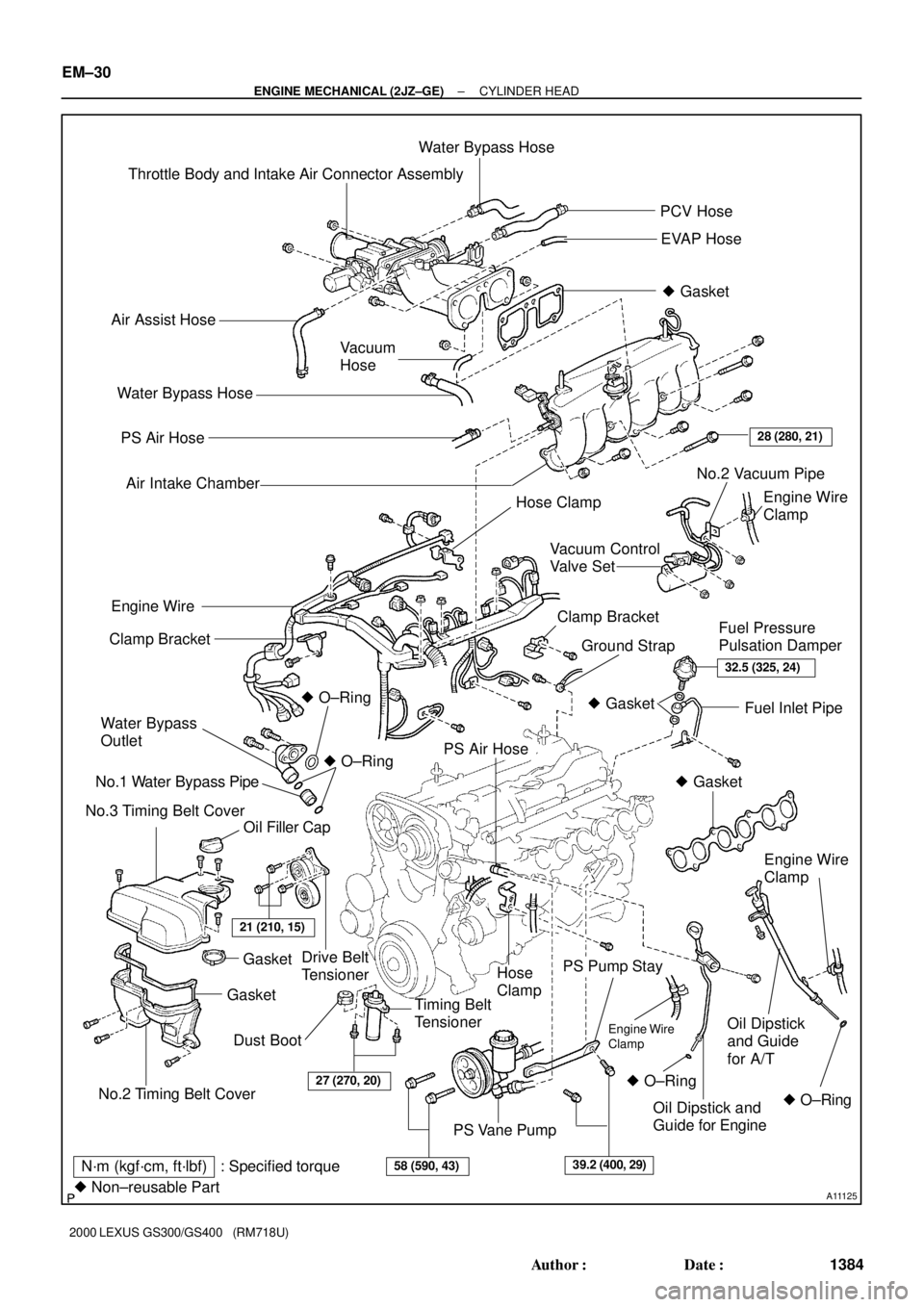
A11125
Throttle Body and Intake Air Connector AssemblyWater Bypass Hose
PCV Hose
EVAP Hose
� Gasket
Air Assist Hose
Vacuum
Hose
PS Air Hose
Air Intake Chamber
Engine Wire
Clamp
Drive Belt
TensionerClamp Bracket
Ground StrapFuel Pressure
Pulsation Damper Clamp Bracket
Water Bypass
Outlet
No.1 Water Bypass Pipe
No.3 Timing Belt Cover� O±Ring
Oil Filler CapFuel Inlet Pipe
PS Air Hose
Hose
Clamp
Timing Belt
Tensioner
PS Pump Stay
Oil Dipstick
and Guide
for A/T
PS Vane Pump Water Bypass Hose
28 (280, 21)
Engine Wire
� O±Ring
No.2 Timing Belt Cover
GasketGasket
21 (210, 15)
32.5 (325, 24)
� Gasket
� Gasket
Engine Wire
Clamp
� O±Ring � O±RingOil Dipstick and
Guide for Engine
27 (270, 20)
58 (590, 43)39.2 (400, 29)N´m (kgf´cm, ft´lbf) : Specified torque
� Non±reusable Part
Dust BootEngine Wire
Clamp
No.2 Vacuum Pipe
Hose Clamp
Vacuum Control
Valve Set
EM±30
± ENGINE MECHANICAL (2JZ±GE)CYLINDER HEAD
1384 Author�: Date�:
2000 LEXUS GS300/GS400 (RM718U)
Page 535 of 1111
A02822
� Oil Seal
� Non±reusable part
� Precoated part
�
� Gasket� Gasket
ECT Sensor
� Valve Guide Bushing
Valve
Water Outlet with Water Bypass Hose
Camshaft Position SensorEngine Hanger Heater Union
Cylinder HeadSpring Seat Valve Spring Spring RetainerKeeper
Adjusting Shim
Valve Lifter
EM±32
± ENGINE MECHANICAL (2JZ±GE)CYLINDER HEAD
1386 Author�: Date�:
2000 LEXUS GS300/GS400 (RM718U)
Page 539 of 1111
CYLINDER HEAD
1388 Author�: Date�:
2000 LEXUS GS300/GS400 (RM718U)
(b) Remove the 3 bolts and nuts holding the front exhaust
pipe to the exh")
A02819
A09752
A02735
EM±34
± ENGINE MECHANICAL (2JZ±GE)CYLINDER HEAD
1388 Author�: Date�:
2000 LEXUS GS300/GS400 (RM718U)
(b) Remove the 3 bolts and nuts holding the front exhaust
pipe to the exhaust manifold.
(c) Remove the 2 bolts and pipe support bracket.
(d) Disconnect the front exhaust pipe from the exhaust man-
ifold, and remove the 2 gaskets.
10. REMOVE EXHAUST MANIFOLD
(a) Disconnect the 3 heated oxygen sensor connectors and
clamp.
(b) Remove the clamp and case clamp.
(c) Using a 14 mm deep socket wrench, remove the 8 nuts,
exhaust manifold and 2 gaskets.
11. REMOVE WATER BYPASS OUTLET AND NO.1
WATER BYPASS PIPE (See page CO±11)
12. REMOVE THROTTLE BODY AND INTAKE AIR
CONNECTOR ASSEMBLY (See page EM±5)
13. REMOVE OIL DIPSTICK AND GUIDE FOR ENGINE
(See page LU±6)
14. REMOVE OIL DIPSTICK AND GUIDE FOR A/T
(See page EM±62)
15. REMOVE AIR INTAKE CHAMBER (See page SF±46)
16. REMOVE VACUUM CONTROL VALVE SET AND NO.2
VACUUM PIPE
(a) Disconnect the VSV connector for the ACIS.
(b) Remove the 3 nuts, vacuum control valve set and No.2
vacuum pipe.
(c) Disconnect the engine wire clamp from the clamp bracket
of the No.2 vacuum pipe.
17. REMOVE NO.3 TIMING BELT COVER
18. REMOVE IGNITION COILS AND HIGH±TENSION
CORD SET ASSEMBLY (See page IG±7)
19. REMOVE SPARK PLUGS
Page 540 of 1111

(b) (c)
(d)(d)
(c) (b)
A02811
A02733
Clamp Bracket
A11123
5 mm
Hexagon
Wrench
± ENGINE MECHANICAL (2JZ±GE)CYLINDER HEAD
EM±35
1389 Author�: Date�:
2000 LEXUS GS300/GS400 (RM718U)
20. D")
A02732
(a)
(b) (c)
(d)(d)
(c) (b)
A02811
A02733
Clamp Bracket
A11123
5 mm
Hexagon
Wrench
± ENGINE MECHANICAL (2JZ±GE)CYLINDER HEAD
EM±35
1389 Author�: Date�:
2000 LEXUS GS300/GS400 (RM718U)
20. DISCONNECT ENGINE WIRE FROM CYLINDER HEAD
(a) Disconnect the ground strap from the cylinder head.
(b) Disconnect the 2 water bypass hoses from the hose
clamps on the cylinder head and oil filter bracket.
(c) Remove the 2 bolts and hose clamps.
(d) Disconnect the heated oxygen sensor (bank 2 sensor 1)
connector and engine wire clamp from the hose clamps.
(e) Disconnect the heated oxygen sensor (bank 1 sensor 1)
connector.
(f) Disconnect the crankshaft position sensor connector.
(g) Disconnect the generator connector.
(h) Remove the bolt and clamp bracket, and disconnect the
engine wire from the water pump.
(i) Disconnect the 2 ground terminals from the intake man-
ifold.
(j) Disconnect the 2 engine wire clamps from the No.1 oil
pipe and clamp bracket on the intake manifold.
(k) Remove the bolt and clamp bracket.
(l) Disconnect the ECT sensor connector.
(m) Remove the 2 knock sensor connectors.
(n) Remove the oil pressure switch connector.
(o) Remove the oil level sensor connector.
(p) Remove the starter connector.
(q) Remove the 6 injector connectors.
(r) Remove the camshaft timing oil control valve connector.
(s) Remove the camshaft position sensor connector.
(t) Using a 5 mm hexagon wrench, remove the bolt holding
the engine wire protector to the No.2 cylinder head cover.
(u) Remove the 3 nuts, and disconnect the engine wire pro-
tector from the intake manifold.
21. REMOVE FUEL PRESSURE PULSATION DAMPER
(See page SF±26)