Page 115 of 1111

AT067±01
D01040
� Gasket
Clamp
ClampAir Cleaner, MAF Meter and Intake
Air Connector Pipe Assembly
Exhaust Manifold with TWC
Connector and
Wire Harness Level Gauge
Filler PipeAdjusting WasherPropeller Shaft Assembly
Shift Control Rod
Torque Converter ClutchPlug for Line
Pressure TestHeat Insulator
Heated Oxygen Sensor
Front and Center
Exhaust PipeFront Floor
Center Brace
Engine Under Cover Pipe Support BracketO±Ring Heat Insulator
� Gasket� Starterx6x839 (400, 29)
44 (450, 33)
72 (730, 53)
37 (380, 27)
13 (130, 9)
79 (805, 58)
37 (375, 27)
7.4 (75, 65 in.´lbf)
44 (450, 33)
44 (450, 33)
37 (380, 27)
37 (380, 27)
Hole Plug
5.4 (55, 48 in.´lbf)
Oil Cooler Pipe
x5
� O±Ring
5.4 (55, 48 in.´lbf)
� Gasket
44 (450, 33)
�
5.4 (55, 48 in.´lbf)
N´m (kgf´cm,ft´lbf) : Specified torque
� Non±reusable part� Gasket
48 (490, 35)
26 (270, 20)
44 (450, 33)
44 (450, 33)
�
79 (805, 58)
± AUTOMATIC TRANSMISSIONAUTOMATIC TRANSMISSION UNIT (2JZ±GE)
AT±27
1975 Author�: Date�:
2000 LEXUS GS300/GS400 (RM718U)
AUTOMATIC TRANSMISSION UNIT (2JZ±GE)
COMPONENTS
Page 121 of 1111
D01012
SST
Q08511
SST
D01009
D01008
AT±4
± AUTOMATIC TRANSMISSIONEXTENSION HOUSING OIL SEAL
1952 Author�: Date�:
2000 LEXUS GS300/GS400 (RM718U)
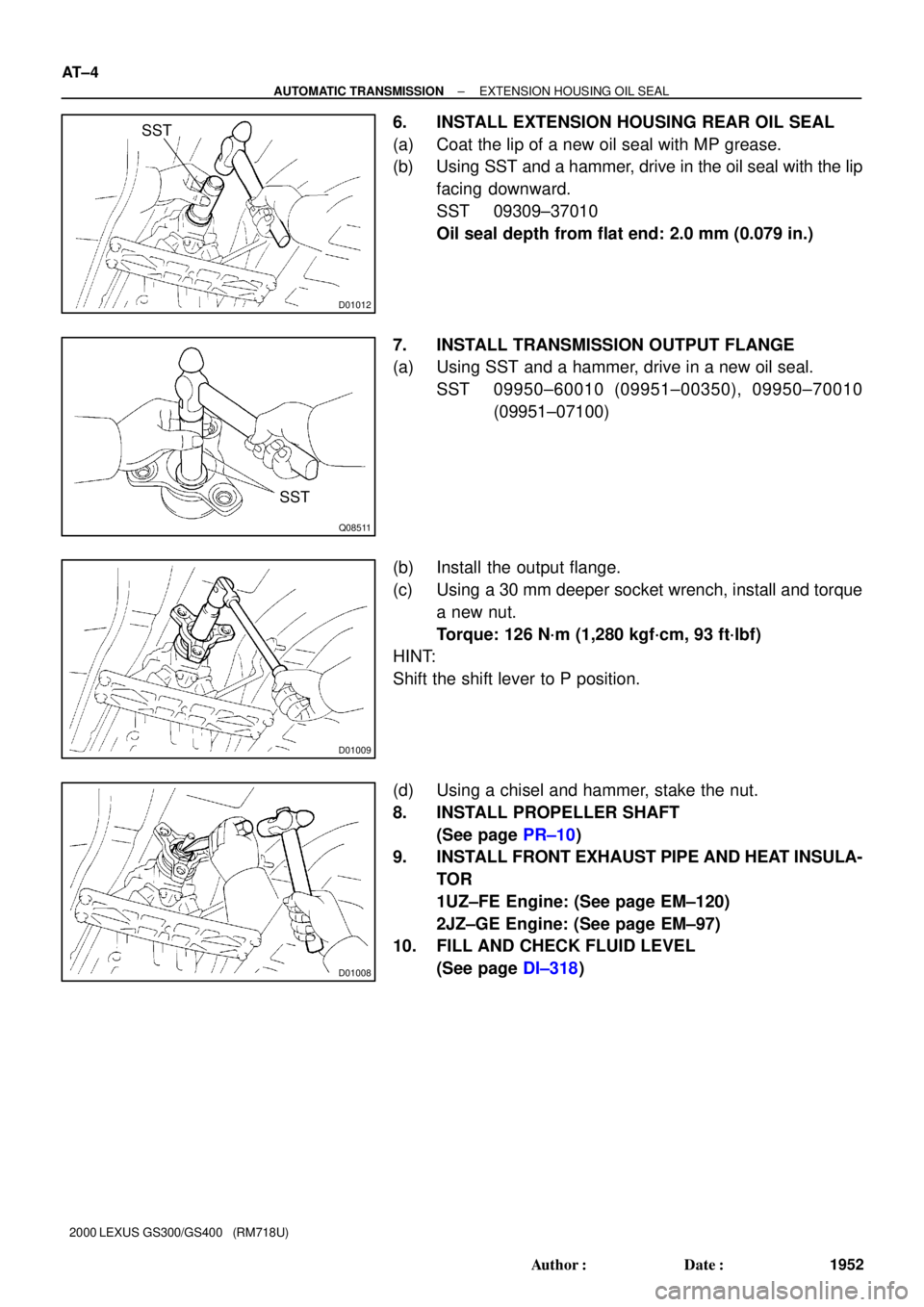
6. INSTALL EXTENSION HOUSING REAR OIL SEAL
(a) Coat the lip of a new oil seal with MP grease.
(b) Using SST and a hammer, drive in the oil seal with the lip
facing downward.
SST 09309±37010
Oil seal depth from flat end: 2.0 mm (0.079 in.)
7. INSTALL TRANSMISSION OUTPUT FLANGE
(a) Using SST and a hammer, drive in a new oil seal.
SST 09950±60010 (09951±00350), 09950±70010
(09951±07100)
(b) Install the output flange.
(c) Using a 30 mm deeper socket wrench, install and torque
a new nut.
Torque: 126 N´m (1,280 kgf´cm, 93 ft´lbf)
HINT:
Shift the shift lever to P position.
(d) Using a chisel and hammer, stake the nut.
8. INSTALL PROPELLER SHAFT
(See page PR±10)
9. INSTALL FRONT EXHAUST PIPE AND HEAT INSULA-
TOR
1UZ±FE Engine: (See page EM±120)
2JZ±GE Engine: (See page EM±97)
10. FILL AND CHECK FLUID LEVEL
(See page DI±318)
Page 123 of 1111

AT06A±01
D01049
Oil Cooler Pipe
Connector and Wire Harness
Level Gauge
Torque Converter Clutch
Flywheel Housing
Under CoverPlug for Line
Pressure Test
Front and Center Exhaust PipePropeller Shaft Assembly
Heated Oxygen Sensor
Pipe Support BracketRH Front TWC
Engine Under CoverHeat Insulator
Ground CableHeat Insulator � GasketO±Ring x6Adjusting Washer
Filler Pipe
44 (450, 33)
79 (805, 58)
37 (375, 27)
79 (805, 58)
13 (130, 9)
37 (380, 27)
18 (185, 13)
44 (450, 33)
44 (450, 33)
62 (630, 46)
62 (630, 46)
72 (730, 53)
37 (380, 27)
48 (490, 35)
44 (450, 33)44 (450, 33)
5.4 (55, 48 in.´lbf)
5.4 (55, 48 in.´lbf)
Heat Insulator
26 (270, 20)
� Gasket
LH Front TWC
44 (450, 33)
� Gasket
� Gasket
�
�� �
�
�
�
���
�
N´m (kgf´cm, ft´lbf) : Specified torque
Non±reusable part �Heat Insulator
5.4 (55, 48 in.´lbf)
44 (450, 33)
44 (450, 33)
� O±Ring
Heated Oxygen
SensorFront Floor
Center Brace
7.4 (75, 65 in.´lbf)
x6
± AUTOMATIC TRANSMISSIONAUTOMATIC TRANSMISSION UNIT (1UZ±FE)
AT±33
1981 Author�: Date�:
2000 LEXUS GS300/GS400 (RM718U)
AUTOMATIC TRANSMISSION UNIT (1UZ±FE)
COMPONENTS
Page 364 of 1111
I01360
Fuel Tank
� Fuel Main
Sender Gauge
Fuel Tank
� Fuel Sub
Sender Gauge
Occupant Detection Sensor
(Passenger seat belt
warning sensor)
Engine Oil Level
Warning Sensor Engine Oil Level
Warning Sensor
Park/ Neutral
Position Switch
Low Oil Pressure
Warning Switch
Park/ Neutral
Position Switch
Low Oil Pressure
Warning Switch
GS300GS400 Light Failure Sensor
± BODY ELECTRICALCOMBINATION METER
BE±81
2382 Author�: Date�:
2000 LEXUS GS300/GS400 (RM718U)
Page 366 of 1111
I04250
� Combination Meter Wiring Circuit ± 1
:Speedometer
:Tachometer
:Fuel Receiver Gauge
:Engine Coolant
Temperature
Receiver Gauge
Speed Control Unit
CLOCK
to GAUGE Fuse
to MPX±B Fuse
to SRS Fuse
Tilt and Telescopic ECU
Body ECU NO.2ECM (GS400)
Ignitor (GS300)
Fuel Main Sender GaugeGround
Fuel Sub Sender Gauge
Light Control Rheostat
Illuminations
ABS, TRAC and VSC ECU
ABS, TRAC and VSC ECU Speed Signal Passenger seat
belt warning
Rr LIGHTS
SEAT BELT
OIL PRESS
OIL LEVEL
DOOR IG+
SRS +BA/T P
A/T R
A/T N
A/T D
A/T 4
A/T 3
A/T 2
A/T L
CRUISE MPX+BIG+IG+
5V
+B
to ECUto
PANEL
Fuse B4
B5
B6
B9
A5
A17A3A8 B16
LCDECU S
T
F
E
Power Source
Brake
Buzzer A11A2 A1 A6
B1
B13
B14A4
B22 ECU
ECU
ECU
S
T
F
E
CHARGE
FUEL LVL
ECT PWR
ECT SNOW TAIL or HEAD
Ground IG+IG+ IG+ IG+
+B
± BODY ELECTRICALCOMBINATION METER
BE±83
2384 Author�: Date�:
2000 LEXUS GS300/GS400 (RM718U)
Page 371 of 1111

I04253
� Meter Circuit Plate ± 2
Combination Meter ECU
SLIP Indicator
TRAC OFF Indicator
Window Washer Level Warning
ABS Warning
VSC Warning
Brake Fluid Level Warning
ECT SNOW Indicator
Low Oil Pressure Warning
ECT PWR Indicator
Discharge Warning
CRUISE MAIN Indicator
Seat Belt Warning
Rear Light Indicator
Headlight Leveling Indicator
SRS Warning
Open Door Warning
Fog Light IndicatorA/T 2 Indicaor
Engine Oil Level Indicator
Malfunction Indicator
Fuel Level Indicator
Headlight Indicator (USA)
Taillight Indicator (CANADA) ODO/
TRIP
Display
PanelIG+
SLIP
TRC OFF
WASHER
ABS
VSC
BRAKE
ECT SNOW
OIL P
ECT PWR
CHARGE
CRUISE
SEAT BELT
Rr LIGHT
HEAD LVL
AIRBAG
SRS +B
DOOR
FR FOG
COM1
SEG30
TEST1
TEST2
TEST3
GroundCHECK
ENG
IG+
FUEL
IG+
BEAM±
BEAM+ SRS +BTAIL A/T R
A/T L
A/T N
A/T D
OIL LVLDIM+
A/T 2
A/T 3
A/T 4F12
A/T PF11
F10
F9
F8
F5
F4
F2
F1
C7
C5
C3
D12
D8 E11
E10
E9
E8
E7
E6
J1
J33
D6
D4Hi±Beam Indicator
D2 E20
E19
E18
E17
E16
E15
E14
E13
E12
E3
E1 E5
E4A/T 3 Indicaor
A/T 4 Indicaor
A/T P Indicaor
A/T R Indicaor
A/T L Indicaor
A/T N Indicaor
A/T D Indicaor
T1
T2
T3
T4
~~
D10 BE±88
± BODY ELECTRICALCOMBINATION METER
2389 Author�: Date�:
2000 LEXUS GS300/GS400 (RM718U)
Page 376 of 1111

I04079
Connector ºCº Connector ºDº
Connector ºFº Connector ºEº
Connector ºGº
1 131 13
1 201 12
± BODY ELECTRICALCOMBINATION METER
BE±93
2394 Author�: Date�:
2000 LEXUS GS300/GS400 (RM718U)
2. INSPECT COMBINATION METER CIRCUIT PLATE
Warning light circuit plate:
(a) Remove meter cover.
(b) Disconnect connectors ºCº, ºDº, ºEº, ºFº and ºGº from the
meter circuit plate and inspect the connectors on the wire
harness side as shown in the table.
Tester connectionCheck indicator lightSpecified condition
D10 (+) ± D12 (±)Fuel level warning lightContinuity
D6 (+) ± D8 (±)Headlight indiactor light (USA)
Taillight indiactor light (CANADA)Continuity
D2 (+) ± D4 (±)Hi±beam indicator lightContinuity
C3 (+) ± C7 (±)Engine oil level warning lightContinuity
C3 (+) ± C5 (±)Malfunction indicator lightContinuity
E19 (±) ± E20 (+)Slip warning lightContinuity
E18 (±) ± E20 (+)TRAC OFF indicator lightContinuity
E17 (±) ± E20 (+)Window washer level warning lightContinuity
E16 (±) ± E20 (+)ABS warning lightContinuity
E15 (±) ± E20 (+)VSC OFF indicator lightContinuity
E14 (±) ± E20 (+)Brake warning lightContinuity
E13 (±) ± E20 (+)ECT SNOW indicator lightContinuity
E12 (±) ± E20 (+)Low oil pressure warning lightContinuity
E11 (±) ± E20 (+)ECT PWR indicator lightContinuity
E10 (±) ± E20 (+)Discharge warning lightContinuity
E9 (±) ± E20 (+)CRUISE MAIN indicator lightContinuity
E8 (±) ± E20 (+)Seat belt warning lightContinuity
E7 (±) ± E20 (+)Rear Lights warning lightContinuity
E6 (±) ± E20 (+)Headlight leveling indiactorContinuity
E4 (+) ± E5 (±)SRS warning lightContinuity
E3 (±) ± E4 (+)Open door warning lightContinuity
F4 (±) ± F12 (+)A/T shift indicator light (L)Continuity
F11 (±) ± F12 (+)A/T shift indicator light (2)Continuity
F10 (±) ± F12 (+)A/T shift indicator light (3)Continuity
F8 (±) ± F12 (+)A/T shift indicator light (P)Continuity
Page 382 of 1111

17. INSPECT LOW OIL PRESSURE S")
I01278
I01279
Battery Ignition
SwitchWarning Light
I04095
OFF
ON
I04096
± BODY ELECTRICALCOMBINATION METER
BE±99
2400 Author�: Date�:
2000 LEXUS GS300/GS400 (RM718U)
17. INSPECT LOW OIL PRESSURE SWITCH CONTINUITY
(a) Disconnect the connector from the switch.
(b) Check that continuity exists between terminal and ground
with the engine stopped.
(c) Check that no continuity exists between terminal and
ground with the engine running.
HINT:
Oil pressure should be over 24.5 kPa (0.25 kgf/cm
2, 3.55 psi).
If operation is not as specified, replace the switch.
18. INSPECT BRAKE WARNING LIGHT
(a) Disconnect the connector from the brake fluid warning
switch.
(b) Release the parking brake pedal.
(c) Connect the terminals on the wire harness side of the lev-
el warning switch connector.
(d) Start the engine, check that the warning light lights up.
If the warning light does not light up, test the bulb or wire har-
ness.
19. INSPECT BRAKE FLUID LEVEL WARNING SWITCH
CONTINUITY
(a) Remove the reservoir tank cap and strainer.
(b) Disconnect the connector.
(c) Check that no continuity exists between the terminals with
the switch OFF (float up).
(d) Use siphon, etc. to take fluid out of the reservoir tank.
(e) Check that continuity exists between the terminals with
the switch ON (float down)
(f) Pour the fluid back in the reservoir tank.
If operation is not as specified, replace the switch.
20. INSPECT BRAKE FLUID LEVEL WARNING SWITCH
CIRCUIT (See page DI±835)
21. INSPECT PARKING BRAKE SWITCH CONTINUITY
(a) Check that continuity exists between the terminal and
switch body with the switch ON (switch pin released).
(b) Check that no continuity exists between the terminal and
switch body with the switch OFF (switch pin pushed in).
If operation is not as specified, replace the switch or inspect
ground point.
22. INSPECT PARKING BRAKE SWITCH CIRCUIT
(See page DI±796)