Page 503 of 1111
EC04V±06
B08612
PCV Valve VSV for EVAP
Front TWC
EVAP Service Port
Fill Check LineCutoff ValveCharcoal Canister
Air Inlet Line
Vapor Pressure Sensor
Fuel Tank Cap
VSV for Vapor
Pressure Sensor
Purge Line
EVAP Line
Vent Line
Air Drain Hose
Rear TWC
EC±2
± EMISSION CONTROL (2JZ±GE)PARTS LAYOUT AND SCHEMATIC DRAWING
1453 Author�: Date�:
2000 LEXUS GS300/GS400 (RM718U)
PARTS LAYOUT AND SCHEMATIC DRAWING
LOCATION
Page 504 of 1111
EC04W±06
B08613
VSV for Vapor Pressure Sensor
Purge Line
Air Inlet LineAir Drain Hose
EVAP Line
Fuel Tank Charcoal Canister VSV for EVAPVapor Pressure Sensor
PCV Valve
Front TWC Front TWC
Vent Line
Fuel Tank
Cap
EVAP
Service
Port
Rear TWC
± EMISSION CONTROL (2JZ±GE)PARTS LAYOUT AND SCHEMATIC DRAWING
EC±3
1454 Author�: Date�:
2000 LEXUS GS300/GS400 (RM718U)
DRAWING
Page 508 of 1111
EVAPORATIVE EMISSION (EVAP) CONTROL SYSTEM
EC±7")
EC0BD±02
B02709
Gasket
Vacuum
Valve Pressure
Valve
B06544
Vacuum
Gauge
B01982
LEXUS Hand±Held Tester
DLC 3
B06548Battery
± EMISSION CONTROL (2JZ±GE)EVAPORATIVE EMISSION (EVAP) CONTROL SYSTEM
EC±7
1458 Author�: Date�:
2000 LEXUS GS300/GS400 (RM718U)
INSPECTION
1. INSPECT LINES AND CONNECTORS
Visually check for loose connections, sharp bends or damage.
2. INSPECT FUEL TANK FILLER PIPE
Visually check for deformation, cracks or fuel leakage.
3. VISUALLY INSPECT FUEL TANK CAP
Check if the cap and/or gasket are deformed or damaged.
If necessary, repair or replace the cap.
4. INSPECT EVAP SYSTEM LINE
(a) Warm up the engine and stop the engine.
Allow the engine to warm up to normal operating tempera-
ture.
(b) Install a vacuum gauge (EVAP control system test equip-
ment vacuum gauge) to the EVAP service port on the
purge line.
(c) LEXUS Hand±Held Tester:
Forced driving of the VSV for the EVAP.
(1) Connect a LEXUS hand±held tester to the DLC3.
(2) Start the engine.
(3) Push the LEXUS hand±held tester main switch ON.
(4) Use the ACTIVE TEST mode on the LEXUS hand±
held tester to operate the VSV for the EVAP.
(d) If you have no LEXUS Hand±Held Tester:
Forced driving of the VSV for the EVAP.
(1) Disconnect the VSV connector for the EVAP.
(2) Connect the positive (+) and negative (±) leads from
the battery to the VSV terminals for the EVAP.
(3) Start the engine.
Page 510 of 1111
EVAPORATIVE EMISSION (EVAP) CONTROL")
B06547
Fuel Tank Cap
B06840
AirDisconnect
EVAP Line Hose
B06841Air
Disconnect
Plug
Disconnect
EVAP Line Hose
Purge Line
Hose
Purge Port
± EMISSION CONTROL (2JZ±GE)EVAPORATIVE EMISSION (EVAP) CONTROL SYSTEM
EC±9
1460 Author�: Date�:
2000 LEXUS GS300/GS400 (RM718U)
(3) Check if the pressure decreases when the fuel tank
cap is removed while adding pressure.
HINT:
If the pressure does not decrease when the filler cap is re-
moved, then you can conclude that the hose connecting the
service port to the fuel tank is blocked, etc.
(k) Disconnect the pressure gauge from the EVAP service
port on the purge line.
5. CHECK AIRTIGHTNESS IN FUEL TANK AND FILLER
PIPE
(a) Disconnect the EVAP line hose from the charcoal canister
side and then pressurize and make the internal pressure
in the fuel tank 4 kPa (41 gf/cm
2, 0.58 psi).
(b) Check that the internal pressure of the fuel tank can be
hold for 1 minute.
(c) Check the connected portions of each hose and pipe.
(d) Check the installed parts on the fuel tank.
If there is no abnormality, replace the fuel tank and filler pipe.
(e) Reconnect the EVAP line hose to the charcoal canister.
6. INSPECT FUEL CUTOFF VALVE AND FILL CHECK
VA LV E
(a) Disconnect the purge line hose and EVAP line hose from
the charcoal canister.
(b) Disconnect the air drain hose from the canister tank, and
plug its.
(c) Pressurize 4 kPa (41 gf/cm
2, 0.58 psi) to the purge port
and check that there is ventilation through the EVAP line
hose.
HINT:
In the condition that the fuel fuel is full, as the float value of the
fill check valve is closed and has no ventilation, it is necessary
to check the fuel amount (volume).
(d) Check if there is any struck in the vent line hose and EVAP
line hose.
If there is no stuck in hoses, replace the fuel cutoff valve and fill
check valve.
(e) Reconnect the purge line hose and EVAP line hose to the
charcoal canister.
(f) Reconnect the air drain hose to the canister tank.
Page 533 of 1111
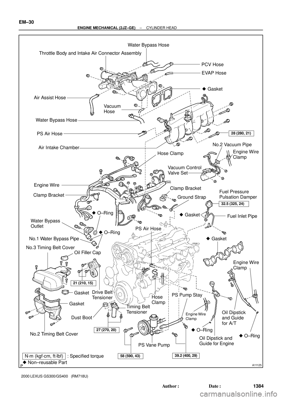
A11125
Throttle Body and Intake Air Connector AssemblyWater Bypass Hose
PCV Hose
EVAP Hose
� Gasket
Air Assist Hose
Vacuum
Hose
PS Air Hose
Air Intake Chamber
Engine Wire
Clamp
Drive Belt
TensionerClamp Bracket
Ground StrapFuel Pressure
Pulsation Damper Clamp Bracket
Water Bypass
Outlet
No.1 Water Bypass Pipe
No.3 Timing Belt Cover� O±Ring
Oil Filler CapFuel Inlet Pipe
PS Air Hose
Hose
Clamp
Timing Belt
Tensioner
PS Pump Stay
Oil Dipstick
and Guide
for A/T
PS Vane Pump Water Bypass Hose
28 (280, 21)
Engine Wire
� O±Ring
No.2 Timing Belt Cover
GasketGasket
21 (210, 15)
32.5 (325, 24)
� Gasket
� Gasket
Engine Wire
Clamp
� O±Ring � O±RingOil Dipstick and
Guide for Engine
27 (270, 20)
58 (590, 43)39.2 (400, 29)N´m (kgf´cm, ft´lbf) : Specified torque
� Non±reusable Part
Dust BootEngine Wire
Clamp
No.2 Vacuum Pipe
Hose Clamp
Vacuum Control
Valve Set
EM±30
± ENGINE MECHANICAL (2JZ±GE)CYLINDER HEAD
1384 Author�: Date�:
2000 LEXUS GS300/GS400 (RM718U)
Page 588 of 1111
CYLINDER BLOCK
1430 Author�: Date�:
2000 LEXUS GS300/GS400 (RM718U)
DISASSEMBLY
1. INSTALL ENGINE TO ENGINE STAND FOR
DISASSEMBLY
2. REMOVE GENE")
EM0DK±03
P02447
EM±76
± ENGINE MECHANICAL (2JZ±GE)CYLINDER BLOCK
1430 Author�: Date�:
2000 LEXUS GS300/GS400 (RM718U)
DISASSEMBLY
1. INSTALL ENGINE TO ENGINE STAND FOR
DISASSEMBLY
2. REMOVE GENERATOR
Remove the bolt, nut, pipe bracket and generator.
3. REMOVE TIMING BELT AND PULLEYS
(See page EM±16)
4. REMOVE NO.2 WATER BYPASS PIPE WITH HOSE
Remove the bolt, 2 nuts, No.2 water bypass pipe and gasket.
5. REMOVE WATER PUMP
Remove the 6 bolts, water pump and O±ring.
6. REMOVE CYLINDER HEAD (See page EM±33)
7. REMOVE OIL PRESSURE SWITCH AND KNOCK
SENSORS
Using SST, remove the switch and sensors.
SST 09816±30010
8. REMOVE OIL FILTER AND BRACKET ASSEMBLY
(a) Remove the union bolt and oil filter bracket.
(b) Remove the gasket from the union bolt.
(c) Remove the O±ring from the oil filter bracket.
9. REMOVE NO.1 OIL PIPE
Remove the union bolt, No.1 oil pipe and 2 gaskets.
10. REMOVE FUEL INLET PIPE
Remove the 2 bolts and fuel inlet pipe.
11. REMOVE LH ENGINE MOUNTING BRACKET AND
INSULATOR ASSEMBLY
Remove the 4 bolts and mounting bracket.
12. REMOVE RH ENGINE MOUNTING BRACKET AND
INSULATOR ASSEMBLY
Remove the 4 bolts and mounting bracket.
13. REMOVE OIL PUMP (See page LU±6)
14. REMOVE REAR OIL SEAL RETAINER
(a) Remove the 6 bolts of the retainer.
(b) Remove the oil seal retainer by prying the area between
the oil seal retainer and main bearing cap with a screw-
driver.
Page 607 of 1111
CYLINDER BLOCK
EM±95
1449 Author�: Date�:
2000 LEXUS GS300/GS400 (RM718U)
(c) Mark the front of t")
P02420
Painted Mark
90°90°
P02197
Seal Width
2 ± 3 mm
Seal
Packing
± ENGINE MECHANICAL (2JZ±GE)CYLINDER BLOCK
EM±95
1449 Author�: Date�:
2000 LEXUS GS300/GS400 (RM718U)
(c) Mark the front of the connecting rod cap bolt with paint.
(d) Retighten the connecting rod cap bolts 90° in the numeri-
cal order shown.
(e) Check that the painted mark is now at a 90° angle to the
front.
(f) Check that the crankshaft turns smoothly.
13. CHECK CONNECTING ROD THRUST CLEARANCE
(See page EM±76)
14. INSTALL REAR OIL SEAL RETAINER
(a) Remove any old packing (FIPG) material and be careful
not to drop any oil on the contact surfaces of the retainer
and cylinder block.
�Using a razor blade and gasket scraper, remove all
the old packing (FIPG) material from the gasket sur-
faces and sealing groove.
�Thoroughly clean all components to remove all de-
bris.
�Using a non±residue solvent, clean both sealing
surfaces.
(b) Apply seal packing to the retainer as shown in the illustra-
tion.
Seal packing: Part No.08826±00080 or equivalent
�Install a nozzle that has been cut to a 2 ± 3 mm (0.08
± 0.12 in.) opening.
�Parts must be assembled within 3 minutes of ap-
plication. Otherwise the material must be removed
and reapplied.
�Immediately remove nozzle from the tube and rein-
stall cap.
(c) Install the retainer with the 6 bolts.
Torque: 6.0 N´m (60 kgf´cm, 53 in.´lbf)
15. INSTALL OIL PUMP (See page LU±12)
16. INSTALL RH ENGINE MOUNTING BRACKET AND
INSULATOR ASSEMBLY
Install the mounting bracket with the 4 bolts.
Torque: 59 N´m (590 kgf´cm, 44 ft´lbf)
17. INSTALL LH ENGINE MOUNTING BRACKET AND
INSULATOR ASSEMBLY
Install the mounting bracket with the 4 bolts.
Torque: 59 N´m (590 kgf´cm, 44 ft´lbf)
18. INSTALL FUEL INLET PIPE
Install the fuel inlet pipe with the 2 bolts.
Torque: 29 N´m (290 kgf´cm, 21 ft´lbf)
19. INSTALL NO.1 OIL PIPE
Install the No.1 oil pipe with 2 new gaskets and the union bolt.
Torque: 55 N´m (550 kgf´cm, 41 ft´lbf)
Page 672 of 1111

ENGINE
INSPECTION
HINT:
Inspect these items when the engine is cold.
1. REPLACE TIMING BELT
(2JZ±GE EN")
MA004±04
B01384
± MAINTENANCEENGINE
MA±5
48 Author�: Date�:
2000 LEXUS GS300/GS400 (RM718U)
ENGINE
INSPECTION
HINT:
Inspect these items when the engine is cold.
1. REPLACE TIMING BELT
(2JZ±GE ENGINE: See page EM±16)
(1UZ±FE ENGINE: See page EM±14)
2. INSPECT DRIVE BELT
(2JZ±GE ENGINE: See page CH±1)
(1UZ±FE ENGINE: See page CH±1)
3. REPLACE SPARK PLUGS
(2JZ±GE ENGINE: See page IG±1)
(1UZ±FE ENGINE: See page IG±1)
4. INSPECT AIR FILTER
(a) Remove the air filter.
(b) Visually check that the air filter is not excessively dam-
aged or oily.
If necessary, replace the air filter.
(c) Clean the filter with compressed air.
First blow from the inside thoroughly, then blow the out-
side of the filter.
(d) Reinstall the air filter.
5. REPLACE AIR FILTER
Replace the air filter with a new one.
6. REPLACE ENGINE OIL AND OIL FILTER
(2JZ±GE ENGINE: See page LU±2)
(1UZ±FE ENGINE: See page LU±3)
7. REPLACE ENGINE COOLANT
(2JZ±GE ENGINE: See page CO±2)
(1UZ±FE ENGINE: See page CO±2)
8. REPLACE GASKET IN FUEL TANK CAP
(2JZ±GE ENGINE: See page EC±7)
(1UZ±FE ENGINE: See page EC±7)
9. INSPECT FUEL LINES AND CONNECTIONS
Visually check the fuel lines for cracks, leakage, loose connec-
tions, deformation or tank band looseness.
10. INSPECT EXHAUST PIPES AND MOUNTINGS
Visually check the pipes, hangers and connections for severe
corrosion, leaks or damage.
11. ADJUST VALVE CLEARANCE
(2JZ±GE ENGINE: See page EM±5)
(1UZ±FE ENGINE: See page EM±4)