Page 536 of 1111

EM0D1±05
A11132
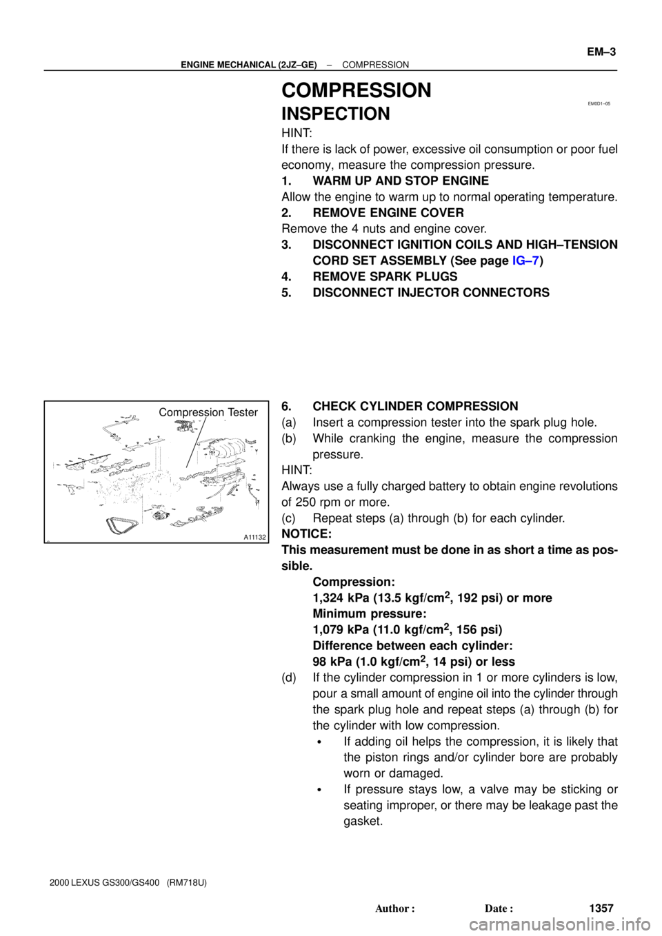
Compression Tester
± ENGINE MECHANICAL (2JZ±GE)COMPRESSION
EM±3
1357 Author�: Date�:
2000 LEXUS GS300/GS400 (RM718U)
COMPRESSION
INSPECTION
HINT:
If there is lack of power, excessive oil consumption or poor fuel
economy, measure the compression pressure.
1. WARM UP AND STOP ENGINE
Allow the engine to warm up to normal operating temperature.
2. REMOVE ENGINE COVER
Remove the 4 nuts and engine cover.
3. DISCONNECT IGNITION COILS AND HIGH±TENSION
CORD SET ASSEMBLY (See page IG±7)
4. REMOVE SPARK PLUGS
5. DISCONNECT INJECTOR CONNECTORS
6. CHECK CYLINDER COMPRESSION
(a) Insert a compression tester into the spark plug hole.
(b) While cranking the engine, measure the compression
pressure.
HINT:
Always use a fully charged battery to obtain engine revolutions
of 250 rpm or more.
(c) Repeat steps (a) through (b) for each cylinder.
NOTICE:
This measurement must be done in as short a time as pos-
sible.
Compression:
1,324 kPa (13.5 kgf/cm
2, 192 psi) or more
Minimum pressure:
1,079 kPa (11.0 kgf/cm
2, 156 psi)
Difference between each cylinder:
98 kPa (1.0 kgf/cm
2, 14 psi) or less
(d) If the cylinder compression in 1 or more cylinders is low,
pour a small amount of engine oil into the cylinder through
the spark plug hole and repeat steps (a) through (b) for
the cylinder with low compression.
�If adding oil helps the compression, it is likely that
the piston rings and/or cylinder bore are probably
worn or damaged.
�If pressure stays low, a valve may be sticking or
seating improper, or there may be leakage past the
gasket.
Page 590 of 1111

P04470
Z02391
Mark
1, 2, 3 , 4 or 5
Mark
1, 2 or 3
Mark
0, 1 or 2
No.1
No.2
No.3No.4No.5No.6
Number mark
12
22 33
1
Connecting rod cap
Crankshaft
Use bearing
EXAMPLE: Connecting rod cap º3º + Crankshaft º1º
= Total number 4 (Use bearing º4º)12 3
0120120
34 4 5 EM±78
± ENGINE MECHANICAL (2JZ±GE)CYLINDER BLOCK
1432 Author�: Date�:
2000 LEXUS GS300/GS400 (RM718U)
(i) Measure the Plastigage at its widest point.
Standard oil clearance:
STD0.023 ± 0.041 mm (0.0009 ± 0.0016 in.)
U/S 0.250.028 ± 0.066 mm (0.0011 ± 0.0026 in.)
Maximum oil clearance:
STD0.07 mm (0.0027 in.)
U/S 0.250.08 mm (0.0031 in.)
If the oil clearance is greater than maximum, replace the bear-
ings. If necessary, grind or replace the crankshaft.
HINT:
If using a standard bearing, replace with one having the same
number. If the number of the bearing cannot be determined, se-
lect the correct bearing by adding together the numbers im-
printed on the connecting rod cap and crankshaft, then select-
ing the bearing with the same number as the total. There are 5
sizes of standard bearings, marked º1º, º2º, º3º, º4º and º5º ac-
cordingly.
Reference
Connecting rod big end inside diameter:
Mark º1º55.025 ± 55.031 mm (2.1663 ± 2.1666 in.)
Mark º2º55.031 ± 55.037 mm (2.1666 ± 2.1668 in.)
Mark º3º55.037 ± 55.043 mm (2.1668 ± 2.1670 in.)
Crankshaft crank pin diameter:
Mark º0º51.994 ± 52.000 mm (2.0470 ± 2.0472 in.)
Mark º1º51.988 ± 51.994 mm (2.0468 ± 2.0470 in.)
Mark º2º51.982 ± 51.988 mm (2.0465 ± 2.0468 in.)
Standard sized bearing center wall thickness:
Mark º1º1.498 ± 1.501 mm (0.0590 ± 0.0591 in.)
Mark º2º1.501 ± 1.504 mm (0.0591 ± 0.0592 in.)
Mark º3º1.504 ± 1.507 mm (0.0592 ± 0.0593 in.)
Mark º4º1.507 ± 1.510 mm (0.0593 ± 0.0594 in.)
Mark º5º1.510 ± 1.513 mm (0.0594 ± 0.0596 in.)
(j) Completely remove the Plastigage.
Page 592 of 1111

P04792
Plastigage
P04468
A02784
Mark
0, 1, 2, 3, 4,
5, 6 or 7
1, 2, 3, 4 or 5Mark
0, 1, 2, 3, 4,
5, 6 or 7 No.1
No.5No.6
No.2
No.3
No.4No.7
No.1
No.2
Mark No.3
No.4No.5No.6No.7 (A)
(B)
Cylinder block (A)
Crankshaft (B) =+Total number º º : Number mark
Use bearing0±2 3±5 6±8 9±11 12±14
º2º º3º º1º º5ºº4º
EXAMPLE: Cylinder block º3º (A)
+ Crankshaft º4º (B)
= Total number 7 (Use bearing º3º) EM±80
± ENGINE MECHANICAL (2JZ±GE)CYLINDER BLOCK
1434 Author�: Date�:
2000 LEXUS GS300/GS400 (RM718U)
(g) Lay a strip of Plastigage across each journal.
(h) Install the main bearing caps. (See page EM±91)
Torque:
1st 45 N´m (450 kgf´cm, 33 ft´lbf)
2nd Turn extra 90°
NOTICE:
Do not turn the crankshaft.
(i) Remove the main bearing caps.
(See procedures (a) and (b) above)
(j) Measure the Plastigage at its widest point.
Standard clearance:
STD0.026 ± 0.040 mm (0.0010 ± 0.0016 in.)
U/S 0.250.025 ± 0.061 mm (0.0010 ± 0.0024 in.)
Maximum clearance:
STD0.06 mm (0.0024 in.)
U/S 0.250.08 mm (0.0031 in.)
If the oil clearance is greater than maximum, replace the bear-
ings. If necessary, grind or replace the crankshaft.
HINT:
If using a standard bearing, replace with one having the same
number. If the number of the bearing cannot be determined, se-
lect the correct bearing by adding together the numbers im-
printed on the cylinder block and crankshaft, then refer to the
table below for the appropriate bearing number. There are 5
sizes of standard bearings, marked º1º, º2º, º3º, º4º and º5º ac-
cordingly.