Page 115 of 1111

AT067±01
D01040
� Gasket
Clamp
ClampAir Cleaner, MAF Meter and Intake
Air Connector Pipe Assembly
Exhaust Manifold with TWC
Connector and
Wire Harness Level Gauge
Filler PipeAdjusting WasherPropeller Shaft Assembly
Shift Control Rod
Torque Converter ClutchPlug for Line
Pressure TestHeat Insulator
Heated Oxygen Sensor
Front and Center
Exhaust PipeFront Floor
Center Brace
Engine Under Cover Pipe Support BracketO±Ring Heat Insulator
� Gasket� Starterx6x839 (400, 29)
44 (450, 33)
72 (730, 53)
37 (380, 27)
13 (130, 9)
79 (805, 58)
37 (375, 27)
7.4 (75, 65 in.´lbf)
44 (450, 33)
44 (450, 33)
37 (380, 27)
37 (380, 27)
Hole Plug
5.4 (55, 48 in.´lbf)
Oil Cooler Pipe
x5
� O±Ring
5.4 (55, 48 in.´lbf)
� Gasket
44 (450, 33)
�
5.4 (55, 48 in.´lbf)
N´m (kgf´cm,ft´lbf) : Specified torque
� Non±reusable part� Gasket
48 (490, 35)
26 (270, 20)
44 (450, 33)
44 (450, 33)
�
79 (805, 58)
± AUTOMATIC TRANSMISSIONAUTOMATIC TRANSMISSION UNIT (2JZ±GE)
AT±27
1975 Author�: Date�:
2000 LEXUS GS300/GS400 (RM718U)
AUTOMATIC TRANSMISSION UNIT (2JZ±GE)
COMPONENTS
Page 117 of 1111

D01043
D01044
D01045
D01046
± AUTOMATIC TRANSMISSIONAUTOMATIC TRANSMISSION UNIT (2JZ±GE)
AT±29
1977 Author�: Date�:
2000 LEXUS GS300/GS400 (RM718U)
(e) Remove the 4 bolts and 2 gaskets from the tail pipe.
Torque: 44 N´m (450 kgf´cm, 33 ft´lbf)
HINT:
At the time of installation, please refer to the following item.
Replace the used gaskets with new ones.
(f) Disconnect the front and center exhaust pipe from the O±
ring and remove it.
8. REMOVE 2 HEAT INSULATORS
(a) Remove the 6 bolts and heat insulator.
Torque: 5.4 N´m (55 kgf´cm, 48 in.´lbf)
(b) Remove the 4 bolts and heat insulator.
Torque: 5.4 N´m (55 kgf´cm, 48 in.´lbf)
9. REMOVE PROPELLER SHAFT
(See page PR±4)
10. DISCONNECT SHIFT CONTROL ROD
Remove the nut and disconnect the rod.
Torque: 13 N´m (130 kgf´cm, 9 ft´lbf)
11. DISCONNECT OIL COOLER PIPE
(a) Loosen the 2 union nuts from the transmission.
Torque: 44 N´m (450 kgf´cm, 33 ft´lbf)
NOTICE:
Be careful not to damage the oil cooler pipe.
(b) Disconnect the 3 set bolts of the clamp.
Torque: 5.4 N´m (55 kgf´cm, 48 in.´lbf)
(c) Disconnect the 2 oil cooler pipes from the transmission.
Page 120 of 1111
AT05X±01
D01008
D01009
D01010
D01011
SST
± AUTOMATIC TRANSMISSIONEXTENSION HOUSING OIL SEAL
AT±3
1951 Author�: Date�:
2000 LEXUS GS300/GS400 (RM718U)
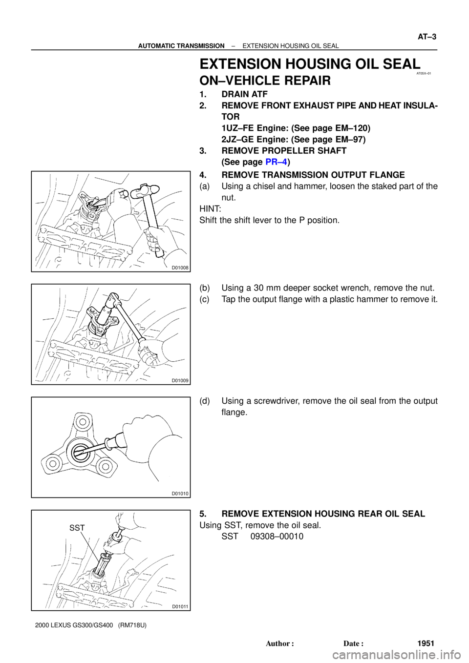
EXTENSION HOUSING OIL SEAL
ON±VEHICLE REPAIR
1. DRAIN ATF
2. REMOVE FRONT EXHAUST PIPE AND HEAT INSULA-
TOR
1UZ±FE Engine: (See page EM±120)
2JZ±GE Engine: (See page EM±97)
3. REMOVE PROPELLER SHAFT
(See page PR±4)
4. REMOVE TRANSMISSION OUTPUT FLANGE
(a) Using a chisel and hammer, loosen the staked part of the
nut.
HINT:
Shift the shift lever to the P position.
(b) Using a 30 mm deeper socket wrench, remove the nut.
(c) Tap the output flange with a plastic hammer to remove it.
(d) Using a screwdriver, remove the oil seal from the output
flange.
5. REMOVE EXTENSION HOUSING REAR OIL SEAL
Using SST, remove the oil seal.
SST 09308±00010
Page 121 of 1111
D01012
SST
Q08511
SST
D01009
D01008
AT±4
± AUTOMATIC TRANSMISSIONEXTENSION HOUSING OIL SEAL
1952 Author�: Date�:
2000 LEXUS GS300/GS400 (RM718U)
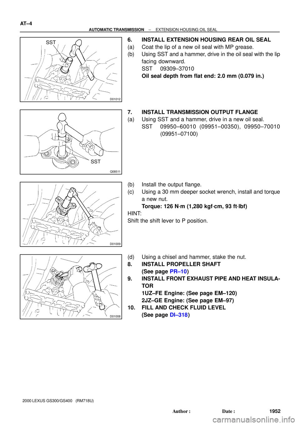
6. INSTALL EXTENSION HOUSING REAR OIL SEAL
(a) Coat the lip of a new oil seal with MP grease.
(b) Using SST and a hammer, drive in the oil seal with the lip
facing downward.
SST 09309±37010
Oil seal depth from flat end: 2.0 mm (0.079 in.)
7. INSTALL TRANSMISSION OUTPUT FLANGE
(a) Using SST and a hammer, drive in a new oil seal.
SST 09950±60010 (09951±00350), 09950±70010
(09951±07100)
(b) Install the output flange.
(c) Using a 30 mm deeper socket wrench, install and torque
a new nut.
Torque: 126 N´m (1,280 kgf´cm, 93 ft´lbf)
HINT:
Shift the shift lever to P position.
(d) Using a chisel and hammer, stake the nut.
8. INSTALL PROPELLER SHAFT
(See page PR±10)
9. INSTALL FRONT EXHAUST PIPE AND HEAT INSULA-
TOR
1UZ±FE Engine: (See page EM±120)
2JZ±GE Engine: (See page EM±97)
10. FILL AND CHECK FLUID LEVEL
(See page DI±318)
Page 123 of 1111

AT06A±01
D01049
Oil Cooler Pipe
Connector and Wire Harness
Level Gauge
Torque Converter Clutch
Flywheel Housing
Under CoverPlug for Line
Pressure Test
Front and Center Exhaust PipePropeller Shaft Assembly
Heated Oxygen Sensor
Pipe Support BracketRH Front TWC
Engine Under CoverHeat Insulator
Ground CableHeat Insulator � GasketO±Ring x6Adjusting Washer
Filler Pipe
44 (450, 33)
79 (805, 58)
37 (375, 27)
79 (805, 58)
13 (130, 9)
37 (380, 27)
18 (185, 13)
44 (450, 33)
44 (450, 33)
62 (630, 46)
62 (630, 46)
72 (730, 53)
37 (380, 27)
48 (490, 35)
44 (450, 33)44 (450, 33)
5.4 (55, 48 in.´lbf)
5.4 (55, 48 in.´lbf)
Heat Insulator
26 (270, 20)
� Gasket
LH Front TWC
44 (450, 33)
� Gasket
� Gasket
�
�� �
�
�
�
���
�
N´m (kgf´cm, ft´lbf) : Specified torque
Non±reusable part �Heat Insulator
5.4 (55, 48 in.´lbf)
44 (450, 33)
44 (450, 33)
� O±Ring
Heated Oxygen
SensorFront Floor
Center Brace
7.4 (75, 65 in.´lbf)
x6
± AUTOMATIC TRANSMISSIONAUTOMATIC TRANSMISSION UNIT (1UZ±FE)
AT±33
1981 Author�: Date�:
2000 LEXUS GS300/GS400 (RM718U)
AUTOMATIC TRANSMISSION UNIT (1UZ±FE)
COMPONENTS
Page 125 of 1111
D01052
D01044
D01002
D01053
D01004
± AUTOMATIC TRANSMISSIONAUTOMATIC TRANSMISSION UNIT (1UZ±FE)
AT±35
1983 Author�: Date�:
2000 LEXUS GS300/GS400 (RM718U)
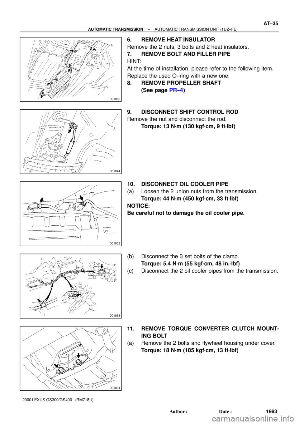
6. REMOVE HEAT INSULATOR
Remove the 2 nuts, 3 bolts and 2 heat insulators.
7. REMOVE BOLT AND FILLER PIPE
HINT:
At the time of installation, please refer to the following item.
Replace the used O±ring with a new one.
8. REMOVE PROPELLER SHAFT
(See page PR±4)
9. DISCONNECT SHIFT CONTROL ROD
Remove the nut and disconnect the rod.
Torque: 13 N´m (130 kgf´cm, 9 ft´lbf)
10. DISCONNECT OIL COOLER PIPE
(a) Loosen the 2 union nuts from the transmission.
Torque: 44 N´m (450 kgf´cm, 33 ft´lbf)
NOTICE:
Be careful not to damage the oil cooler pipe.
(b) Disconnect the 3 set bolts of the clamp.
Torque: 5.4 N´m (55 kgf´cm, 48 in.´lbf)
(c) Disconnect the 2 oil cooler pipes from the transmission.
11. REMOVE TORQUE CONVERTER CLUTCH MOUNT-
ING BOLT
(a) Remove the 2 bolts and flywheel housing under cover.
Torque: 18 N´m (185 kgf´cm, 13 ft´lbf)
Page 130 of 1111

AT05Y±01
D00910
Q07487
SST
AT0103
± AUTOMATIC TRANSMISSIONATF TEMPERATURE SENSOR
AT±5
1953 Author�: Date�:
2000 LEXUS GS300/GS400 (RM718U)
ATF TEMPERATURE SENSOR
ON±VEHICLE REPAIR
CAUTION:
When working with FIPG material, you must observe the follow-
ing items.
�Using a razor blade and gasket scraper, remove all the old
FIPG material from the gasket surfaces.
�Thoroughly clean all components to remove all the loose
material.
�Clean both sealing surfaces with a non±residue solvent.
�Apply FIPG in an approx. 1 mm (0.04 in.) wide bead along
the sealing surface.
�Parts must be assembled within 10 minutes of application.
Otherwise, the FIPG material must be removed and reap-
plied.
1. REMOVE DRAIN PLUG WITH GASKET AND DRAIN
AT F
2. REMOVE OIL PAN
NOTICE:
Some fluid will remain in the oil pan.
(a) Remove the 19 bolts.
(b) Install the blade of SST between the transmission case
and oil pan, cut off applied sealer, and remove the oil pan.
SST 09032±00100
NOTICE:
When removing the oil pan, be careful not to damage the oil
pan flange.
3. EXAMINE PARTICLES IN PAN
Remove the magnets and use them to collect steel particles.
Carefully look at the foreign matter and particles in the pan and
on the magnets to anticipate the type of wear you will find in the
transmission.
Steel (magnetic) ... bearing, gear and clutch plate wear
Brass (non±magnetic) ... bushing wear
Page 131 of 1111
D00752
D00753
D00909
D00916
D00909
AT±6
± AUTOMATIC TRANSMISSIONATF TEMPERATURE SENSOR
1954 Author�: Date�:
2000 LEXUS GS300/GS400 (RM718U)
4. REMOVE OIL STRAINER
NOTICE:
Be careful as some fluid will come out of the oil strainer.
(a) Remove the 4 bolts and oil strainer.
(b) Remove the 3 gaskets from the oil strainer.
5. REMOVE SOLENOID WIRING WITH ATF TEMPERA-
TURE SENSOR
(a) Disconnect the ATF temperature sensor.
(b) Remove the bolt and clamp.
(c) Disconnect the 7 connectors from the solenoid valves.
(d) Remove the bolt and pull out the solenoid connector.
6. INSTALL SOLENOID WIRING WITH ATF TEMPERA-
TURE SENSOR
(a) Install the solenoid connector with the bolt.
Torque: 5.4 N´m (55 kgf´cm, 48 in.´lbf)
(b) Connect the 7 connectors to the solenoid valves.
(c) Install the clamp with the bolt.
Torque: 6.4 N´m (65 kgf´cm, 56 in.´lbf)
(d) Connect the ATF temperature sensor.