Page 125 of 1111

AT±35
1983 Author�: Date�:
2000 LEXUS GS300/GS400 (RM718U)
6. REMOVE HEAT INSULATOR
Remove the 2 nu")
D01052
D01044
D01002
D01053
D01004
± AUTOMATIC TRANSMISSIONAUTOMATIC TRANSMISSION UNIT (1UZ±FE)
AT±35
1983 Author�: Date�:
2000 LEXUS GS300/GS400 (RM718U)
6. REMOVE HEAT INSULATOR
Remove the 2 nuts, 3 bolts and 2 heat insulators.
7. REMOVE BOLT AND FILLER PIPE
HINT:
At the time of installation, please refer to the following item.
Replace the used O±ring with a new one.
8. REMOVE PROPELLER SHAFT
(See page PR±4)
9. DISCONNECT SHIFT CONTROL ROD
Remove the nut and disconnect the rod.
Torque: 13 N´m (130 kgf´cm, 9 ft´lbf)
10. DISCONNECT OIL COOLER PIPE
(a) Loosen the 2 union nuts from the transmission.
Torque: 44 N´m (450 kgf´cm, 33 ft´lbf)
NOTICE:
Be careful not to damage the oil cooler pipe.
(b) Disconnect the 3 set bolts of the clamp.
Torque: 5.4 N´m (55 kgf´cm, 48 in.´lbf)
(c) Disconnect the 2 oil cooler pipes from the transmission.
11. REMOVE TORQUE CONVERTER CLUTCH MOUNT-
ING BOLT
(a) Remove the 2 bolts and flywheel housing under cover.
Torque: 18 N´m (185 kgf´cm, 13 ft´lbf)
Page 298 of 1111

INSPECTION
1. INSPECT HORN SWITCH
(a) Disconnect the negative (±) termina")
BE0FZ±08
I04195
I04196
6
I04197
BE±250
± BODY ELECTRICALHORN SYSTEM
2551 Author�: Date�:
2000 LEXUS GS300/GS400 (RM718U)
INSPECTION
1. INSPECT HORN SWITCH
(a) Disconnect the negative (±) terminal from the battery.
(b) Remove the left and right covers from the steering wheel.
(c) Using a torx socket wrench, loosen the 2 bolts.
(d) Pull up the horn pad and place it on the steering column,
as shown.
HINT:
Do not disconnect the connector from the horn pad.
(e) Disconnect the connector from the slip ring.
(f) Check that no continuity exists between terminal 6 of the
connector and body ground.
(g) Check that continuity exists between terminal 6 of the
connector and body ground when the horn contact plate
is pressed against the steering spoke assembly.
If continuity is not as specified, repair or replace the steering
wheel or wire harness as necessary.
(h) Install the horn pad in place and using a torx socket
wrench, torque the 2 bolts.
Torque:
7.1 N´m (72 kgf´cm, 62 in.´lbf)
(i) Install the left and right covers.
(j) Connect the negative (±) terminal to the battery.
2. INSPECT HORN OPERATION
Connect the positive (+) lead from the battery to the terminal
and negative (±) lead to the horn body and check that the horn
blows.
If operation is not as specified, replace the horn.
3. INSPECT HORN SWITCH CIRCUIT
(See page DI±806)
Page 406 of 1111
BR0JS±06
F01639
BR±28
± BRAKEREAR BRAKE CALIPER
2136 Author�: Date�:
2000 LEXUS GS300/GS400 (RM718U)
REMOVAL
1. REMOVE REAR WHEEL
Torque: 103 N´m (1,050 kgf´cm, 76 ft´lbf)
2. DISCONNECT FLEXIBLE HOSE
Remove the union bolt and gasket from the caliper, then discon-
nect the flexible hose from the caliper. Use a container to catch
brake fluid as it drains out.
Torque: 30 N´m (310 kgf´cm, 22 ft´lbf)
HINT:
At the time of installation, please refer to the following item.
Install the flexible hose lock securely in the lock hole in the cali-
per.
3. REMOVE CALIPER
(a) Remove the 2 installation bolts.
Torque: 104 N´m (1,065 kgf´cm, 77 ft´lbf)
(b) Remove the caliper.
4. REMOVE BRAKE PADS (See page BR±25)
(a) Remove the anti±squeal spring.
(b) Remove the clip and pad guide pin.
(c) Remove the 2 pads with the 4 anti±squeal shims.
Page 412 of 1111

DISASSEMBLY
1. REMOVE REAR WHEEL
Torque: 103 N´m (1,050 kgf´cm, 76 ft")
BR0JY±03
F01647
F01648
F01649
F01650
F01651
BR±34
± BRAKEPARKING BRAKE
2142 Author�: Date�:
2000 LEXUS GS300/GS400 (RM718U)
DISASSEMBLY
1. REMOVE REAR WHEEL
Torque: 103 N´m (1,050 kgf´cm, 76 ft´lbf)
2. REMOVE REAR DISC BRAKE ASSEMBLY
(a) Remove the 2 mounting bolts and remove the disc brake
assembly.
Torque: 104 N´m (1,065 kgf´cm, 77 ft´lbf)
(b) Suspend the disc brake securely and so the hose is not
stretched.
3. REMOVE DISC
(a) Release the parking brake pedal.
(b) Place matchmarks on the disc and rear axle hub.
(c) Remove the disc.
HINT:
�If the disc cannot be removed easily, turn the shoe adjust-
er until the wheel turns freely.
�If there are no matchmarks, temporarily install the disc,
then measure the disc runout and install the disc in posi-
tion (See page BR±30).
4. REMOVE SHOE RETURN SPRINGS
Using needle±nose pliers, remove the 2 shoe return springs.
5. REMOVE SHOE STRUT WITH SPRING
HINT:
At the time of reassembly, install the strut with the spring facing
forward.
6. REMOVE FRONT SHOE AND ADJUSTER
(a) Slide out the front shoe and remove the shoe adjuster.
(b) Disconnect the tension spring and remove the front shoe.
(c) Remove the 2 cups, shoe hold±down spring and pin.
7. REMOVE REAR SHOE AND TENSION SPRING
(a) Slide out the rear shoe.
(b) Remove the tension spring from the rear shoe.
(c) Disconnect the parking brake cable from the parking
brake shoe lever.
(d) Remove the 2 cups, shoe hold±down spring and pin.
Page 441 of 1111
BR0K2±06
F02814
F02815
BR±58
± BRAKEFRONT SPEED SENSOR
2166 Author�: Date�:
2000 LEXUS GS300/GS400 (RM718U)
REMOVAL
1. REMOVE FRONT WHEEL
Torque: 103 N´m (1,050 kgf´cm, 76 ft´lbf)
2. DISCONNECT SPEED SENSOR CONNECTOR
3. REMOVE SPEED SENSOR
(a) Remove the resin clip and 2 clamp bolts holding the sen-
sor harness to the body.
Torque: 5.0 N´m (51 kgf´cm, 44 in.´lbf)
(b) Remove the bolt and speed sensor from the steering
knuckle.
Torque: 8.0 N´m (82 kgf´cm, 71 in.´lbf)
Page 576 of 1111
ENGINE UNIT
1418 Author�: Date�:
2000 LEXUS GS300/GS400 (RM718U)
14. DISCONNECT PS PUMP AND A/C COMPRESSO")
A02823
A01483
A02794
A02791
A02789
Matchmark
Wire Clamp
EM±64
± ENGINE MECHANICAL (2JZ±GE)ENGINE UNIT
1418 Author�: Date�:
2000 LEXUS GS300/GS400 (RM718U)
14. DISCONNECT PS PUMP AND A/C COMPRESSOR
WITHOUT DISCONNECTING HOSES
(a) Disconnect the PS air hose from the No.4 timing belt cov-
er.
(b) Disconnect the PS air hose from the air intake chamber.
(c) Remove the 2 bolts and pump rear stay.
(d) Remove the 3 bolts and plate washer, and disconnect the
vane pump assembly from the engine.
(e) Loosen the nut.
(f) Using a torx socket (E10), remove the stud bolt and nut.
(g) Disconnect the PPS solenoid valve connector.
(h) Disconnect the A/C compressor connector.
(i) Remove the 2 bolts, and disconnect the compressor from
the engine.
HINT:
Put aside the vane pump and compressor, and suspend it se-
curely.
15. REMOVE PROPELLER SHAFT (See page PR±4)
16. REMOVE TRANSMISSION CONTROL ROD
Remove the 2 nuts and control rod.
17. DISCONNECT PS GEAR HOUSING
(a) Check the steering wheel at the straight±ahead position,
and place matchmarks on the sliding yoke and intermedi-
ate shaft.
(b) Remove the bolt holding the sliding yoke to the steering
intermediate shaft.
(c) Disconnect the PS pressure switch connector and wire
clamp.
Page 926 of 1111
SR0E3±03
F02565
± STEERINGPOWER STEERING GEAR
SR±45
2215 Author�: Date�:
2000 LEXUS GS300/GS400 (RM718U)
REMOVAL
NOTICE:
Remove the steering wheel assembly before the steering
gear removal, because there is possibility of breaking of
the spiral cable.
1. PLACE FRONT WHEELS FACING STRAIGHT AHEAD
2. REMOVE STEERING WHEEL PAD
(See page SR±11)
3. REMOVE STEERING WHEEL
(See page SR±11)
4. DISCONNECT RH AND LH TIE ROD ENDS
(See page SA±9)
5. DISCONNECT INTERMEDIATE SHAFT ASSEMBLY
(See page SR±11)
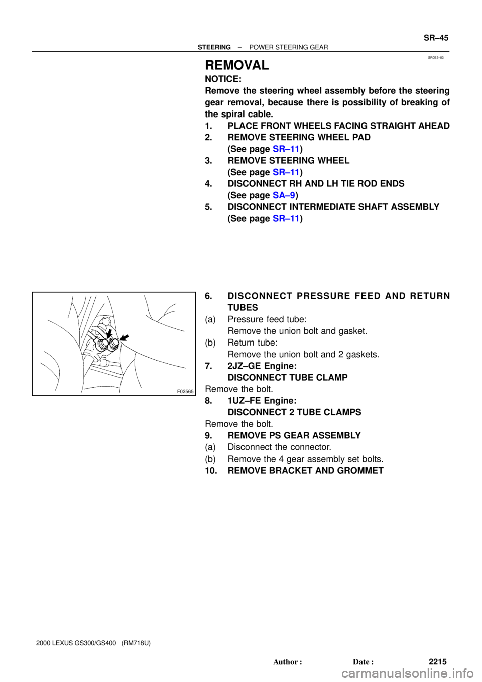
6. DISCONNECT PRESSURE FEED AND RETURN
TUBES
(a) Pressure feed tube:
Remove the union bolt and gasket.
(b) Return tube:
Remove the union bolt and 2 gaskets.
7. 2JZ±GE Engine:
DISCONNECT TUBE CLAMP
Remove the bolt.
8. 1UZ±FE Engine:
DISCONNECT 2 TUBE CLAMPS
Remove the bolt.
9. REMOVE PS GEAR ASSEMBLY
(a) Disconnect the connector.
(b) Remove the 4 gear assembly set bolts.
10. REMOVE BRACKET AND GROMMET
Page 938 of 1111

INSTALLATION
1. INSTALL GROMMET AND BRACKET
2. INSTALL PS GEAR ASSEMBLY
(a) Torque the 4 g")
SR0E7±01
F02565
± STEERINGPOWER STEERING GEAR
SR±57
2227 Author�: Date�:
2000 LEXUS GS300/GS400 (RM718U)
INSTALLATION
1. INSTALL GROMMET AND BRACKET
2. INSTALL PS GEAR ASSEMBLY
(a) Torque the 4 gear assembly set bolts.
Torque: 65 N´m (660 kgf´cm, 48 ft´lbf)
(b) Connect the connector.
3. 2JZ±GE Engine:
CONNECT TUBE CLAMP
Torque the bolt.
Torque: 5 N´m (55 kgf´cm, 48 in.´lbf)
4. 1UZ±FE Engine:
CONNECT 2 TUBE CLAMPS
Torque the bolt.
Torque: 5 N´m (55 kgf´cm, 48 in.´lbf)
5. CONNECT INTERMEDIATE SHAFT ASSEMBLY
(See page SR±17)
6. CONNECT PRESSURE FEED AND RETURN TUBES
(a) Pressure feed tube:
Torque the union bolt over a new gaskets.
Torque: 42 N´m (430 kgf´cm, 31 ft´lbf)
(b) Return tube:
Torque the union bolt with a new gasket on each side of
the tube.
Torque: 42 N´m (430 kgf´cm, 31 ft´lbf)
7. CONNECT RH AND LH TIE ROD ENDS
(See page SA±9)
8. POSITION FRONT WHEELS FACING STRAIGHT
AHEAD
HINT:
Do it with the front of the vehicle jacked up.
9. CENTER SPIRAL CABLE
(See page SR±17)
10. INSTALL STEERING WHEEL
(a) Align the matchmarks on the wheel and steering column
main shaft.
(b) Temporarily tighten the wheel set nut.
(c) Connect the connector.
11. BLEED POWER STEERING SYSTEM
(See page SR±3)
12. CHECK STEERING WHEEL CENTER POINT
13. TORQUE STEERING WHEEL SET NUT
Torque: 35 N´m (360 kgf´cm, 26 ft´lbf)
14. INSTALL STEERING WHEEL PAD
(See page SR±17)
15. CHECK FRONT WHEEL ALIGNMENT
(See page SA±4)