Page 254 of 1111

27 Noise NOISE PRODUCED BY VIBRATION OR SHOCK WHILE DRIVING
No
Ye s Is speaker properly installed?
Noise is produced from static eletricity accumulating in the vehicle body. With vehicles stationary lightly tap each system.
Is noise produced?Install properly.
Each system faulty. Is speaker properly installed?
No
No Ye s
Ye s
28 Noise NOISE PRODUCED WHEN ENGINE STARTS
NoYe s Whistling noise which becomes high±pitched when
accelerator strongly depressed, disappears shortly
after engine stops.Generator noise.
A/C noise.
Fuel gauge noise.
Horn noise.
Ignition noise.
Turn signal noise.
Washer noise.
Engine coolant temp. gauge noise.
Wiper noise. Whining noise occurs when A/C is operating.
Scratching noise occurs during sudden acceleration, driving on rough
roads or when ignition switch is turned ON.
Clicking sound is heard when horn button is pressed, then
released. Whirring/grating sound is heard when pushed
continuously.
Murmuring sound stops when engine stops.
Tick±tack noise occurs in co±ordination with blinking
offlasher.
Noise occurs during window washer operation.
Scratching noise occurs while engine is running,
and continues a while even after engine stops.
Scraping noise in line with wiper beat.
Other type of noiseYe s
Ye s
Ye s
Ye s
Ye s
Ye s
Ye s
Ye s No
No
No
No
No
No
No
No
± BODY ELECTRICALAUDIO SYSTEM
BE±215
2516 Author�: Date�:
2000 LEXUS GS300/GS400 (RM718U)
Page 642 of 1111

± INTRODUCTIONTERMS
IN±39
39 Author�: Date�:
2000 LEXUS GS300/GS400 (RM718U) OEM
Original Equipment Manufacturing
OHCOverhead Camshaft
OHVOverhead Valve
OPTOption
O/SOversize
P & BVProportioning And Bypass Valve
PCSPower Control System
PCVPositive Crankcase Ventilation
PKBParking Brake
PPSProgressive Power Steering
PSPower Steering
PTOPower Take±Off
R & PRack And Pinion
R/BRelay Block
RBSRecirculating Ball Type Steering
R/FReinforcement
RFSRigid Front Suspension
RHRight±Hand
RHDRight±Hand Drive
RLYRelay
ROMRead Only Memory
RrRear
RRRear±Engine Rear±Wheel Drive
RRSRigid Rear Suspension
RWDRear±Wheel Drive
SDNSedan
SENSensor
SICSStarting Injection Control System
SOCState Of Charge
SOHCSingle Overhead Camshaft
SPECSpecification
SPISingle Point Injection
SRSSupplemental Restraint System
SSMSpecial Service Materials
SSTSpecial Service Tools
STDStandard
STJCold±Start Fuel Injection
SWSwitch
SYSSystem
T/ATransaxle
TACHTachometer
TBIThrottle Body Electronic Fuel Injection
TCTurbocharger
TCCSTOYOTA Computer±Controlled System
TCVTiming Control Valve
TDCTop Dead Center
Page 812 of 1111

B01875
Fuel
Pump
Connector
B01998
New
Gasket
New
Gasket
FI1654
SST
Fulcrum Length
30 cm
± SFI (2JZ±GE)SFI SYSTEM
SF±3
1469 Author�: Date�:
2000 LEXUS GS300/GS400 (RM718U)
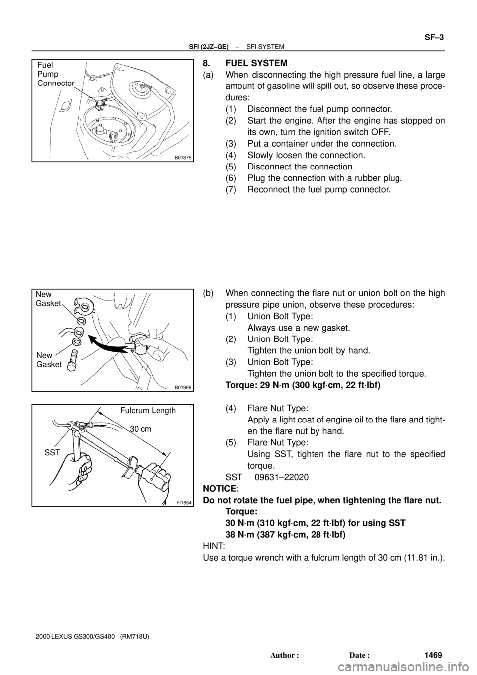
8. FUEL SYSTEM
(a) When disconnecting the high pressure fuel line, a large
amount of gasoline will spill out, so observe these proce-
dures:
(1) Disconnect the fuel pump connector.
(2) Start the engine. After the engine has stopped on
its own, turn the ignition switch OFF.
(3) Put a container under the connection.
(4) Slowly loosen the connection.
(5) Disconnect the connection.
(6) Plug the connection with a rubber plug.
(7) Reconnect the fuel pump connector.
(b) When connecting the flare nut or union bolt on the high
pressure pipe union, observe these procedures:
(1) Union Bolt Type:
Always use a new gasket.
(2) Union Bolt Type:
Tighten the union bolt by hand.
(3) Union Bolt Type:
Tighten the union bolt to the specified torque.
Torque: 29 N´m (300 kgf´cm, 22 ft´lbf)
(4) Flare Nut Type:
Apply a light coat of engine oil to the flare and tight-
en the flare nut by hand.
(5) Flare Nut Type:
Using SST, tighten the flare nut to the specified
torque.
SST 09631±22020
NOTICE:
Do not rotate the fuel pipe, when tightening the flare nut.
Torque:
30 N´m (310 kgf´cm, 22 ft´lbf) for using SST
38 N´m (387 kgf´cm, 28 ft´lbf)
HINT:
Use a torque wrench with a fulcrum length of 30 cm (11.81 in.).
Page 813 of 1111

P09286
New O±ring
CORRECT
WRONG Grommet
Injector
Delivery Pipe
B01575
O±Ring Delivery Pipe
Grommet
Spacer Insulator
O±Ring
B02046
Push
B02045
Push Pull
SF±4
± SFI (2JZ±GE)SFI SYSTEM
1470 Author�: Date�:
2000 LEXUS GS300/GS400 (RM718U)
(c) Observe these precautions when removing and installing
the injectors.
(1) Never reuse the O±ring.
(2) When placing a new O±ring on the injector, take
care not to damage it in any way.
(3) Coat a new O±ring with spindle oil or gasoline be-
fore installing±never use engine, gear or brake oil.
(d) Install the injector to the delivery pipe and intake manifold
as shown in the illustration.
Before installing the injector, must apply spindle oil or gas-
oline on the place where a delivery pipe or an intake man-
ifold touches an O±ring of the injector.
(e) Observe these precautions when disconnecting the fuel
tube connector (quick type):
(1) Check if there is any dirt like mud on the pipe and
around the connector before disconnecting them
and clean the dirt away.
(2) Be sure to disconnect with hands.
(3) When the connector and the pipe are stuck, push
and pull the connector to free to disconnect and pull
it out. Do not use any tool at this time.
(4) Inspect if there is any dirt or the likes on the seal sur-
face of the disconnected pipe and clean it away.
(5) Prevent the disconnected pipe and connector from
damaging and mixing foreign objects by covering
them with a vinyl bag.
(f) Observe these precautions when connecting the fuel
tube connector (quick type):
(1) Check if there is any damage or foreign objects on
the connected part of the pipe.
(2) Match the axis of the connector with axis of the pipe,
and push in the connector until the connector
makes a ºclickº sound. In case the connections is
tight, apply little amount of new engine oil on the tip
of the pipe.
Page 815 of 1111

SF0N4±01
B01876
B01877
Pull
Remove
Plug
B01878
B01874
Fuel
Sub Suction
Hose
± SFI (2JZ±GE)FUEL PUMP
SF±11
1477 Author�: Date�:
2000 LEXUS GS300/GS400 (RM718U)
REMOVAL
CAUTION:
Do not smoke or work near an open frame when working
the fuel pump.
1. REMOVE REAR SEAT CUSHION
2. REMOVE FLOOR SERVICE HOLE COVER
Remove the 3 cap nuts and service hole cover.
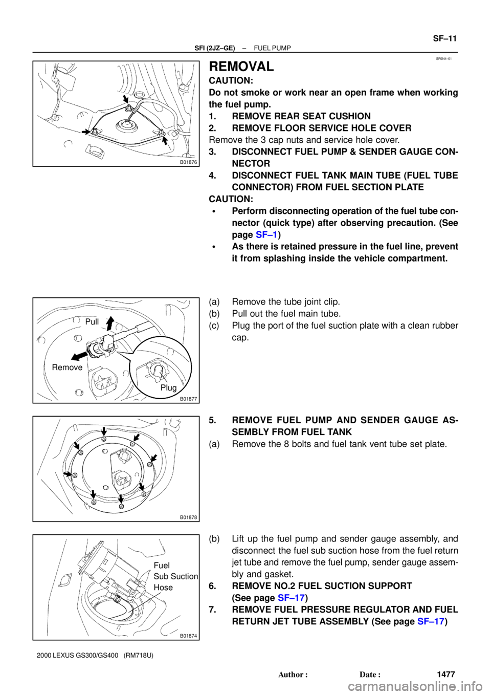
3. DISCONNECT FUEL PUMP & SENDER GAUGE CON-
NECTOR
4. DISCONNECT FUEL TANK MAIN TUBE (FUEL TUBE
CONNECTOR) FROM FUEL SECTION PLATE
CAUTION:
�Perform disconnecting operation of the fuel tube con-
nector (quick type) after observing precaution. (See
page SF±1)
�As there is retained pressure in the fuel line, prevent
it from splashing inside the vehicle compartment.
(a) Remove the tube joint clip.
(b) Pull out the fuel main tube.
(c) Plug the port of the fuel suction plate with a clean rubber
cap.
5. REMOVE FUEL PUMP AND SENDER GAUGE AS-
SEMBLY FROM FUEL TANK
(a) Remove the 8 bolts and fuel tank vent tube set plate.
(b) Lift up the fuel pump and sender gauge assembly, and
disconnect the fuel sub suction hose from the fuel return
jet tube and remove the fuel pump, sender gauge assem-
bly and gasket.
6. REMOVE NO.2 FUEL SUCTION SUPPORT
(See page SF±17)
7. REMOVE FUEL PRESSURE REGULATOR AND FUEL
RETURN JET TUBE ASSEMBLY (See page SF±17)