Page 196 of 1111
I04026
� Engine Room No.1 Junction Block
Fuses Relays
1. MAIN H±Fuse
2. FL ABS NO.1 H±Fuse
3. ALT H±Fuse
4. ABS NO.2 H±Fuse
5. H±LP CLN H±Fuse
6. RAD NO.1 Fuse
7. ALT±S Fuse
8. EFI Fuse
9. TURN HAZ Fuse
10. TEL Fuse
11. AM2 Fuse
13. HORN Fuse 12. ETCS Fuse
14. MPX±B Fuse
15. ECU±B1 Fuse
16. HTR FuseB. Starter Relay A. Headlight Control Relay
C. EFI Relay
17. FAN MAIN H±Fuse
18. CDS FAN H±Fuse
20. H±LP R LWR Fuse 19. RAD FAN H±Fuse
21. H±LP L LWR Fuse
22. H±LP R UPR Fuse
23. H±LP L UPR Fuse1
2 3 4 5 6 7 8 9 10 11 12 13
14 15
16 18 17 19
20 21 22 23 A
BC
± BODY ELECTRICALPOWER SOURCE
BE±17
2318 Author�: Date�:
2000 LEXUS GS300/GS400 (RM718U)
Page 197 of 1111
I04028
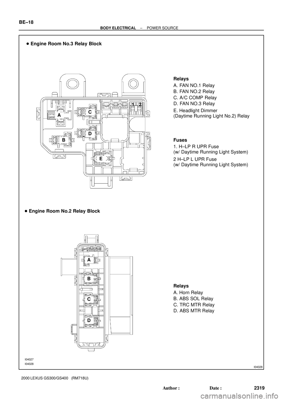
� Engine Room No.3 Relay Block
Relays
A. FAN NO.1 Relay
B. FAN NO.2 Relay
C. A/C COMP Relay
D. FAN NO.3 Relay
� Engine Room No.2 Relay Block
Relays
A. Horn Relay
B. ABS SOL Relay
C. TRC MTR Relay
D. ABS MTR Relay
I04027
I04028
A
B
C
D
EE. Headlight Dimmer
(Daytime Running Light No.2) Relay
A
B
C
DFuses
1. H±LP R UPR Fuse
(w/ Daytime Running Light System)
2 H±LP L UPR Fuse
(w/ Daytime Running Light System) 12 BE±18
± BODY ELECTRICALPOWER SOURCE
2319 Author�: Date�:
2000 LEXUS GS300/GS400 (RM718U)
Page 198 of 1111
I04029
Fuses
Relays 1. AM1 H±Fuse
2. WASHER Fuse
3. FOG Fuse
4. TAIL Fuse
B. Taillight Control Relay A. Fog Light Relay
C. Body ECU No.2 � Driver Side Instrument Panel Junction Block
5. SRS±ACC Fuse
6. GAUGE Fuse
7. FUEL OPN Fuse
8. D FR DOOR Fuse
9. PANEL Fuse
10. HTR Fuse
11. SRS±B Fuse
12. P/SEAT (D) Fuse
13. RAD NO.2 Fuse
14. WIP Fuse
15. OBD Fuse
16. STOP Fuse
17. CIG Fuse
18. ECU±IG Fuse
19. STARTER Fuse
20. IGN Fuse
21. D FR DOOR Fuse
2
21 34 5
678 9
10 11 12 13
14 15 16 17
18 19 20AB
C 1
± BODY ELECTRICALPOWER SOURCE
BE±19
2320 Author�: Date�:
2000 LEXUS GS300/GS400 (RM718U)
Page 199 of 1111
I04030
Fuses
Relays 1. DEF H±Fuse
2. ±
3. ±
4. MIR HTR Fuse
A. Ignition Main Relay
B. Mirror Heater Relay
E. Body ECU No.1 � Passenger Side Instrument Panel Junction Block
5. ±
6. ±
7. S/ROOF Fuse
8. P FR DOOR Fuse
9. ±
10. ±
11 .
12. P/SEAT (P) Fuse
13. DOME Fuse
14. SEAT HTR Fuse
15. ±
16. TV Fuse
17. ECU±B2 Fuse
18. ±
19. ±
20. ±
21. P FR DOOR Fuse
2
21 34 5
67 8 9
10 11 12 13
14 15 16 17
18 19 20AB
E
C. Defogger Relay
D. Heater Relay
CD
1
BE±20
± BODY ELECTRICALPOWER SOURCE
2321 Author�: Date�:
2000 LEXUS GS300/GS400 (RM718U)
Page 275 of 1111
BE0G0±05
1
CLOCK WILL NOT OPERATEPASSENGER SEAT BELT WARNING LIGHT DOES NOT OPERATE
I04264
Wire Harness Side5
4
3
6
1RAD NO.2 Fuse
DOME Fuse
Combination
Meter
Body ECU
No.2
Ground ACC
+B
PBEW
ILL
E Clock Assembly
± BODY ELECTRICALCLOCK
BE±227
2528 Author�: Date�:
2000 LEXUS GS300/GS400 (RM718U)
CLOCK
TROUBLESHOOTING
HINT:
Troubleshoot the clock according to the table below.
TroubleshootingNo.
Passenger seat belt warning light does not light up.1
Clock will not operate1
Clock loses or gains time2
± 1.5 seconds / day
INSPECT CLOCK CIRCUIT
(See page DI±849)
TROUBLESHOOTING NO.1
(a) Check that the battery positive voltage is 10 ± 16 V.
If voltage is not as specified, replace the battery.
(b) Check that the DOME and RAD NO.2 fuses are not
blown.
If the fuse is blown, replace the fuse and check for short.
(c) Troubleshoot the clock as follows.
HINT:
Inspect the connector on the wire harness side.
Page 448 of 1111
CHARGING SYSTEM
CH±1
1603 Author�: Date�:
2000 LEXUS GS300/GS400 (RM718U)
CHARGING S")
CH043±01
B01372
Except Maintenance±Free Battery
B01888
Maintenance±Free BatteryVoltmeter
± CHARGING (2JZ±GE)CHARGING SYSTEM
CH±1
1603 Author�: Date�:
2000 LEXUS GS300/GS400 (RM718U)
CHARGING SYSTEM
ON±VEHICLE INSPECTION
CAUTION:
�Check that the battery cables are connected to the
correct terminals.
�Disconnect the battery cables when the battery is giv-
en a quick charge.
�Do not do tests with a high voltage insulation resis-
tance tester.
�Never disconnect the battery while the engine is run-
ning.
1. CHECK BATTERY ELECTROLYTE LEVEL
Check the electrolyte quantity of each cell.
Maintenance±Free Battery:
If under the lower level, replace the battery (or add distilled wa-
ter if possible). Check the charging system.
Except Maintenance±Free Battery:
If under the lower level, add distilled water.
2. Except Maintenance±Free Battery:
CHECK BATTERY SPECIFIC GRAVITY
Check the specific gravity of each cell.
Standard specific gravity: 1.25 ± 1.29 at 20°C (68°F)
If the specific gravity is less than specification, charge the bat-
tery.
3. Maintenance±Free Battery:
CHECK BATTERY POSITIVE VOLTAGE
(a) After having driven the vehicle and in the case that 20
minutes have not passed after having stopped the en-
gine, turn the ignition switch ON and turn on the electrical
system (headlight, blower motor, rear defogger etc.) for
60 seconds to remove the surface charge.
(b) Turn the ignition switch OFF and turn off the electrical sys-
tems.
(c) Measure the battery positive voltage between the nega-
tive (±) and positive (+) terminals of the battery.
Standard voltage: 12.5 ± 12.9 V at 20°C (68°F)
If the voltage is less than specification, charge the battery.
4. CHECK BATTERY TERMINALS AND FUSES
(a) Check that the battery terminals are not loose or cor-
roded.
If the terminals are corroded, clean the terminals.
(b) Check the fusible link and fuses for continuity.
Page 480 of 1111

(±)
CO±24
± COOLING (2JZ±GE)ELECTRIC COOLING FAN
1562 Author�: Date�:
2000 LEXUS GS300/GS400 (RM718U)
ELECTRIC COOLI")
B01900
CO0AD±03
B00922
ECT
Switch
Connector
B02072
B02073
Ammeter
Battery(+)
(±)
CO±24
± COOLING (2JZ±GE)ELECTRIC COOLING FAN
1562 Author�: Date�:
2000 LEXUS GS300/GS400 (RM718U)
ELECTRIC COOLING FAN
ON±VEHICLE INSPECTION
1. CHECK COOLING FAN OPERATION WITH LOW
TEMPERATURE (Below 83°C (181°F))
(a) Turn the ignition switch ON.
(b) Check that the cooling fan stops.
If not, check the cooling fan relay and ECT switch, and check
for a separated connector or severed wire between the cooling
fan relay and ECT switch.
(c) Disconnect the ECT switch connector.
(d) Check that the cooling fan rotates.
If not, check the fuses, radiator fan main relay, cooling fan relay,
cooling fan, and check for a short circuit between the cooling
fan relay and ECT switch.
(e) Reconnect the ECT switch connector.
2. CHECK COOLING FAN OPERATION WITH HIGH
TEMPERATURE (Above 93°C (199°F))
(a) Start the engine, and raise coolant temperature to above
93°C (199°F).
HINT:
Coolant temperature is the detected value by the ECT switch
on the radiator lower tank.
(b) Check that the cooling fan rotates.
If not, replace the ECT switch.
3. INSPECT COOLING FANS
(a) Disconnect the cooling fan connector.
(b) Connect battery and ammeter to the cooling fan connec-
tor.
(c) Check that the cooling fan rotates smoothly, and check
the reading on the ammeter.
Standard amperage: 8.5 ± 11.5 A at 20°C (68°F)
(d) Reconnect the cooling fan connector.
Page 645 of 1111
BE1367
Medium Current Fuse and High Current Fuse
Equal Amperage Rating
V00076
Abbreviation Part Name Symbol Illustration
FUSE
MEDIUM CURRENT FUSE
HIGH CURRENT FUSE
FUSIBLE LINK
CIRCUIT BREAKERFUSE
M±FUSE
H±FUSE
FL
CB
± INTRODUCTIONREPAIR INSTRUCTIONS
IN±5
5 Author�: Date�:
2000 LEXUS GS300/GS400 (RM718U)
(3) Precoated parts are indicated in the component il-
lustrations by the º�º symbol.
(g) When necessary, use a sealer on gaskets to prevent
leaks.
(h) Carefully observe all specifications for bolt tightening
torques. Always use a torque wrench.
(i) Use of special service tools (SST) and special service ma-
terials (SSM) may be required, depending on the nature
of the repair. Be sure to use SST and SSM where speci-
fied and follow the proper work procedure. A list of SST
and SSM can be found in Preparation section in this
manual.
(j) When replacing fuses, be sure the new fuse has the cor-
rect amperage rating. DO NOT exceed the rating or use
one with a lower rating.