Page 653 of 1111

B00319
Recommended Viscosity (SAE):
TEMPERATURE RANGE ANTICIPATED BEFORE NEXT OIL CHANGE °F
°C±20
±29 0
±1820
±740
460
1680
27100
38 10W±30
5W±30 PREFERRED
LU05G±04
B01610
Oil PressureOil Pressure SwitchGauge
Union Bolt
P12478
Adhesive
± LUBRICATION (2JZ±GE)OIL AND FILTER
LU±1
1573 Author�: Date�:
2000 LEXUS GS300/GS400 (RM718U)
OIL AND FILTER
INSPECTION
1. CHECK OIL QUALITY
Check the oil for deterioration, entry of water, discoloring or thin-
ning.
If oil quality is visibly poor, replace the oil.
Oil grade:
API grade SJ, Energy±Conserving or ILSAC multi-
grade engine oil. SAE 5W±30 is the best choice for
your vehicle, for good fuel economy, and good start-
ing in cold weather.
2. CHECK ENGINE OIL LEVEL
After warming up the engine and then 5 minutes after the en-
gine stop, oil level should be between the low level and full level
marks of the dipstick.
If low, check for leakage and add oil up to the full level mark.
NOTICE:
Do not fill with engine oil above the full level mark.
3. REMOVE OIL PRESSURE SWITCH, AND INSTALL OIL
PRESSURE GAUGE
(a) Disconnect the oil pressure switch connector.
(b) Using SST, remove the oil pressure switch.
SST 09816±30010
(c) Install an oil pressure gauge.
4. WARM UP ENGINE
Allow the engine to warm up to normal operating temperature.
5. CHECK OIL PRESSURE
Oil pressure:
At idle49 kPa (0.5 kgf/cm2, 7 psi) or more
At 3,000 rpm324 kPa (3.3 kgf/cm2, 47 psi) or more
6. REMOVE OIL PRESSURE GAUGE AND REINSTALL
OIL PRESSURE SWITCH
(a) Remove the oil pressure gauge.
(b) Tighten the union bolt.
Torque: 90 N´m (900 kgf´cm, 66 ft´lbf)
(c) Apply adhesive to 2 or 3 threads of the oil pressure switch.
Adhesive:
Part No.08833±00080, THREE BOND 1344,
LOCTITE 242 or equivalent
(d) Using SST, install the oil pressure switch.
SST 09816±30010
Torque: 15 N´m (150 kgf´cm, 11 ft´lbf)
(e) Connect the oil pressure switch connector.
7. START ENGINE AND CHECK FOR LEAKS
Page 658 of 1111

Z17748
A
AB
BSeal Width
4 ± 5 mm
P02404
New Gasket
A02760
New O±Ring
Push
LU±14
± LUBRICATION (2JZ±GE)OIL PUMP
1586 Author�: Date�:
2000 LEXUS GS300/GS400 (RM718U)
�Using a non±residue solvent, clean both sealing
surfaces.
NOTICE:
Do not use a solvent which will affect the painted surfaces.
(b) Apply seal packing to the No.2 oil pan as shown in the il-
lustration.
Seal packing: Part No.08826±00080 or equivalent
�Install a nozzle that has been cut to a 4 ± 5 mm (0.16
± 0.20 in.) opening.
HINT:
Avoid applying an excessive amount to the surface.
�Parts must be assembled within 5 minutes of application.
Otherwise the material must be removed and reapplied.
�Immediately remove nozzle from the tube and reinstall
cap.
(c) Install the No.2 oil pan with the 16 bolts and 2 nuts.
Torque: 9.0 N´m (90 kgf´cm, 80 in.´lbf)
6. INSTALL OIL LEVEL SENSOR
(a) Install a new gasket to the level sensor.
(b) Install the level sensor with the 4 bolts.
Torque: 5.4 N´m (55 kgf´cm, 48 in.´lbf)
(c) Connect the level sensor connector.
7. INSTALL OIL DIPSTICK GUIDE AND DIPSTICK
(a) Install a new O±ring on the dipstick guide.
(b) Apply soapy water on the O±ring.
(c) Push in the dipstick guide into the guide hole of the No.1
oil pan.
(d) Install the dipstick guide with the bolt.
(e) Install the dipstick.
(f) Connect the engine wire clamp to the dipstick guide.
8. INSTALL CRANKSHAFT TIMING PULLEY, IDLER
PULLEY AND TIMING BELT (See page EM±23)
Page 661 of 1111
± LUBRICATION (2JZ±GE)OIL AND FILTER
LU±3
1575 Author�: Date�:
2000 LEXUS GS300/GS400 (RM718U)
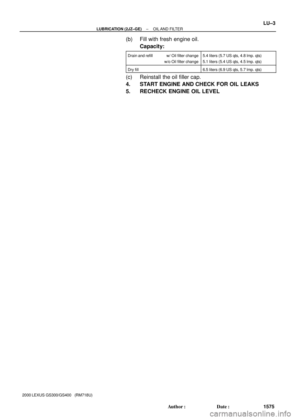
(b) Fill with fresh engine oil.
Capacity:
Drain and refill w/ Oil filter change
w/o Oil filter change5.4 liters (5.7 US qts, 4.8 lmp. qts)
5.1 liters (5.4 US qts, 4.5 lmp. qts)
Dry fill6.5 liters (6.9 US qts, 5.7 lmp. qts)
(c) Reinstall the oil filler cap.
4. START ENGINE AND CHECK FOR OIL LEAKS
5. RECHECK ENGINE OIL LEVEL
Page 662 of 1111
LU05I±01
B01978
No.3 Timing Belt Cover
Oil Filler Cap
Engine Wire Clamp Crankshaft Position Sensor
Oil Pump
Oil Level Sensor Connector
Oil Dipstick and Guide � O±Ring
Gasket � Crankshaft Front Oil Seal
Timing Belt Plate
No.2 Timing Belt Cover
Timing BeltOil Level Sensor
Oil Strainer Oil Pan Baffle Plate
Timing Belt Tensioner
Engine Oil Drain PlugTiming Belt Guide Drive Belt Tensioner
No.1 Timing Belt Cover
No.2 Oil Pan
Gasket
Idler Pulley
�35 (350, 26)
� O±Ring
� O±Ring
21 (210, 15)
x 9
8.0 (80, 71 in.´lbf)
x 5
� Gasketx 16
� Gasket
x 6 x 16
No.1 Oil Pan
Crankshaft Pulley
330 (3,300, 243)
27 (270, 20)
Dust Boot
Crankshaft Timing
Pulley
� Gasketx 6
N´m (kgf´cm, ft´lbf) : Specified torque
� Non±reusable part
� Precoated part
LU±4
± LUBRICATION (2JZ±GE)OIL PUMP
1576 Author�: Date�:
2000 LEXUS GS300/GS400 (RM718U)
OIL PUMP
COMPONENTS
Page 664 of 1111

LU05J±01
B01989
O±Ring
Pull
P10747
Z02375
SSTSST LU±6
± LUBRICATION (2JZ±GE)OIL PUMP
1578 Author�: Date�:
2000 LEXUS GS300/GS400 (RM718U)
REMOVAL
HINT:
When repairing the oil pump, the oil pan and strainer should be
removed and cleaned.
1. REMOVE ENGINE WITH TRANSMISSION
(See page EM±62)
2. SEPARATE ENGINE AND TRANSMISSION
(See page EM±62)
3. INSTALL ENGINE TO ENGINE STAND FOR
REMOVAL
4. REMOVE CRANKSHAFT POSITION SENSOR
5. REMOVE TIMING BELT, IDLER PULLEY AND CRANK-
SHAFT TIMING PULLEY (See page EM±16)
6. REMOVE OIL DIPSTICK AND GUIDE
(a) Disconnect the engine wire clamp from the dipstick guide.
(b) Remove the bolt.
(c) Pull out the dipstick guide together with the dipstick.
(d) Remove the O±ring from the dipstick guide.
7. REMOVE OIL LEVEL SENSOR
(a) Disconnect the level sensor connector.
(b) Remove the 4 bolts and level sensor.
(c) Remove the gasket from the level sensor.
NOTICE:
Be careful not to drop the oil level sensor when removing
it.
8. REMOVE NO.2 OIL PAN
(a) Remove the 16 bolts and 2 nuts.
(b) Insert the blade of SST between the No.1 and No.2 oil
pan, break the seal of the applied sealer and remove the
No.2 oil pan.
SST 09032±00100
NOTICE:
Be careful not to damage the No.2 oil pan contact surface
of the No.1 oil pan. Be careful not to damage the oil pan
flange.
Page 671 of 1111
MA003±06
MA±4
± MAINTENANCEUNDER HOOD
47 Author�: Date�:
2000 LEXUS GS300/GS400 (RM718U)
UNDER HOOD
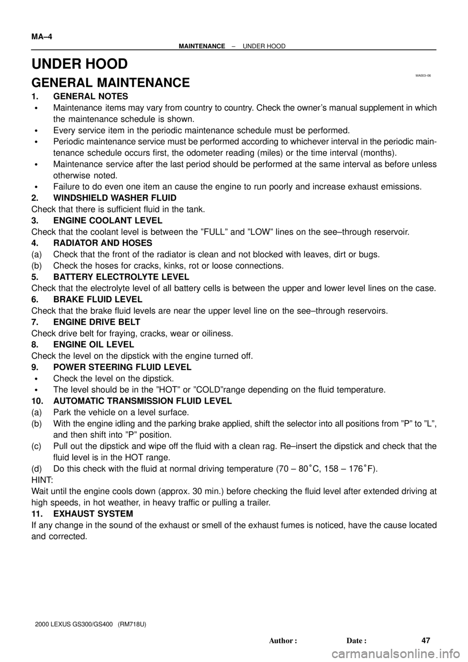
GENERAL MAINTENANCE
1. GENERAL NOTES
�Maintenance items may vary from country to country. Check the owner's manual supplement in which
the maintenance schedule is shown.
�Every service item in the periodic maintenance schedule must be performed.
�Periodic maintenance service must be performed according to whichever interval in the periodic main-
tenance schedule occurs first, the odometer reading (miles) or the time interval (months).
�Maintenance service after the last period should be performed at the same interval as before unless
otherwise noted.
�Failure to do even one item an cause the engine to run poorly and increase exhaust emissions.
2. WINDSHIELD WASHER FLUID
Check that there is sufficient fluid in the tank.
3. ENGINE COOLANT LEVEL
Check that the coolant level is between the ºFULLº and ºLOWº lines on the see±through reservoir.
4. RADIATOR AND HOSES
(a) Check that the front of the radiator is clean and not blocked with leaves, dirt or bugs.
(b) Check the hoses for cracks, kinks, rot or loose connections.
5. BATTERY ELECTROLYTE LEVEL
Check that the electrolyte level of all battery cells is between the upper and lower level lines on the case.
6. BRAKE FLUID LEVEL
Check that the brake fluid levels are near the upper level line on the see±through reservoirs.
7. ENGINE DRIVE BELT
Check drive belt for fraying, cracks, wear or oiliness.
8. ENGINE OIL LEVEL
Check the level on the dipstick with the engine turned off.
9. POWER STEERING FLUID LEVEL
�Check the level on the dipstick.
�The level should be in the ºHOTº or ºCOLDºrange depending on the fluid temperature.
10. AUTOMATIC TRANSMISSION FLUID LEVEL
(a) Park the vehicle on a level surface.
(b) With the engine idling and the parking brake applied, shift the selector into all positions from ºPº to ºLº,
and then shift into ºPº position.
(c) Pull out the dipstick and wipe off the fluid with a clean rag. Re±insert the dipstick and check that the
fluid level is in the HOT range.
(d) Do this check with the fluid at normal driving temperature (70 ± 80°C, 158 ± 176°F).
HINT:
Wait until the engine cools down (approx. 30 min.) before checking the fluid level after extended driving at
high speeds, in hot weather, in heavy traffic or pulling a trailer.
11. EXHAUST SYSTEM
If any change in the sound of the exhaust or smell of the exhaust fumes is noticed, have the cause located
and corrected.
Page 742 of 1111
PP0O2±02
± PREPARATIONBODY ELECTRICAL
PP±93
145 Author�: Date�:
2000 LEXUS GS300/GS400 (RM718U)
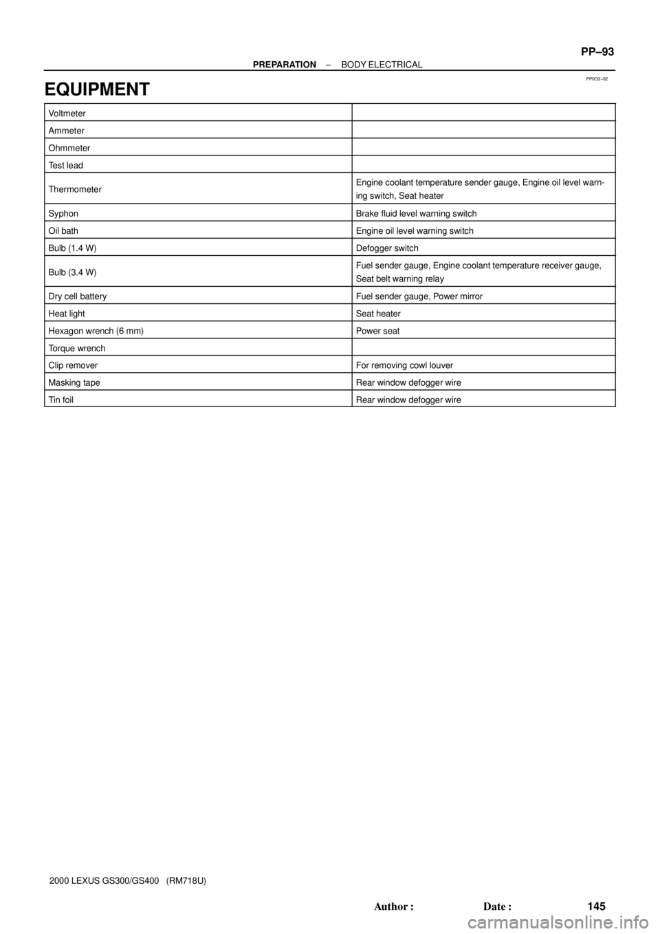
EQUIPMENT
Voltmeter
Ammeter
Ohmmeter
Test lead
ThermometerEngine coolant temperature sender gauge, Engine oil level warn-
ing switch, Seat heater
SyphonBrake fluid level warning switch
Oil bathEngine oil level warning switch
Bulb (1.4 W)Defogger switch
Bulb (3.4 W)Fuel sender gauge, Engine coolant temperature receiver gauge,
Seat belt warning relay
Dry cell batteryFuel sender gauge, Power mirror
Heat lightSeat heater
Hexagon wrench (6 mm)Power seat
Torque wrench
Clip removerFor removing cowl louver
Masking tapeRear window defogger wire
Tin foilRear window defogger wire
Page 769 of 1111
SS0DZ±02
SS±16
±
172 Author�: Date�:
TORQUE SPECIFICATION
Part tightenedN´mkgf´cmft´lbf
Union bolt x Cylinder block9090066
Oil pressure switch x Union bolt1515011
Oil drain plug x No.2 oil pan3838028
Oil pump body cover x Oil pump body101058
Plug x Oil pump body4950036
Oil pump x Cylinder block2121015
No.1 oil pan x Cylinder block 12 mm head
14 mm head21
40210
40015
30
Oil pan baffle plate x No.1 oil pan9.09080 in.´lbf
Oil strainer x No.1 oil pan9.09080 in.´lbf
No.2 oil pan x No.1 oil pan9.09080 in.´lbf
Oil level sensor x No.1 oil pan5.45548 in.´lbf
Crankshaft position sensor x Oil pump9.09080 in.´lbf