Page 411 of 1111
BR0JX±06
F04516
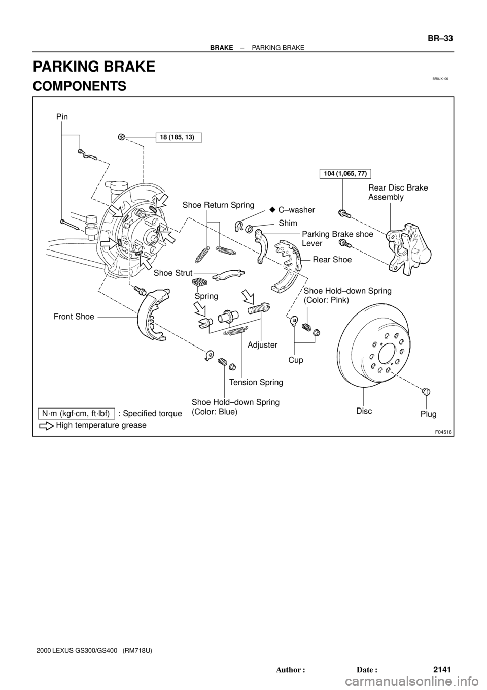
Pin
18 (185, 13)
Shoe Return Spring
104 (1,065, 77)
Rear Disc Brake
Assembly
Front Shoe
� C±washer
Shim
Parking Brake shoe
Lever
Rear Shoe
Shoe Strut
SpringShoe Hold±down Spring
(Color: Pink)
Adjuster
Cup
Tension Spring
Shoe Hold±down Spring
(Color: Blue)
DiscPlug
High temperature grease
N´m (kgf´cm, ft´lbf) : Specified torque
± BRAKEPARKING BRAKE
BR±33
2141 Author�: Date�:
2000 LEXUS GS300/GS400 (RM718U)
PARKING BRAKE
COMPONENTS
Page 548 of 1111
CYLINDER HEAD
EM±43
1397 Author�: Date�:
2000 LEXUS GS300/GS400 (RM718U)
(d")
EM2534
Overall
Length
EM0255
A02709
45° Carbide Cutter
Z00373
Width
P03966
Width 45°
15°
± ENGINE MECHANICAL (2JZ±GE)CYLINDER HEAD
EM±43
1397 Author�: Date�:
2000 LEXUS GS300/GS400 (RM718U)
(d) Check the valve overall length.
Standard overall length:
Intake98.29 ± 98.79 mm (3.8697 ± 3.8894 in.)
Exhaust98.84 ± 99.34 mm (3.8913 ± 3.9110 in.)
Minimum overall length:
Intake98.19 mm (3.8657 in.)
Exhaust98.74 mm (3.8874 in.)
If the overall length is less than minimum, replace the valve.
(e) Check the surface of the valve stem tip for wear.
If the valve stem tip is worn, resurface the tip with a grinder or
replace the valve.
NOTICE:
Do not grind off more than the minimum overall length.
7. INSPECT AND CLEAN VALVE SEATS
(a) Using a 45° carbide cutter, resurface the valve seats.
Remove only enough metal to clean the seats.
(b) Check the valve seating position.
Apply a thin coat of Prussian blue (or white lead) to the
valve face. Lightly press the valve against the seat. Do not
rotate the valve.
(c) Check the valve face and seat for the following:
�If blue appears 360° around the face, the valve is
concentric. If not, replace the valve.
�If blue appears 360° around the valve seat, the
guide and face are concentric. If not, resurface the
seat.
�Check that the seat contact is in the middle of the
valve face with the following width:
If not, correct the valve seats as follows:
Intake1.0 ± 1.4 mm (0.039 ± 0.055 in.)
Exhaust1.2 ± 1.6 mm (0.047 ± 0.063 in.)
(1) If the seating is too high on the valve face, use 15°
and 45° cutters to correct the seat.
Page 631 of 1111

V08423 Knock Sensor 1
GRECM
KNK
E1 12
E6
WIRING DIAGRAM
Wiring Diagram
This shows a wiring diagram of the circuit.
Use this diagram together with ELECTRICAL
WIRING DIAGRAM to thoroughly understand the
circuit.
Wire colors are indicated by an alphabetical code.
B = Black, L = Blue, R = Red, BR = Brown,
LG = Light Green, V = Violet, G = Green,
O = Orange, W = White, GR = Gray, P = Pink,
Y = Yellow, SB = Sky Blue
The first letter indicates the basic wire color and
the second letter indicates the color of the stripe.
DTC P0325Knock Sensor 1 Circuit Malfunction
CIRCUIT DESCRIPTION
Knock sensor is fitted to the cylinder block to detect engine knocking. This sensor contains a piezoelectric element which
generates a voltage when it becomes deformed, which occurs when the cylinder block vibrates due to knocking. If engine
knocking occurs, ignition timing is retarded to suppress it.
DTC No. DTC Detecting Condition Trouble Area
P0325No knock sensor 1 signal to ECM with engine speed,
1,200 rpm or more.� Open or short in knock sensor1 circuit
� Knock sensor 1 (looseness)
� ECM
If the ECM detects the above diagnosis conditions, it operates the fall safe function in which the corrective retard angle
value is set to the maximum value.
� Diagnostic Trouble Code No. and Detection Item
� Circuit Description
The major role and operation, etc. of the circuit
and its component parts are explained.
� Indicates the diagnostic trouble code, diagnostic
trouble code set parameter and suspect area of
the problem.
�
± INTRODUCTIONHOW TO TROUBLESHOOT ECU CONTROLLED
SYSTEMSIN±29
29 Author�: Date�:
2000 LEXUS GS300/GS400 (RM718U)
6. CIRCUIT INSPECTION
How to read and use each page is shown below.
Page 678 of 1111
PP0SN±01
PP±100
± PREPARATIONAIR CONDITIONING
152 Author�: Date�:
2000 LEXUS GS300/GS400 (RM718U)
AIR CONDITIONING
SST (Special Service Tools)
07110±58060Air Conditioner Service Tool Set
(07117±58060)Refrigerant Drain Service Valve
(07117±58070)T±Joint
(07117±58080)Quick Disconnect AdapterHigh pressure side
(07117±58090)Quick Disconnect AdapterLow pressure side
(07117±88060)Refrigerant Charging HoseHigh pressure side
(Color: Red)
(07117±88070)Refrigerant Charging HoseLow pressure side
(Color: Blue)
(07117±88080)Refrigerant Charging HoseUtility
(Color: Green)
07110±61050Wrench SetExpansion valve
(07111±21020)Holder
(07111±32020)Hexagon Wrench5 mm (0.20 in.)
07112±66040Magnetic Clutch Remover