Page 376 of 1111

I04079
Connector ºCº Connector ºDº
Connector ºFº Connector ºEº
Connector ºGº
1 131 13
1 201 12
± BODY ELECTRICALCOMBINATION METER
BE±93
2394 Author�: Date�:
2000 LEXUS GS300/GS400 (RM718U)
2. INSPECT COMBINATION METER CIRCUIT PLATE
Warning light circuit plate:
(a) Remove meter cover.
(b) Disconnect connectors ºCº, ºDº, ºEº, ºFº and ºGº from the
meter circuit plate and inspect the connectors on the wire
harness side as shown in the table.
Tester connectionCheck indicator lightSpecified condition
D10 (+) ± D12 (±)Fuel level warning lightContinuity
D6 (+) ± D8 (±)Headlight indiactor light (USA)
Taillight indiactor light (CANADA)Continuity
D2 (+) ± D4 (±)Hi±beam indicator lightContinuity
C3 (+) ± C7 (±)Engine oil level warning lightContinuity
C3 (+) ± C5 (±)Malfunction indicator lightContinuity
E19 (±) ± E20 (+)Slip warning lightContinuity
E18 (±) ± E20 (+)TRAC OFF indicator lightContinuity
E17 (±) ± E20 (+)Window washer level warning lightContinuity
E16 (±) ± E20 (+)ABS warning lightContinuity
E15 (±) ± E20 (+)VSC OFF indicator lightContinuity
E14 (±) ± E20 (+)Brake warning lightContinuity
E13 (±) ± E20 (+)ECT SNOW indicator lightContinuity
E12 (±) ± E20 (+)Low oil pressure warning lightContinuity
E11 (±) ± E20 (+)ECT PWR indicator lightContinuity
E10 (±) ± E20 (+)Discharge warning lightContinuity
E9 (±) ± E20 (+)CRUISE MAIN indicator lightContinuity
E8 (±) ± E20 (+)Seat belt warning lightContinuity
E7 (±) ± E20 (+)Rear Lights warning lightContinuity
E6 (±) ± E20 (+)Headlight leveling indiactorContinuity
E4 (+) ± E5 (±)SRS warning lightContinuity
E3 (±) ± E4 (+)Open door warning lightContinuity
F4 (±) ± F12 (+)A/T shift indicator light (L)Continuity
F11 (±) ± F12 (+)A/T shift indicator light (2)Continuity
F10 (±) ± F12 (+)A/T shift indicator light (3)Continuity
F8 (±) ± F12 (+)A/T shift indicator light (P)Continuity
Page 385 of 1111
Bright
(0W)
4
5
I01322
Battery Ignition
SwitchWarning Light
2 1 Wire Harness Side
I01323
1 2 OFF
ON
I01328
Battery Ignition
SwitchWarning Light
2 1 Wire Harness Side
I04107
12
4
OFF")
I04105
Dark
(10k W)Bright
(0W)
4
5
I01322
Battery Ignition
SwitchWarning Light
2 1 Wire Harness Side
I01323
1 2 OFF
ON
I01328
Battery Ignition
SwitchWarning Light
2 1 Wire Harness Side
I04107
12
4
OFF
ON BE±102
± BODY ELECTRICALCOMBINATION METER
2403 Author�: Date�:
2000 LEXUS GS300/GS400 (RM718U)
30. INSPECT LIGHT CONTROL RHEOSTAT OPERATION
Gradually, turn the rheostat knob from the bright side to dark
side and check that the resistance decreases from 10 kW to 0
W between terminal 4 and 5. (Rheostat knob turned to clock-
wise)
If operation is not as specified, replace the rheostat light control.
31. INSPECT WINDOW WASHER LEVEL WARNING
LIGHT
(a) Disconnect the connector from the warning switch and
ground terminal on the wire harness side connector.
(b) Engine running and check that the warning light lights up.
If the warning light does not light up, inspect the bulb or wire har-
ness.
32. INSPECT WINDOW WASHER LEVEL WARNING
SWITCH CONTINUITY
(a) Check that no continuity exists between the terminals with
the switch OFF (float up).
(b) Check that continuity exists between the terminals with
the switch ON (float down).
If operation is not as specified, replace the switch or inspect
ground point.
33. INSPECT SEAT BELT WARNING LIGHT
(a) Disconnect the connector from the retractor switch and
ground terminal on the wire harness side connector.
(b) Turn the ignition switch ON and check that the warning
light lights up.
If the warning light does not light up, inspect the bulb or wire har-
ness.
34. INSPECT SEAT BELT BUCKLE SWITCH CONTINUITY
(a) Check that continuity exists between the terminals 1 and
4 on the switch side connector with the switch ON (belt
fastened).
(b) Check that continuity exists between the terminals 2 and
4 on the switch side connector with the switch OFF (belt
unfastened).
If operation is not as specified, replace the switch.
Page 386 of 1111
I04108
Wire Harness Side
I04109
Press
Sensing part
± BODY ELECTRICALCOMBINATION METER
BE±103
2404 Author�: Date�:
2000 LEXUS GS300/GS400 (RM718U)
35. INSPECT SEAT BELT BUCKLE SWITCH CIRCUIT
Driver side: (See page DI±830)
Passenger side: (See page DI±785)
Disconnect the switch connector and inspect the connector on
wire harness side, as shown.
Tester connectionConditionSpecified condition
4 ± GroundConstantContinuity
If continuity is not as specified, inspect the circuits connected
to other parts.
36. Passenger seat only:
INSPECT SEAT BELT WARNING OCCUPANT DETEC-
TION SENSOR CONTINUITY
Check that continuity exists between the terminals 1 and 2
when pressing the sensing part.
If operation is not as specified, replace the sensor.
37. Passenger seat only:
INSPECT SEAT BELT WARNING OCCUPANT DETEC-
TION SENSOR CIRCUIT (See page DI±785)
Page 449 of 1111
CHARGING SYSTEM
1604 Author�: Date�:
2000 LEXUS GS300/GS400 (RM718U)
5. INSPECT DRIVE")
Z05962
B02027
Turn
B02028
Move
B01995
Type A
A
Type BB
AB
Z05963
CORRECT WRONG WRONG CH±2
± CHARGING (2JZ±GE)CHARGING SYSTEM
1604 Author�: Date�:
2000 LEXUS GS300/GS400 (RM718U)
5. INSPECT DRIVE BELT
HINT:
A belt tensioner is used, so checking the belt tension is not nec-
essary.
(a) Visually check the drive belt for excessive wear, frayed
cords, etc.
If necessary, replace the drive belt.
HINT:
�Cracks on the rib side of a drive belt are considered ac-
ceptable. If the drive belt has chunks missing from the
ribs, it should be replaced.
�The drive belt tension can be released by turning the belt
tensioner clockwise.
(b) Check the belt tensioner operation.
�Check that the belt tensioner moves downward
when the drive belt is pressed down at the points in-
dicated in the illustration with approx. 98 N (10 kgf,
22.0 lbf) of force.
�Check the alignment of the belt tensioner pulley to
make sure the drive belt will not slip off the pulley.
If necessary, replace the belt tensioner.
�Check that the arrow mark on the belt tensioner falls
within area A of the scale.
If it is outside area A, replace the drive belt.
HINT:
�When a new belt is installed, it should lie within area B. If
not, the drive belt is not correct.
�After installing a drive belt, check that it fits properly in the
ribbed grooves.
�Check by hand to confirm that the belt has not slipped out
of the groove on the bottom of the pulley.
6. VISUALLY CHECK GENERATOR WIRING AND
LISTEN FOR ABNORMAL NOISES
(a) Check that the wiring is in good condition.
(b) Check that there is no abnormal noise from the generator
while the engine is running.
Page 457 of 1111
CH044±01
B01996
Generator Wire
Pipe Clamp
A/T Oil Cooler PipePipe BracketGenerator Connector
Generator
Engine Under Cover
x 18
Drive Belt CH±4
± CHARGING (2JZ±GE)GENERATOR
1606 Author�: Date�:
2000 LEXUS GS300/GS400 (RM718U)
GENERATOR
COMPONENTS
Page 459 of 1111
CH045±01
B02027
Turn
B01646
B01962
Engine
Wire Clamp
Pipe Clamp
B01963
Pipe Bracket
CH±6
± CHARGING (2JZ±GE)GENERATOR
1608 Author�: Date�:
2000 LEXUS GS300/GS400 (RM718U)
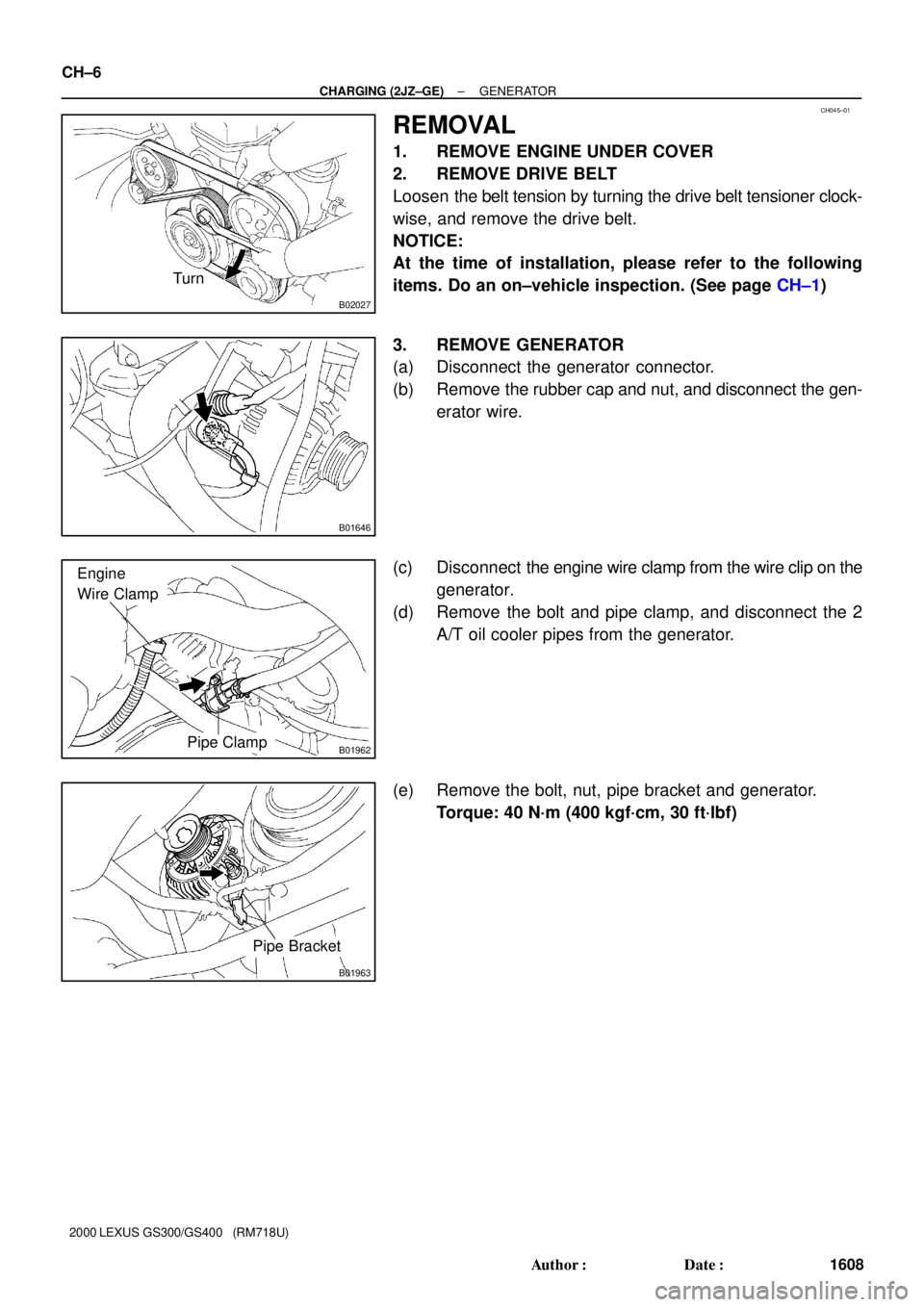
REMOVAL
1. REMOVE ENGINE UNDER COVER
2. REMOVE DRIVE BELT
Loosen the belt tension by turning the drive belt tensioner clock-
wise, and remove the drive belt.
NOTICE:
At the time of installation, please refer to the following
items. Do an on±vehicle inspection. (See page CH±1)
3. REMOVE GENERATOR
(a) Disconnect the generator connector.
(b) Remove the rubber cap and nut, and disconnect the gen-
erator wire.
(c) Disconnect the engine wire clamp from the wire clip on the
generator.
(d) Remove the bolt and pipe clamp, and disconnect the 2
A/T oil cooler pipes from the generator.
(e) Remove the bolt, nut, pipe bracket and generator.
Torque: 40 N´m (400 kgf´cm, 30 ft´lbf)
Page 486 of 1111
CO09Y±01
A02724
Air Cleaner Inlet
Upper Radiator Support
MAF Meter Connector Air Cleaner and MAF
Meter AssemblyLower Radiator Hose
Radiator
Assembly
ECM Outlet Duct
ECT
Switch
Engine Wire Clamp EVAP Hose
Lower Radiator Support
Intake Air Resonator
PS Pump
Front Bracket
Water Pump Pulley
Drive Belt
Engine Under CoverPS Vane Pump
Oil Cooler Hose
for A/T Electric Cooling
Fan Connector
Upper Radiator
Hose
x 18
58 (590, 43)
52 (530, 38)
N´m (kgf´cm, ft´lbf)
� Non±reusable part: Specified torqueWire Clamp
Upper Radiator
Support
± COOLING (2JZ±GE)WATER PUMP
CO±3
1541 Author�: Date�:
2000 LEXUS GS300/GS400 (RM718U)
WATER PUMP
COMPONENTS
Page 487 of 1111
B01985
Water Bypass Outlet
� O±Ring
Engine Wire
Water
Pump
Connector Bracket
Idler PulleyGasket
Timing Belt GuideNo.2 Water Bypass Pipe
Drain Hose
Timing Belt Tensioner
Timing Belt
Drive Belt TensionerOil Filler Cap
No.3 Timing Belt Cover
No.1 Water
Bypass Pipe
� Gasket
Crankshaft PulleyDust Boot
x 5 Thermostat
� O±Ring
� O±Ring
No.2 Timing Belt Cover
Gasket
No.1 Timing Belt Cover
� Gasket
Water Inlet
x 6
35 (350, 26)
21 (210, 15)
21 (210, 15)
27 (270, 20)�
N´m (kgf´cm, ft´lbf) : Specified torque
� Non±reusable part
� Precoated part
330 (3,300, 243)
Clamp Bracket
Crankshaft Position
Sensor Connector
Gasket
CO±4
± COOLING (2JZ±GE)WATER PUMP
1542 Author�: Date�:
2000 LEXUS GS300/GS400 (RM718U)