Page 531 of 1111
TIMING BELT
1382 Author�: Date�:
2000 LEXUS GS300/GS400 (RM718U)
20. INSTALL NO.2 TIMING BELT COVER
(a) Install the gasket on the timing")
A02803Plate Washer
A
B
A EM±28
± ENGINE MECHANICAL (2JZ±GE)TIMING BELT
1382 Author�: Date�:
2000 LEXUS GS300/GS400 (RM718U)
20. INSTALL NO.2 TIMING BELT COVER
(a) Install the gasket on the timing belt cover.
(b) Using a 5 mm hexagon wrench, install the timing belt cov-
er with the 3 bolts.
Torque: 8.0 N´m (80 kgf´cm, 71 in.´lbf)
21. INSTALL NO.3 TIMING BELT COVER
(a) Install the gasket on the timing belt cover.
(b) Using a 5 mm hexagon wrench, install the timing belt cov-
er with the 4 bolts.
Torque: 8.0 N´m (80 kgf´cm, 71 in.´lbf)
(c) Install the oil filler cap.
22. INSTALL PS PUMP AND FRONT BRACKET
(a) Temporarily install the vane pump to the bracket.
(b) Install the plate washer and front bracket with the 3 bolts.
Torque: 58 N´m (590 kgf´cm, 43 ft´lbf) for A bolts
52 N´m (530 kgf´cm, 38 ft´lbf) for B bolt
23. INSTALL DRIVE BELT (See page CH±1)
24. INSTALL RADIATOR ASSEMBLY (See page CO±23)
25. FILL ENGINE WITH COOLANT
26. START ENGINE CHECK FOR LEAKS
27. INSTALL ENGINE UNDER COVER
28. ROAD TEST
Check for abnormal noise, shock, slippage, correct shift points
and smooth operation.
29. RECHECK ENGINE COOLANT LEVEL
Page 532 of 1111
EM0D9±04
A09751
Air Cleaner,
MAF Meter
and Intake Air
Resonator
Assembly
PCV HoseExhaust Manifold
Case Clamp
PS Air
Hose
EVAP Hose
Air Cleaner InletMAF Meter
Connector
Heated Oxygen Sensor
Connector
� Clamp
40 (408, 32)
x 8
� Gasket
44 (440, 32)
44 (440, 32)
Pipe Support Bracket
Accelerator Cable
� Gasket
Upper Radiator
Hose
Front Exhaust Pipe
Drive Belt
Engine Under Cover
x 18
N´m (kgf´cm, ft´lbf) : Specified torque
� Non±reusable Part
Engine Cover
± ENGINE MECHANICAL (2JZ±GE)CYLINDER HEAD
EM±29
1383 Author�: Date�:
2000 LEXUS GS300/GS400 (RM718U)
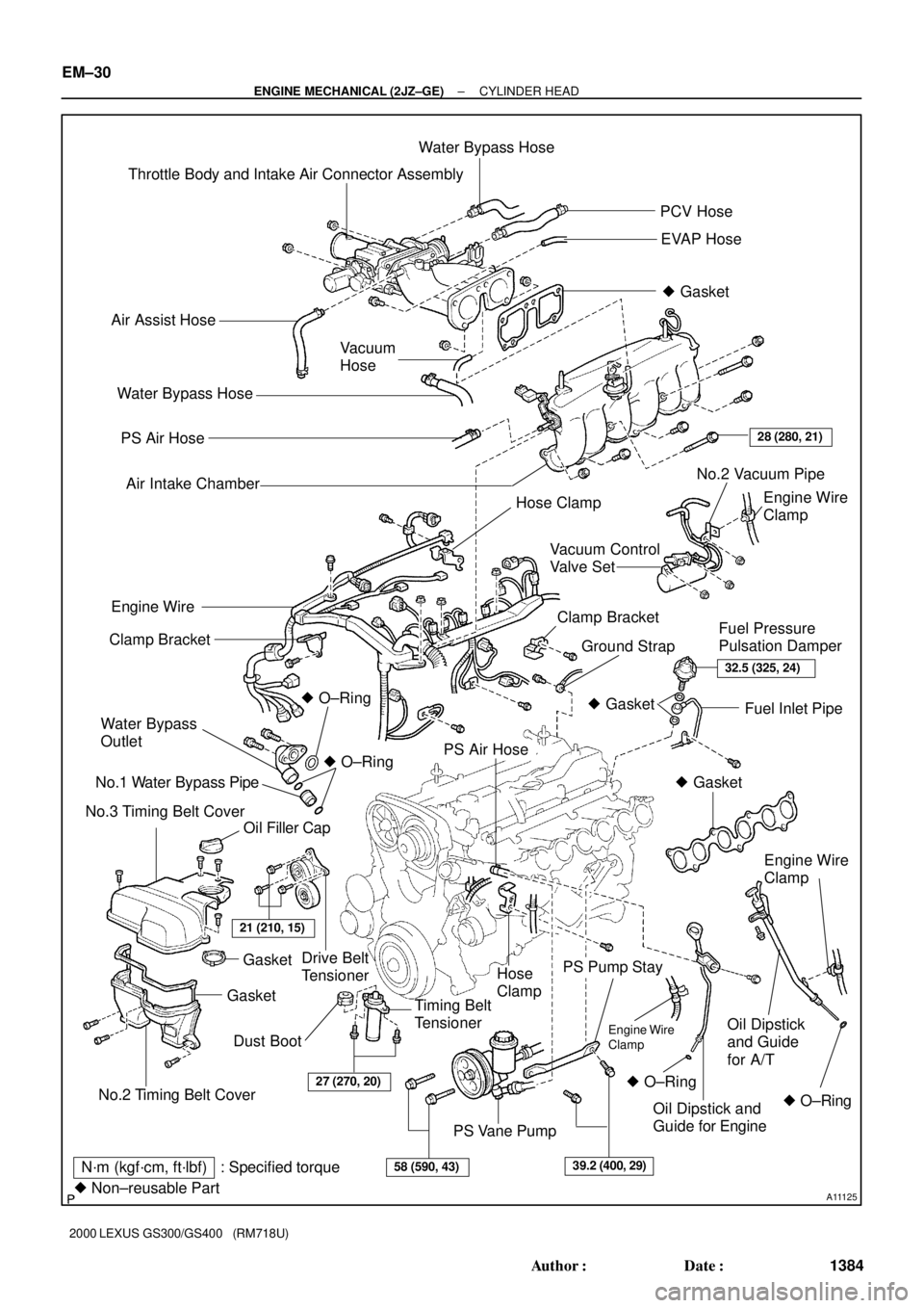
CYLINDER HEAD
COMPONENTS
Page 533 of 1111
A11125
Throttle Body and Intake Air Connector AssemblyWater Bypass Hose
PCV Hose
EVAP Hose
� Gasket
Air Assist Hose
Vacuum
Hose
PS Air Hose
Air Intake Chamber
Engine Wire
Clamp
Drive Belt
TensionerClamp Bracket
Ground StrapFuel Pressure
Pulsation Damper Clamp Bracket
Water Bypass
Outlet
No.1 Water Bypass Pipe
No.3 Timing Belt Cover� O±Ring
Oil Filler CapFuel Inlet Pipe
PS Air Hose
Hose
Clamp
Timing Belt
Tensioner
PS Pump Stay
Oil Dipstick
and Guide
for A/T
PS Vane Pump Water Bypass Hose
28 (280, 21)
Engine Wire
� O±Ring
No.2 Timing Belt Cover
GasketGasket
21 (210, 15)
32.5 (325, 24)
� Gasket
� Gasket
Engine Wire
Clamp
� O±Ring � O±RingOil Dipstick and
Guide for Engine
27 (270, 20)
58 (590, 43)39.2 (400, 29)N´m (kgf´cm, ft´lbf) : Specified torque
� Non±reusable Part
Dust BootEngine Wire
Clamp
No.2 Vacuum Pipe
Hose Clamp
Vacuum Control
Valve Set
EM±30
± ENGINE MECHANICAL (2JZ±GE)CYLINDER HEAD
1384 Author�: Date�:
2000 LEXUS GS300/GS400 (RM718U)
Page 534 of 1111
A11124
Ignition Coils and
High±Tension Cord
Assembly
GasketNo.2 Cylinder Head Cover
Camshaft Timing Oil Control ValveExhaust Camshaft
No.1 Camshaft Bearing Cap
Gasket
No.1 Cylinder Head Cover
No.2 Camshaft Bearing Cap x 6
x 24 x 6
20 (200, 15)
20 (200, 15)
Intake Camshaft
� O±Ring
� GasketOil Control Valve Filter
x 14 No.3 Camshaft Bearing Cap
No.1 Oil Pipe
See page EM±52
1st 35 (350, 25)
2nd Turn 90°
3rd Turn 90°
Heater Hose
55 (550, 41)
Union Bolt
18 (180, 13)Spark Plug
� Oil Seal
No.4 Timing Belt Cover
Camshaft Timing Pulley
Cylinder Head Assembly
Intake Manifold Assembly
Manifold Stay
� Cylinder Head Gasket
� Gasket
x 7
81 (810, 60)
15 (150, 11)
8.0 (80, 71 in.´lbf)
N´m (kgf´cm, ft´lbf) : Specified torque
� Non±reusable partx 12
28 (280, 21)
Starter Wire
Straight
Screw Plug
Timing Belt
± ENGINE MECHANICAL (2JZ±GE)CYLINDER HEAD
EM±31
1385 Author�: Date�:
2000 LEXUS GS300/GS400 (RM718U)
Page 538 of 1111
CYLINDER HEAD
EM±33
1387 Author�: Date�:
2000 LEXUS GS300/GS400 (RM718U)
REMOVAL
1. REMOVE ENGINE UNDER COVER
2. DRAI")
EM0DA±03
A02823
A02802
B01935
Wire
Grommet
Clamp
± ENGINE MECHANICAL (2JZ±GE)CYLINDER HEAD
EM±33
1387 Author�: Date�:
2000 LEXUS GS300/GS400 (RM718U)
REMOVAL
1. REMOVE ENGINE UNDER COVER
2. DRAIN ENGINE COOLANT
3. DISCONNECT UPPER RADIATOR HOSE FROM WA-
TER OUTLET
4. REMOVE ENGINE COVER
Remove the 4 nuts and engine cover.
5. REMOVE AIR CLEANER INLET
6. REMOVE AIR CLEANER, MAF METER AND INTAKE
AIR RESONATOR ASSEMBLY (See page EM±62)
7. REMOVE DRIVE BELT (See page CH±1)
8. DISCONNECT PS PUMP WITHOUT DISCONNECTING
HOSES
(a) Disconnect the PS air hose from the No.4 timing belt cov-
er.
(b) Disconnect the PS air hose from the air intake chamber.
(c) Remove the 2 bolts and pump rear stay.
(d) Remove the 2 bolts, and disconnect the vane pump from
the pump bracket.
HINT:
Put aside the vane pump, and suspend it.
9. DISCONNECT FRONT EXHAUST PIPE FROM EX-
HAUST MANIFOLD
(a) Disconnect the wire grommet and sensor wire of the
heated oxygen sensor (bank 2 sensor 2) from the hole
and clamp on the floor.
Page 539 of 1111
CYLINDER HEAD
1388 Author�: Date�:
2000 LEXUS GS300/GS400 (RM718U)
(b) Remove the 3 bolts and nuts holding the front exhaust
pipe to the exh")
A02819
A09752
A02735
EM±34
± ENGINE MECHANICAL (2JZ±GE)CYLINDER HEAD
1388 Author�: Date�:
2000 LEXUS GS300/GS400 (RM718U)
(b) Remove the 3 bolts and nuts holding the front exhaust
pipe to the exhaust manifold.
(c) Remove the 2 bolts and pipe support bracket.
(d) Disconnect the front exhaust pipe from the exhaust man-
ifold, and remove the 2 gaskets.
10. REMOVE EXHAUST MANIFOLD
(a) Disconnect the 3 heated oxygen sensor connectors and
clamp.
(b) Remove the clamp and case clamp.
(c) Using a 14 mm deep socket wrench, remove the 8 nuts,
exhaust manifold and 2 gaskets.
11. REMOVE WATER BYPASS OUTLET AND NO.1
WATER BYPASS PIPE (See page CO±11)
12. REMOVE THROTTLE BODY AND INTAKE AIR
CONNECTOR ASSEMBLY (See page EM±5)
13. REMOVE OIL DIPSTICK AND GUIDE FOR ENGINE
(See page LU±6)
14. REMOVE OIL DIPSTICK AND GUIDE FOR A/T
(See page EM±62)
15. REMOVE AIR INTAKE CHAMBER (See page SF±46)
16. REMOVE VACUUM CONTROL VALVE SET AND NO.2
VACUUM PIPE
(a) Disconnect the VSV connector for the ACIS.
(b) Remove the 3 nuts, vacuum control valve set and No.2
vacuum pipe.
(c) Disconnect the engine wire clamp from the clamp bracket
of the No.2 vacuum pipe.
17. REMOVE NO.3 TIMING BELT COVER
18. REMOVE IGNITION COILS AND HIGH±TENSION
CORD SET ASSEMBLY (See page IG±7)
19. REMOVE SPARK PLUGS
Page 541 of 1111
CYLINDER HEAD
1390 Author�: Date�:
2000 LEXUS GS300/GS400 (RM718U)
22. REMOVE INTAKE MANIFOLD ASSEMBLY
(a) Disconnect the star")
A11122
A02713
A02836
S03013
A02647
EM±36
± ENGINE MECHANICAL (2JZ±GE)CYLINDER HEAD
1390 Author�: Date�:
2000 LEXUS GS300/GS400 (RM718U)
22. REMOVE INTAKE MANIFOLD ASSEMBLY
(a) Disconnect the starter wire from the manifold stay.
(b) Remove the 2 bolts and manifold stay.
(c) Remove the 7 bolts, 2 nuts, intake manifold and delivery
pipe assembly and gasket.
23. REMOVE NO.1 AND NO.2 CYLINDER HEAD COVERS
(a) Remove the 12 bolts and 4 nuts.
(b) Remove the cylinder head covers and gaskets.
24. DISCONNECT TIMING BELT FROM CAMSHAFT TIM-
ING PULLEYS (See page EM±16)
NOTICE:
�Support the timing belt, so that the measuring of the
crankshaft timing pulley and timing belt does not
shift.
�Be careful not to drop anything inside the timing belt
cover.
�Do not allow the timing belt to come into contact with
oil, water or dust.
25. REMOVE CAMSHAFT TIMING PULLEYS
(a) Remove the exhaust camshaft timing pulley.
Hold the hexagon portion of the camshaft with a wrench, and
remove the pulley bolt and camshaft pulley.
(b) Remove the VVT±i (intake camshaft timing) pulley.
(See page EM±16)
26. REMOVE NO.4 TIMING BELT COVER
Remove the 4 bolts and timing belt cover.
Page 556 of 1111
VALVE CLEARANCE
1360 Author�: Date�:
2000 LEXUS GS300/GS400 (RM718U)
5. REMOVE NO.3 TIMING BELT COVER
Using a 5 mm hex")
A02638
A02651
A02664
EX
IN135
24
135
24 1 1
EM±6
± ENGINE MECHANICAL (2JZ±GE)VALVE CLEARANCE
1360 Author�: Date�:
2000 LEXUS GS300/GS400 (RM718U)
5. REMOVE NO.3 TIMING BELT COVER
Using a 5 mm hexagon wrench, remove the 4 bolts, oil filler cap,
timing belt cover and gasket.
6. REMOVE IGNITION COILS AND HIGH±TENSION
CORD SET ASSEMBLY (See page IG±7)
7. REMOVE SPARK PLUGS
8. DISCONNECT ENGINE WIRE FROM CYLINDER HEAD
COVERS
9. REMOVE CYLINDER HEAD COVERS
(See page EM±33)
10. SET NO.1 CYLINDER TO TDC/COMPRESSION
(a) Turn the crankshaft pulley and align its groove with the
timing mark º0º of the No.1 timing belt cover.
NOTICE:
Always turn the crankshaft clockwise.
(b) Check that the timing marks of the camshaft timing pul-
leys are aligned with the timing marks of the No.4 timing
belt cover.
If not, turn the crankshaft 1 revolution (360°).
11. INSPECT VALVE CLEARANCE
(a) Check only those valves indicated in the illustration.
�Using a feeler gauge, measure the clearance be-
tween the valve lifter and camshaft.
�Record the valve clearance measurements of those
that are out of specification. They will be used later
to determine the required replacement adjusting
shim.
Valve clearance (Cold):
Intake0.15 ± 0.25 mm(0.006 ± 0.010 in.)
Exhaust0.25 ± 0.35 mm (0.010 ± 0.014 in.)
(b) Turn the crankshaft pulley 1 revolution (360°), and align
the groove with the timing mark º0º of the No.1 timing belt
cover.