Page 493 of 1111
WATER PUMP
CO±5
1543 Author�: Dat")
CO09Z±03
A02725Turn
Loosen
B01614
Water Bypass Outlet
No.1 Water Bypass Hose
B01638
Clamp Bracket
Connector Bracket
B01572No.2 Water Bypass Pipe
± COOLING (2JZ±GE)WATER PUMP
CO±5
1543 Author�: Date�:
2000 LEXUS GS300/GS400 (RM718U)
REMOVAL
1. REMOVE RADIATOR ASSEMBLY
(See page CO±18)
2. REMOVE DRIVE BELT AND WATER PUMP PULLEY
(a) Loosen the 4 nuts holding the water pump pulley to the
water pump.
(b) Loosen the drive belt tension by turning the drive belt ten-
sioner clockwise, and remove the drive belt.
(c) Remove the 4 nuts and water pump pulley.
3. REMOVE TIMING BELT AND IDLER PULLEY
(See page EM±16)
4. REMOVE WATER BYPASS OUTLET AND NO.1
WATER BYPASS PIPE
(a) Remove the 2 bolts, water bypass outlet and No.1 water
bypass pipe.
(b) Remove the 3 O±rings from the water bypass outlet and
No.1 water bypass pipe.
5. REMOVE WATER INLET AND THERMOSTAT
(See page CO±11)
6. REMOVE WATER PUMP
(a) Loosen the nut and remove the bolt, slide the generator
away from the water pump.
(b) Remove the bolt, and disconnect the clamp bracket (for
engine wire).
(c) Remove the bolt, and disconnect the connector bracket
(for crankshaft position sensor connector).
(d) Remove the 2 nuts, and disconnect the No.2 water by-
pass pipe from the water pump.
Page 496 of 1111
WATER PUMP
1546 Author�: Date�:
2000 LEXUS GS300/GS400 (RM718U)
INSTALLATION
1. INST")
CO0A1±03
P03945
New
O±Ring
P02574
New Gasket
A02801
AB A
B
A
B
B
B
B01614
New O±Ring
CO±8
± COOLING (2JZ±GE)WATER PUMP
1546 Author�: Date�:
2000 LEXUS GS300/GS400 (RM718U)
INSTALLATION
1. INSTALL WATER PUMP
(a) Install a new O±ring to the cylinder block.
(b) Install the drain hose.
(c) Install a new gasket to the water pump.
(d) Connect the water pump to the water bypass pipe. Do not
install the nut yet.
(e) Install the water pump with the 2 bolts (A) and 4 bolts (B).
Torque: 21 N´m (210 kgf´cm, 15 ft´lbf)
HINT:
Hand tighten the (A) bolts first.
(f) Install the 2 nuts holding the No.2 water bypass pipe to
the water pump.
Torque: 21 N´m (210 kgf´cm, 15 ft´lbf)
(g) Install the connector bracket (for crankshaft position sen-
sor connector) with the bolt.
(h) Install the clamp bracket (for engine wire) with the bolt.
(i) Install the generator with the bolt and nut.
Torque: 40 N´m (400 kgf´cm, 30 ft´lbf)
2. INSTALL THERMOSTAT AND WATER INLET
(See page CO±13)
3. INSTALL NO.1 WATER BYPASS PIPE AND WATER
BYPASS OUTLET
(a) Install 2 new O±rings to the No.1 water bypass pipe.
(b) Install a new O±ring and the water bypass outlet with the
2 bolts.
Torque: 9.0 N´m (90 kgf´cm, 80 in.´lbf)
4. INSTALL IDLER PULLEY AND TIMING BELT
(See page EM±23)
5. INSTALL WATER PUMP PULLEY AND DRIVE BELT
Torque: 14 N´m (140 kgf´cm, 10 ft´lbf)
Page 517 of 1111
EM0D5±03
A09758
Air Cleaner Inlet
Air Cleaner, MAF Meter and Intake
Air Resonator Assembly
PCV Hose
MAF Meter
Connector
PS Air Hose
Engine Wire
Clamp
EVAP HoseRadiator Assembly
Lower Radiator Hose
Upper Radiator Support
ECM
Outlet Duct
Wire Clamp
ECT Switch
Connector
Electric
Cooling Fan
Connector
Oil Cooler Hose
for A/T Accelerator Cable
PS Vane Pump
PS Pump
Front Bracket
Drive Belt
Engine Under Cover
N´m (kgf´cm, ft´lbf) : Specified torque
� Non±reusable Part
Lower Radiator
Support
Upper Radiator Hose
58 (590, 43)
52 (530, 38)
x 18
Engine Cover EM±14
± ENGINE MECHANICAL (2JZ±GE)TIMING BELT
1368 Author�: Date�:
2000 LEXUS GS300/GS400 (RM718U)
TIMING BELT
COMPONENTS
Page 518 of 1111

A11128
Accelerator Pedal Position Sensor Connector
Throttle Control Motor Connector
Throttle Body and Intake Air Connector Assembly
Water Bypass HoseVSV Connector
for EVAP
EVAP Hose
� Gasket Air Assist Hose Engine Wire
Oil Filler Cap
No.3 Timing Belt Cover
Gasket
No.2 Timing Belt Cover
GasketThrottle
Position
Sensor
Connector
Vacuum Hose
(from Actuator for ACIS)
Water Bypass Hose
Engine Wire Protector
High±Tension
Cord w/ Clamp
No.1 Cylinder
Head Cover
Gasket
Timing Belt
x 6
Timing Belt Guide
Gasket
x 5 No.1 Timing Belt Cover
Crankshaft
Pulley
21 (210, 15)
Drive Belt Tensioner
330 (3,300, 243)
Camshaft
Timing Pulley
(VVT±i Pulley)81 (810, 60)
Straight
Screw Plug
15 (150, 11)Seal Washer
Camshaft
Timing Oil
Control Valve
Camshaft Timing
Oil Control
Valve Connector� Gasket
Oil Control Valve Filter
� O±Ring
No.1 Oil PipeUnion Bolt
55 (550, 41)
Idler Pulley
Crankshaft Timing Pulley
Timing Belt Plate
Timing Belt Tensioner
N´m (kgf´cm, ft´lbf) : Specified torque
35 (350, 26)�
8.0 (80, 71 in.´lbf)
27 (270, 20)
� Non±reusable part
� Precoated part
Dust Boot
Engine Wire ClampPCV Hose
Vacuum Hose
(from No.2
Vacuum Pipe)
± ENGINE MECHANICAL (2JZ±GE)TIMING BELT
EM±15
1369 Author�: Date�:
2000 LEXUS GS300/GS400 (RM718U)
Page 519 of 1111
EM0D6±04
A01482
A02663
5 mm Hexagon Wrench
A02649
A02690
SST
EM±16
± ENGINE MECHANICAL (2JZ±GE)TIMING BELT
1370 Author�: Date�:
2000 LEXUS GS300/GS400 (RM718U)
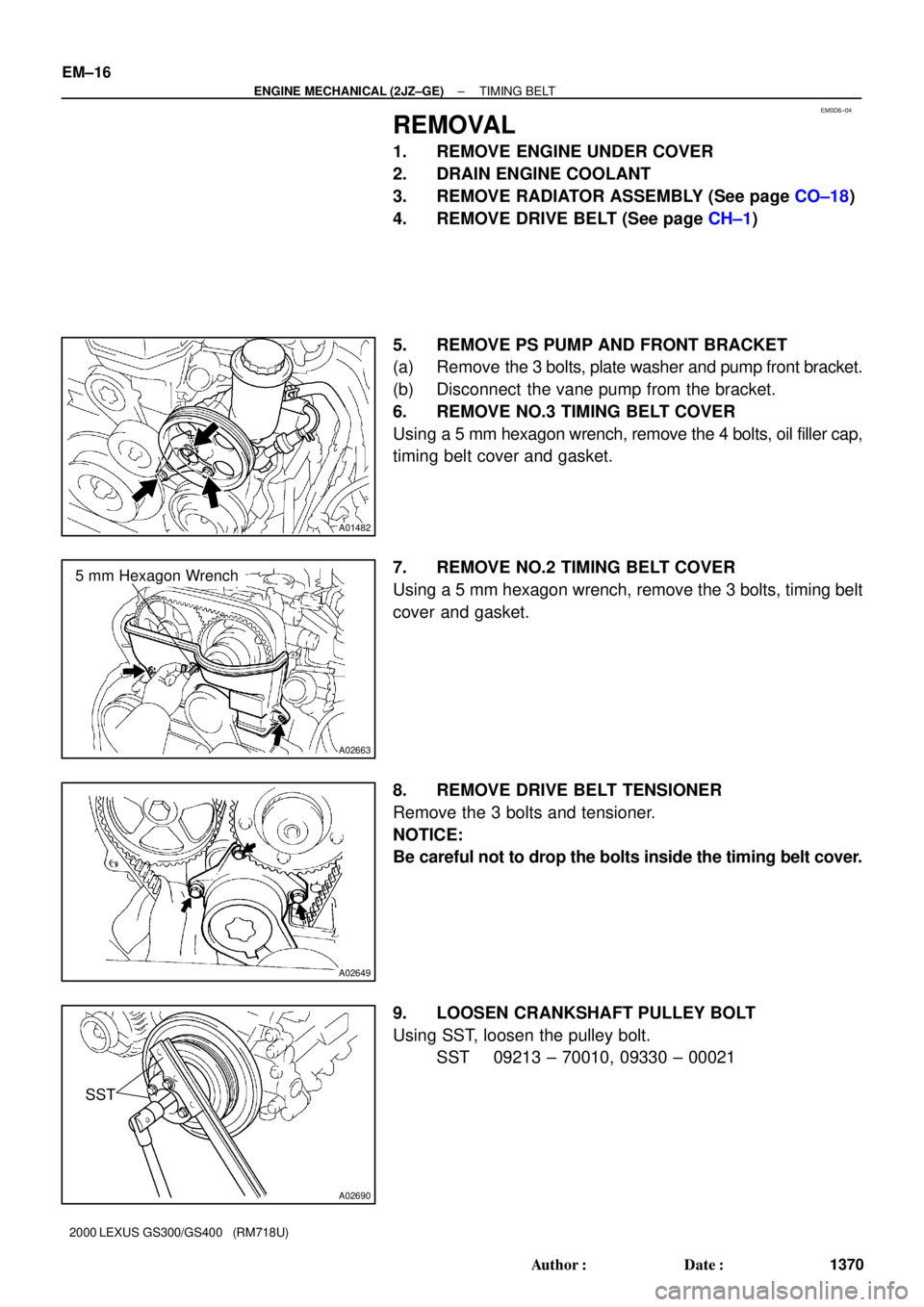
REMOVAL
1. REMOVE ENGINE UNDER COVER
2. DRAIN ENGINE COOLANT
3. REMOVE RADIATOR ASSEMBLY (See page CO±18)
4. REMOVE DRIVE BELT (See page CH±1)
5. REMOVE PS PUMP AND FRONT BRACKET
(a) Remove the 3 bolts, plate washer and pump front bracket.
(b) Disconnect the vane pump from the bracket.
6. REMOVE NO.3 TIMING BELT COVER
Using a 5 mm hexagon wrench, remove the 4 bolts, oil filler cap,
timing belt cover and gasket.
7. REMOVE NO.2 TIMING BELT COVER
Using a 5 mm hexagon wrench, remove the 3 bolts, timing belt
cover and gasket.
8. REMOVE DRIVE BELT TENSIONER
Remove the 3 bolts and tensioner.
NOTICE:
Be careful not to drop the bolts inside the timing belt cover.
9. LOOSEN CRANKSHAFT PULLEY BOLT
Using SST, loosen the pulley bolt.
SST 09213 ± 70010, 09330 ± 00021
Page 520 of 1111
TIMING BELT
EM±17
1371 Author�: Date�:
2000 LEXUS GS300")
A02656
A02671
Timing MarkSub Timing Mark
60°
Turn
A02660
Dot
Mark
30°Timing
MarkDot
Mark
30°Timing
Mark
A02653
± ENGINE MECHANICAL (2JZ±GE)TIMING BELT
EM±17
1371 Author�: Date�:
2000 LEXUS GS300/GS400 (RM718U)
10. SET NO.1 CYLINDER TO APPROX. 60°/ BTDC COM-
PRESSION
(a) Turn the crankshaft pulley, and align its groove with timing
mark º0º of the No.1 timing belt cover.
NOTICE:
Always turn the crankshaft clockwise.
(b) Check that the timing marks (TDC mark) of the camshaft
timing pulleys are aligned with the timing marks of the
No.4 timing belt cover.
If not, turn the crankshaft 1 revolution (360°).
(c) Turn the crankshaft pulley 60° counterclockwise to place
the sub timing mark (60° mark BTDC) on the crankshaft
pulley at the timing mark º0º position of the No.1 timing
belt cover.
NOTICE:
If the timing belt is disengaged, having the crankshaft
pulley at the wrong angle can cause the piston head and
valve head to come into contact with each other when you
remove the camshaft timing pulleys (steps 11 to 17), thus
resulting damage. So, always set the crankshaft pulley at
the correct angle.
(d) Check that the dot marks (60° mark BTDC) of the cam-
shaft timing pulleys are aligned with the timing marks of
the No.4 timing belt cover.
(e) Remove the crankshaft pulley bolt.
NOTICE:
Do not turn the crankshaft pulley.
11. REMOVE TIMING BELT FROM CAMSHAFT TIMING
PULLEYS
HINT:
(Re±using timing belt):
Place matchmarks on the timing belt and camshaft timing pul-
leys as shown in the illustration.
Page 521 of 1111
TIMING BELT
1372 Author�: Date�:
2000 LEXUS GS300/GS400 (RM718U)
(")
P11002
A11127
SST
A11126
5 mm
Hexagon
Wrench
A02662
Gasket
Union Bolt
Oil Control
Valve Filter
EM±18
± ENGINE MECHANICAL (2JZ±GE)TIMING BELT
1372 Author�: Date�:
2000 LEXUS GS300/GS400 (RM718U)
(a) Alternately loosen the 2 bolts, and remove them, the ten-
sioner and dust boot.
(b) Disconnect the timing belt from the camshaft timing pul-
leys.
12. REMOVE EXHAUST CAMSHAFT TIMING PULLEY
Using SST, remove the bolt and timing pulley.
SST 09960±10010 (09962±01000, 09963±01000)
13. REMOVE ENGINE COVER
Remove the 4 nuts and engine cover.
14. REMOVE THROTTLE BODY AND INTAKE AIR
CONNECTOR ASSEMBLY (See page EM±5)
15. REMOVE NO.1 CYLINDER HEAD COVER
(a) Using a 5 mm hexagon wrench, remove the bolts, and dis-
connect the engine wire protector from the No.2 cylinder
head cover.
(b) Remove the nut, and disconnect the engine wire protec-
tor from the intake manifold.
(c) Remove the 2 bolts, and disconnect the high±tension
cords with the clamp from the No.2 cylinder head.
(d) Remove the 6 bolts, 2 nuts, No.1 cylinder head cover and
gasket.
16. REMOVE CAMSHAFT TIMING OIL CONTROL VALVE
(See page SF±43)
17. DISCONNECT NO.1 OIL PIPE
Remove the bolt, union bolt, oil control valve filter and 2 gas-
kets, and disconnect the No.1 oil pipe from the No.3 camshaft
bearing cap.
Page 522 of 1111

DO NOT
REMOVE
A02650
Hold
Straight
Screw
PlugSet Bolt
Seal Washer
Hexagon Wrench
A02745
SST
Bolt
± ENGINE MECHANICAL (2JZ±GE)TIMING BELT
EM±19
1373 Author�: Date�:
2")
A02655
Drain Hole
Rotate
(30°)
DO NOT
REMOVE
A02650
Hold
Straight
Screw
PlugSet Bolt
Seal Washer
Hexagon Wrench
A02745
SST
Bolt
± ENGINE MECHANICAL (2JZ±GE)TIMING BELT
EM±19
1373 Author�: Date�:
2000 LEXUS GS300/GS400 (RM718U)
18. REMOVE VVT±i (INTAKE CAMSHAFT TIMING)
PULLEY
NOTICE:
�The 5 bolts shown in the illustration determine the
backlash of the gear in the timing pulley, so do not re-
move them.
If any of the 5 bolts are removed, install a new cam-
shaft timing pulley assembly.
�When removing the straight screw plug, follow the
prescribed procedure in order to avoid spilling oil on
the timing system parts.
(a) Rotate the VVT±i pulley from left to right 2 to 3 times within
its range of movement (30°) and use a waste cloth to col-
lect the oil from the camshaft timing oil control valve instal-
lation hole.
NOTICE:
Approximately 20 cc (1.2 cu in.) of oil will be ejected, so
take care not to spill it.
(b) Holding the hexagon portion of camshaft with a wrench.
(c) Using a 14 mm hexagon wrench, remove the straight
screw plug and seal washer.
NOTICE:
Some oil may spill, so put a waster cloth below the plug
white doing the operation.
(d) Using a 10 mm hexagon wrench, and remove the set bolt
and VVT±i pulley.
(e) Remove the wrench.
19. REMOVE CRANKSHAFT PULLEY
Using SST and bolt (diameter: 8 mm, pitch: 1.5 mm), remove
the crankshaft pulley.
SST 09950±50012 (09951±05010, 09552±05010,
09553±05020, 09554±05030)
Bolt: Part No. 90119±18001
NOTICE:
Do not turn the crankshaft pulley.
20. REMOVE NO.1 TIMING BELT COVER
Remove the 5 bolts, timing belt cover and gasket.
21. REMOVE TIMING BELT GUIDE