Page 824 of 1111
SF151±01
B08999
N´m (kgf´cm, ft´lbf) : Specified torque
� Non±reusable part
21 (210, 15)
21 (210, 15)
VSV Connector for EVAP
Camshaft Position Sensor Connector
No.2 Vacuum Pipe
Accelerator Cable
EVAP Hose
Noise Filter
Connector
Vacuum
Hose
Throttle Position
Sensor Connector
� Gasket
PS Air Hose
Engine Wire Clamp
� Gasket
Oil Dipstick and
Guide for A/T
Engine Wire
Clamp
42 (420, 31)
Fuel Pressure Pulsation Damper
� Gasket
� O±Ring
Fuel Inlet Pipe Delivery Pipe
21 (210, 15)
Spacer
Injector Connector� O±Ring� O±Ring
Injector
� Insulator
� Grommet
28 (280, 21)
Engine Cover
SF±20
± SFI (2JZ±GE)INJECTOR
1486 Author�: Date�:
2000 LEXUS GS300/GS400 (RM718U)
COMPONENTS
Page 825 of 1111
SF0NB±04
B01579
± SFI (2JZ±GE)INJECTOR
SF±21
1487 Author�: Date�:
2000 LEXUS GS300/GS400 (RM718U)
REMOVAL
1. REMOVE ENGINE COVER
Remove the 4 nuts and engine cover.
2. REMOVE AIR INTAKE CHAMBER (See page SF±46)
3. REMOVE FUEL PRESSURE PULSATION DAMPER
(See page SF±26)
4. REMOVE DELIVERY PIPE AND INJECTORS
NOTICE:
�Be careful not to drop the injectors when removing
the delivery pipe.
�Pay attention to put any hung load on the injector to
and from the side direction.
(a) Disconnect the 6 injector connectors.
(b) Disconnect the camshaft position sensor connector.
(c) Disconnect the throttle position sensor connector.
(d) Disconnect the VSV connector for EVAP.
(e) Remove the 3 bolts and delivery pipe together with the 6
injectors.
(f) Pull out the 6 injectors from the delivery pipe.
(g) Remove the O±rings, grommet and insulator from each
injector.
(h) Remove the 3 spacers from the intake manifold.
Page 828 of 1111

SF0ND±04
B01220
New Insulator
New O±Ring
New Grommet New O±Ring
B01571
Turn
Outward
Connector
B01580
RotateUpward SF±24
± SFI (2JZ±GE)INJECTOR
1490 Author�: Date�:
2000 LEXUS GS300/GS400 (RM718U)
INSTALLATION
1. INSTALL INJECTORS AND DELIVERY PIPE
(a) Install new insulator and grommet to each injector.
(b) Apply a light coat of spindle oil or gasoline to 2 new O±
rings and install them to each injector.
(c) Apply a light coat of spindle oil or gasoline on the place
where a delivery pipe touches an O±ring of the injector.
(d) While turning the injector clockwise and counterclock-
wise, push it to the delivery pipe. Install the 6 injectors.
(e) Position the injector connector outward.
(f) Place the 3 spacers in position on the intake manifold.
(g) Apply a light coat of spindle oil or gasoline on the place
where a intake manifold touches an O±ring of the injector.
(h) Place the 6 injectors together with the delivery pipe and
3 bolts in position on the intake manifold.
(i) Temporarily install the 3 bolts holding the delivery pipe to
the intake manifold.
(j) Check that the injectors rotate smoothly.
HINT:
If injectors do not rotate smoothly, the probable cause is incor-
rect installation of O±rings. Replace the O±rings.
(k) Position the injector connector upward.
(l) Connect the 6 injector connectors.
HINT:
The Nos.1, 3, 5 injector connectors and dark gray, and the
Nos.2, 4, 6 injector connectors are brown.
(m) Tighten the 3 bolts holding the delivery pipe to the intake
manifold.
Torque: 21 N´m (210 kgf´cm, 15 ft´lbf)
(n) Connect the camshaft position sensor connector.
(o) Connect the throttle position sensor connector.
(p) Connect the VSV connector for EVAP.
2. INSTALL FUEL PRESSURE PULSATION DAMPER
(See page SF±27)
3. INSTALL AIR INTAKE CHAMBER
(See page SF±49)
4. INSTALL ENGINE COVER
Install the engine cover with the 4 nuts.
Page 829 of 1111
SF0NE±05
B08978
N´m (kgf´cm, ft´lbf) : Specified torque
� Non±reusable partVSV Connector for EVAP
Cover
EVAP Hose
EVAP Pipe
32 .5 (325, 24)
Fuel Pressure
Pulsation Damper
Vacuum Hose
� Gasket
Fuel Inlet Pipe
No.2 Vacuum Pipe
Engine Cover
± SFI (2JZ±GE)FUEL PRESSURE PULSATION DAMPER
SF±25
1491 Author�: Date�:
2000 LEXUS GS300/GS400 (RM718U)
FUEL PRESSURE PULSATION DAMPER
COMPONENTS
Page 830 of 1111
SF0NF±03
B09504
B01582
B09505
SST
SF±26
± SFI (2JZ±GE)FUEL PRESSURE PULSATION DAMPER
1492 Author�: Date�:
2000 LEXUS GS300/GS400 (RM718U)
REMOVAL
1. REMOVE ENGINE COVER
Remove the 4 nuts and engine cover.
2. DISCONNECT CONNECTOR AND HOSES
(a) Disconnect the VSV connector for the EVAP.
(b) Disconnect the EVAP hose from the EVAP pipe.
(c) Disconnect the vacuum hose (from No.2 vacuum pipe)
from the air intake chamber.
3. REMOVE FUEL PRESSURE PULSATION DAMPER
(a) Remove the nut holding the No.2 vacuum pipe to the in-
take manifold.
(b) Remove the bolt holding the fuel inlet pipe to the intake
manifold.
(c) Using SST, remove the pulsation damper and 2 gaskets.
SST 09612±24014 (09617±24011)
CAUTION:
�Put a shop towel under the delivery pipe.
�Slowly loosen the pulsation damper.
Page 831 of 1111

SF0NG±04
B02000
New Gasket
(Large)
(Small)
New Gasket
B01582
B09504
± SFI (2JZ±GE)FUEL PRESSURE PULSATION DAMPER
SF±27
1493 Author�: Date�:
2000 LEXUS GS300/GS400 (RM718U)
INSTALLATION
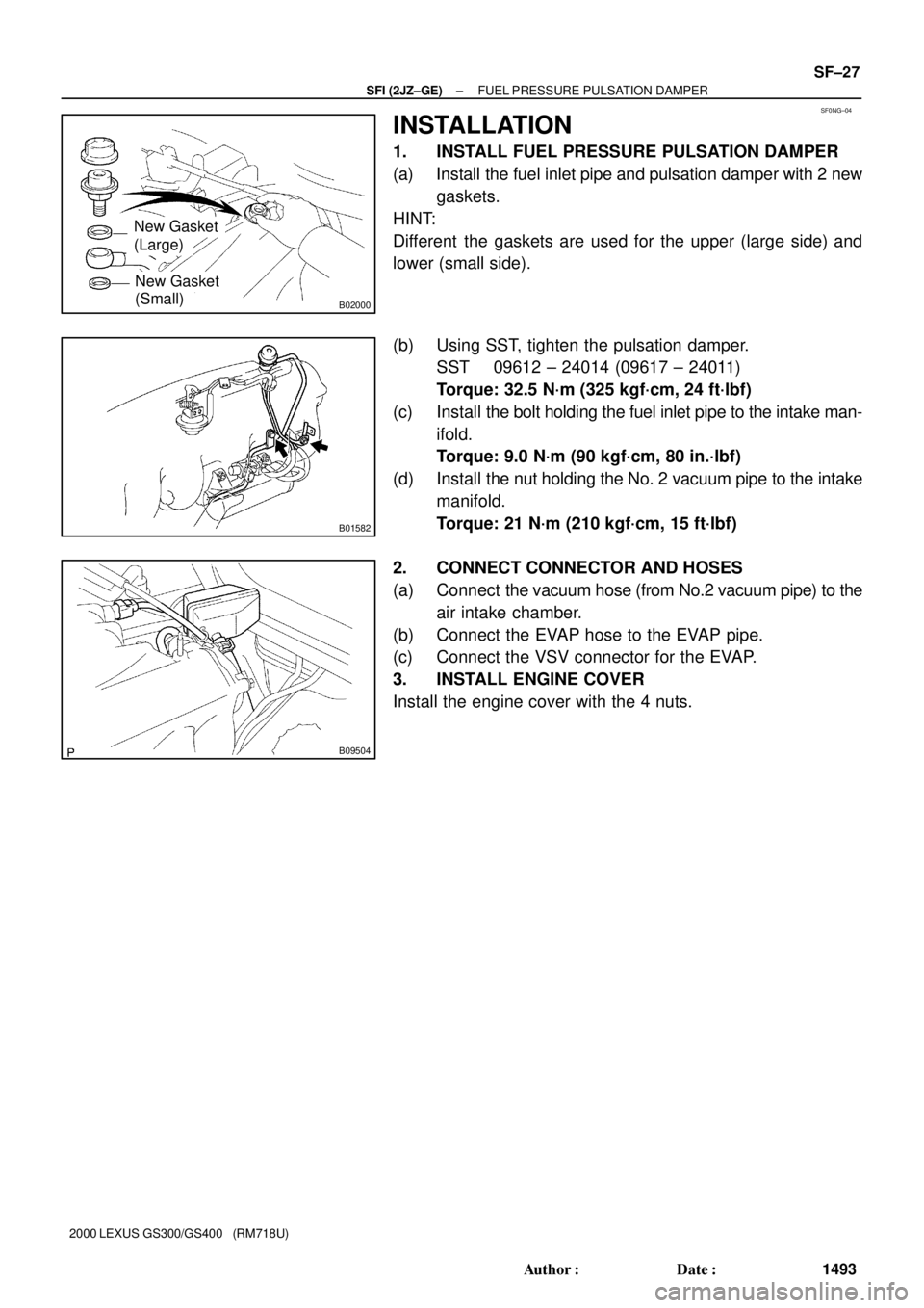
1. INSTALL FUEL PRESSURE PULSATION DAMPER
(a) Install the fuel inlet pipe and pulsation damper with 2 new
gaskets.
HINT:
Different the gaskets are used for the upper (large side) and
lower (small side).
(b) Using SST, tighten the pulsation damper.
SST 09612 ± 24014 (09617 ± 24011)
Torque: 32.5 N´m (325 kgf´cm, 24 ft´lbf)
(c) Install the bolt holding the fuel inlet pipe to the intake man-
ifold.
Torque: 9.0 N´m (90 kgf´cm, 80 in.´lbf)
(d) Install the nut holding the No. 2 vacuum pipe to the intake
manifold.
Torque: 21 N´m (210 kgf´cm, 15 ft´lbf)
2. CONNECT CONNECTOR AND HOSES
(a) Connect the vacuum hose (from No.2 vacuum pipe) to the
air intake chamber.
(b) Connect the EVAP hose to the EVAP pipe.
(c) Connect the VSV connector for the EVAP.
3. INSTALL ENGINE COVER
Install the engine cover with the 4 nuts.
Page 864 of 1111

B01982
LEXUS
Hand±Held
TesterSF0N2±05
B09511
Up
Screw
Pulsation Damper
B01958
Fuel Inlet Hose
A02818
SST
SST
(Union)
SST
(Adapter)
SF±6
± SFI (2JZ±GE)FUEL PUMP
1472 Author�: Date�:
2000 LEXUS GS300/GS400 (RM718U)
FUEL PUMP
ON±VEHICLE INSPECTION
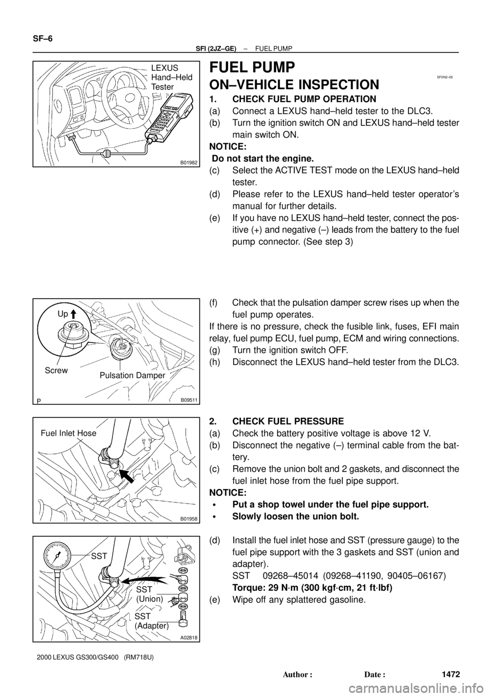
1. CHECK FUEL PUMP OPERATION
(a) Connect a LEXUS hand±held tester to the DLC3.
(b) Turn the ignition switch ON and LEXUS hand±held tester
main switch ON.
NOTICE:
Do not start the engine.
(c) Select the ACTIVE TEST mode on the LEXUS hand±held
tester.
(d) Please refer to the LEXUS hand±held tester operator's
manual for further details.
(e) If you have no LEXUS hand±held tester, connect the pos-
itive (+) and negative (±) leads from the battery to the fuel
pump connector. (See step 3)
(f) Check that the pulsation damper screw rises up when the
fuel pump operates.
If there is no pressure, check the fusible link, fuses, EFI main
relay, fuel pump ECU, fuel pump, ECM and wiring connections.
(g) Turn the ignition switch OFF.
(h) Disconnect the LEXUS hand±held tester from the DLC3.
2. CHECK FUEL PRESSURE
(a) Check the battery positive voltage is above 12 V.
(b) Disconnect the negative (±) terminal cable from the bat-
tery.
(c) Remove the union bolt and 2 gaskets, and disconnect the
fuel inlet hose from the fuel pipe support.
NOTICE:
�Put a shop towel under the fuel pipe support.
�Slowly loosen the union bolt.
(d) Install the fuel inlet hose and SST (pressure gauge) to the
fuel pipe support with the 3 gaskets and SST (union and
adapter).
SST 09268±45014 (09268±41190, 90405±06167)
Torque: 29 N´m (300 kgf´cm, 21 ft´lbf)
(e) Wipe off any splattered gasoline.
Page 865 of 1111

B01982
LEXUS
Hand±Held
Tester
B01879
Ohmmeter54
B01880
5
4 Battery
± SFI (2JZ±GE)FUEL PUMP
SF±7
1473 Author�: Date�:
2000 LEXUS GS300/GS400 (RM718U)
(f) Connect a LEXUS hand±held tester to the DLC3.
(See step 1 in check fuel pump operation (a) to (e))
(g) Measure the fuel pressure.
Fuel pressure:
304 ± 343 kPa (3.1 ± 3.5 kgf/cm
2, 44 ± 50 psi)
If pressure is high, replace the fuel pressure regulator.
If pressure is low, check the fuel hoses and connections, fuel
pump, fuel filter and fuel pressure regulator.
(h) Disconnect the LEXUS hand±held tester from the DLC3.
(i) Start the engine.
(j) Measure the fuel pressure at idle.
Fuel pressure:
304 ± 343 kPa (3.1 ± 3.5 kgf/cm
2, 44 ± 50 psi)
(k) Stop the engine.
(l) Check that the fuel pressure remains as specified for 5
minutes after the engine has stopped.
Fuel pressure: 147 kPa (1.5 kgf/cm
2, 21 psi) or more
If pressure is not as specified, check the fuel pump, pressure
regulator and/or injectors.
(m) After checking fuel pressure, disconnect the negative (±)
terminal cable from the battery and carefully remove SST
to prevent gasoline from splashing.
SST 09268±45014
(n) Reconnect the fuel inlet hose to the fuel pipe support with
2 new gaskets and the union bolt.
Torque: 29 N´m (300 kgf´cm, 21 ft´lbf)
(o) Reconnect the negative (±) terminal cable to the battery.
(p) Check for fuel leaks.
3. INSPECT FUEL PUMP
(a) Remove the rear seat cushion.
(b) Remove the 3 cap nuts and floor service hole cover.
(c) Disconnect the fuel pump & sender gauge connector.
(d) Using an ohmmeter, measure the resistance between ter-
minals 4 and 5.
Resistance: 0.2 ± 3.0 W at 20°C (68°F)
If the resistance is not as specified, replace the fuel pump.
(e) Inspect the fuel pump operation.
Connect the positive (+) lead from the battery to terminal
4 of the connector, and the negative (±) lead to terminal
5. Check that the fuel pump operates.
NOTICE:
�These tests must be done quickly (within 10 seconds)
to prevent the coil burning out.
�Keep the fuel pump as far away from the battery as
possible.
�Always do the switching at the battery side.