Page 47 of 1111
AC22B±01
I09253
I09252I10327
� O±Ring Liquid TubeDischarge Hose
N´m (kgf´cm, ft´lbf) : Specified torque
� Non±reusable partAir Cleaner Assembly
Air Cleaner Duct Condenser
Bracket
Condenser
Dryer
Filter
Cap� O±Ring
10 (100, 7)
10 (100, 7)
12.3 (125, 9)
Compressor oil ND±OIL 8 or equivalent
Radiator Upper Support
± AIR CONDITIONINGCONDENSER
AC±47
2732 Author�: Date�:
2000 LEXUS GS300/GS400 (RM718U)
COMPONENTS
Page 49 of 1111
AC22C±01
I10090
10 mm (0.39 in.)
Hexagon
Wrench
Modulator
I10092
I10093
2 Layered
Part
I10091
Protrusion
I10094
± AIR CONDITIONINGCONDENSER
AC±49
2734 Author�: Date�:
2000 LEXUS GS300/GS400 (RM718U)
REPLACEMENT
REPLACE DRYER FROM MODULATOR
(a) Using a hexagon wrench (10 mm, 0.39 in.), remove the
cap from the modulator.
(b) Remove the filter from the modulator.
(c) Using pliers, remove the dryer.
(d) Insert a new dryer into the modulator.
NOTICE:
�Do not remove the dryer from a vinyl bag until insert-
ing it into the modulator.
�Install the dryer with its 2 layered part faced upward
to the modulator.
(e) Insert the filter into the modulator.
NOTICE:
Install the filter with its protrusion faced downward to the
modulator.
(f) Install the cap to the modulator.
(1) Apply compressor oil to the o±rings and screw part
of the cap.
Compressor oil: ND±OIL 8 or equivalent
(2) Using a hexagon wrench (10 mm, 0.39 in.), install
the caps.
Torque: 12.3 N´m (125 kgf´cm, 9 ft´lbf)
Page 241 of 1111

6RadioPOOR RECEPTION
Is the condition bad in comparison with other vehicles?
Are there any additional installation parts?
(Sun shade film, telephone antenna, etc.)
Check if there is any scratch and breaking of a wire on
the glass antenna and the defogger pattern.
(visual check. tester)
(See page
BE±190)
Is the contact of the plug jack of the radio OK?
Does the condition get better by using the outer
antenna (such as pillar antenna)?
Is the contact of the antenna terminal on the glass
surface and the defogger terminal?
Is the continuity of the antenna cord OK?
Check the grounding of the antenna, antenna cord,
choke coil, and noise filter. (See page BE±190)
Does the condition get better by replacing
the choke coil?
Does the condition get better by replacing the
antenna cord?Take a measure for contact. An electric wave environment is bad.
Does the condition get better if
removing them?
Influence of additional installation parts.
Repair. (See page BE±108)
Check the radio.
Take a measure for contact.
Grounding failure. Replace the antenna cord.
Replace the choke coil.
Replace the antenna cord. Ye s
No
Exchange the glass.Ye s
Ye s
Ye s
Ye s
Ye s
Ye s
Ye s
Ye s No
No
No
NoNo
No
No
No
NG
OK
Ye s BE±202
± BODY ELECTRICALAUDIO SYSTEM
2503 Author�: Date�:
2000 LEXUS GS300/GS400 (RM718U)
Page 253 of 1111

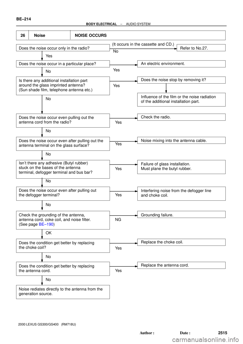
26 Noise NOISE OCCURS
No
Ye s
NG
OK Does the noise occur only in the radio?
Does the noise occur in a particular place?
Is there any additional installation part
around the glass imprinted antenna?
(Sun shade film, telephone antenna etc.)
Does the noise occur even pulling out the
antenna cord from the radio?
Does the noise occur even after pulling out the
antenna terminal on the glass surface?
Isn't there any adhesive (Butyl rubber)
stuck on the bases of the antenna
terminal, defogger terminal and bus bar?
Check the grounding of the antenna,
antenna cord, coke coil, and noise filter.
(See page BE±190) Does the noise occur even after pulling out
the defogger terminal?
Does the condition get better by replacing
the antenna cord.
Noise rediates directly to the antenna from the
generation source. Does the condition get better by replacing
the choke coil?
Replace the antenna cord. Replace the choke coil. Interfering noise from the defogger line
and choke coil.
Grounding failure. Failure of glass installation.
Must plane the butyl rubber. Noise mixing into the antenna cable. Check the radio. Influence of the film or the noise radiation
of the additional installation part. Does the noise stop by removing it? An electric environment.Refer to No.27. (It occurs in the cassette and CD.)
Ye s
Ye s
Ye s
Ye s
Ye s
Ye s
Ye s
Ye s No
No
No
No
No
No
No
No
BE±214
± BODY ELECTRICALAUDIO SYSTEM
2515 Author�: Date�:
2000 LEXUS GS300/GS400 (RM718U)
Page 518 of 1111

A11128
Accelerator Pedal Position Sensor Connector
Throttle Control Motor Connector
Throttle Body and Intake Air Connector Assembly
Water Bypass HoseVSV Connector
for EVAP
EVAP Hose
� Gasket Air Assist Hose Engine Wire
Oil Filler Cap
No.3 Timing Belt Cover
Gasket
No.2 Timing Belt Cover
GasketThrottle
Position
Sensor
Connector
Vacuum Hose
(from Actuator for ACIS)
Water Bypass Hose
Engine Wire Protector
High±Tension
Cord w/ Clamp
No.1 Cylinder
Head Cover
Gasket
Timing Belt
x 6
Timing Belt Guide
Gasket
x 5 No.1 Timing Belt Cover
Crankshaft
Pulley
21 (210, 15)
Drive Belt Tensioner
330 (3,300, 243)
Camshaft
Timing Pulley
(VVT±i Pulley)81 (810, 60)
Straight
Screw Plug
15 (150, 11)Seal Washer
Camshaft
Timing Oil
Control Valve
Camshaft Timing
Oil Control
Valve Connector� Gasket
Oil Control Valve Filter
� O±Ring
No.1 Oil PipeUnion Bolt
55 (550, 41)
Idler Pulley
Crankshaft Timing Pulley
Timing Belt Plate
Timing Belt Tensioner
N´m (kgf´cm, ft´lbf) : Specified torque
35 (350, 26)�
8.0 (80, 71 in.´lbf)
27 (270, 20)
� Non±reusable part
� Precoated part
Dust Boot
Engine Wire ClampPCV Hose
Vacuum Hose
(from No.2
Vacuum Pipe)
± ENGINE MECHANICAL (2JZ±GE)TIMING BELT
EM±15
1369 Author�: Date�:
2000 LEXUS GS300/GS400 (RM718U)
Page 521 of 1111

P11002
A11127
SST
A11126
5 mm
Hexagon
Wrench
A02662
Gasket
Union Bolt
Oil Control
Valve Filter
EM±18
± ENGINE MECHANICAL (2JZ±GE)TIMING BELT
1372 Author�: Date�:
2000 LEXUS GS300/GS400 (RM718U)
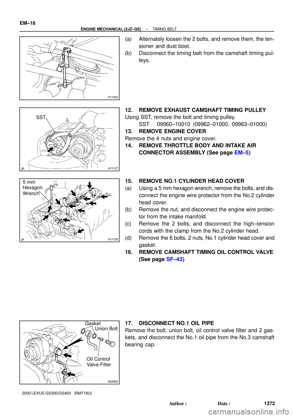
(a) Alternately loosen the 2 bolts, and remove them, the ten-
sioner and dust boot.
(b) Disconnect the timing belt from the camshaft timing pul-
leys.
12. REMOVE EXHAUST CAMSHAFT TIMING PULLEY
Using SST, remove the bolt and timing pulley.
SST 09960±10010 (09962±01000, 09963±01000)
13. REMOVE ENGINE COVER
Remove the 4 nuts and engine cover.
14. REMOVE THROTTLE BODY AND INTAKE AIR
CONNECTOR ASSEMBLY (See page EM±5)
15. REMOVE NO.1 CYLINDER HEAD COVER
(a) Using a 5 mm hexagon wrench, remove the bolts, and dis-
connect the engine wire protector from the No.2 cylinder
head cover.
(b) Remove the nut, and disconnect the engine wire protec-
tor from the intake manifold.
(c) Remove the 2 bolts, and disconnect the high±tension
cords with the clamp from the No.2 cylinder head.
(d) Remove the 6 bolts, 2 nuts, No.1 cylinder head cover and
gasket.
16. REMOVE CAMSHAFT TIMING OIL CONTROL VALVE
(See page SF±43)
17. DISCONNECT NO.1 OIL PIPE
Remove the bolt, union bolt, oil control valve filter and 2 gas-
kets, and disconnect the No.1 oil pipe from the No.3 camshaft
bearing cap.
Page 528 of 1111

A02726
Seal WasherSet BoltHold
Straight
Screw
Plug
A02722
Mesh Part
Frame Part
A11126
5 mm
Hexagon
Wrench
A02661
Front MarkSST
± ENGINE MECHANICAL (2JZ±GE)TIMING BELT
EM±25
1379 Author�: Date�:
2000 LEXUS GS300/GS400 (RM718U)
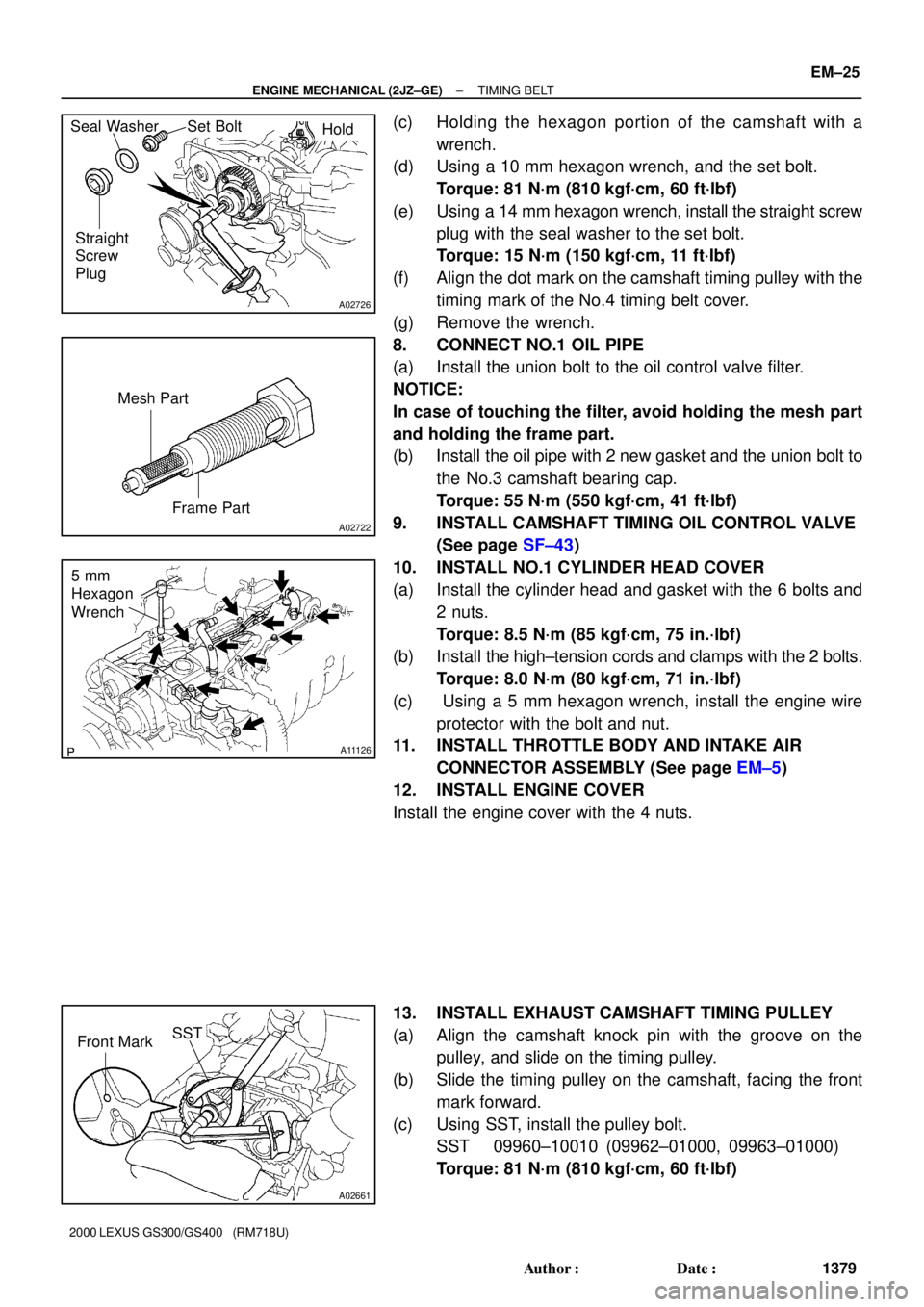
(c) Holding the hexagon portion of the camshaft with a
wrench.
(d) Using a 10 mm hexagon wrench, and the set bolt.
Torque: 81 N´m (810 kgf´cm, 60 ft´lbf)
(e) Using a 14 mm hexagon wrench, install the straight screw
plug with the seal washer to the set bolt.
Torque: 15 N´m (150 kgf´cm, 11 ft´lbf)
(f) Align the dot mark on the camshaft timing pulley with the
timing mark of the No.4 timing belt cover.
(g) Remove the wrench.
8. CONNECT NO.1 OIL PIPE
(a) Install the union bolt to the oil control valve filter.
NOTICE:
In case of touching the filter, avoid holding the mesh part
and holding the frame part.
(b) Install the oil pipe with 2 new gasket and the union bolt to
the No.3 camshaft bearing cap.
Torque: 55 N´m (550 kgf´cm, 41 ft´lbf)
9. INSTALL CAMSHAFT TIMING OIL CONTROL VALVE
(See page SF±43)
10. INSTALL NO.1 CYLINDER HEAD COVER
(a) Install the cylinder head and gasket with the 6 bolts and
2 nuts.
Torque: 8.5 N´m (85 kgf´cm, 75 in.´lbf)
(b) Install the high±tension cords and clamps with the 2 bolts.
Torque: 8.0 N´m (80 kgf´cm, 71 in.´lbf)
(c) Using a 5 mm hexagon wrench, install the engine wire
protector with the bolt and nut.
11. INSTALL THROTTLE BODY AND INTAKE AIR
CONNECTOR ASSEMBLY (See page EM±5)
12. INSTALL ENGINE COVER
Install the engine cover with the 4 nuts.
13. INSTALL EXHAUST CAMSHAFT TIMING PULLEY
(a) Align the camshaft knock pin with the groove on the
pulley, and slide on the timing pulley.
(b) Slide the timing pulley on the camshaft, facing the front
mark forward.
(c) Using SST, install the pulley bolt.
SST 09960±10010 (09962±01000, 09963±01000)
Torque: 81 N´m (810 kgf´cm, 60 ft´lbf)
Page 534 of 1111
A11124
Ignition Coils and
High±Tension Cord
Assembly
GasketNo.2 Cylinder Head Cover
Camshaft Timing Oil Control ValveExhaust Camshaft
No.1 Camshaft Bearing Cap
Gasket
No.1 Cylinder Head Cover
No.2 Camshaft Bearing Cap x 6
x 24 x 6
20 (200, 15)
20 (200, 15)
Intake Camshaft
� O±Ring
� GasketOil Control Valve Filter
x 14 No.3 Camshaft Bearing Cap
No.1 Oil Pipe
See page EM±52
1st 35 (350, 25)
2nd Turn 90°
3rd Turn 90°
Heater Hose
55 (550, 41)
Union Bolt
18 (180, 13)Spark Plug
� Oil Seal
No.4 Timing Belt Cover
Camshaft Timing Pulley
Cylinder Head Assembly
Intake Manifold Assembly
Manifold Stay
� Cylinder Head Gasket
� Gasket
x 7
81 (810, 60)
15 (150, 11)
8.0 (80, 71 in.´lbf)
N´m (kgf´cm, ft´lbf) : Specified torque
� Non±reusable partx 12
28 (280, 21)
Starter Wire
Straight
Screw Plug
Timing Belt
± ENGINE MECHANICAL (2JZ±GE)CYLINDER HEAD
EM±31
1385 Author�: Date�:
2000 LEXUS GS300/GS400 (RM718U)