Page 765 of 1111
29
38 (30)300
387 (310)22
28 (22)
Fuel tank vent tub")
SS0FL±05
SS±12
±
168 Author�: Date�:
TORQUE SPECIFICATION
Part tightenedN´mkgf´cmft´lbf
Fuel line for union bolt
for flare nut (for using SST)29
38 (30)300
387 (310)22
28 (22)
Fuel tank vent tube set plate x Fuel tank3.53631 in.´lbf
Fuel inlet hose x Body9.09080 in.´lbf
Delivery pipe x Intake manifold2121015
Fuel pressure pulsation damper x Fuel pipe support32.532524
Fuel inlet pipe x Intake manifold9.09080 in.´lbf
No.2 vacuum pipe x Intake manifold2121015
Fuel sender gauge x Fuel tank1.51513 in.´lbf
Fuel tank band x Body3940031
MAF meter x Air cleaner10.71098
Throttle body bracket x Throttle body2121015
Throttle body bracket x Cylinder head2121015
Throttle position sensor x Throttle body1.717.515 in.´lbf
Throttle control motor x Throttle body3.737.533 in.´lbf
Throttle control motor cover x Throttle body1.717.515 in.´lbf
Accelerator pedal position sensor x Throttle body3.737.533 in.´lbf
Camshaft timing oil control valve x No.3 camshaft bearing cap8.08071 in.´lbf
No.3 timing belt cover x Cylinder head cover8.08071 in.´lbf
Intake air connector x Air intake chamber2828021
Air intake chamber x Intake manifold2828021
Vacuum control valve set x Intake manifold2121015
ECT sensor x Cylinder head19.620014
Knock sensor x Cylinder block4445033
PS pump rear stay x Manifold stay39.240029
PS pump rear stay x PS pump bracket39.240029
Heated oxygen sensor x Exhaust manifold4545033
Heated oxygen sensor x Front exhaust pipe4545033
Page 812 of 1111
SFI SYSTEM
SF±3
1469 Author�: Date�:
2000 LEXUS GS300/GS400 (RM718U)
8. FUEL SYSTEM
(a) When")
B01875
Fuel
Pump
Connector
B01998
New
Gasket
New
Gasket
FI1654
SST
Fulcrum Length
30 cm
± SFI (2JZ±GE)SFI SYSTEM
SF±3
1469 Author�: Date�:
2000 LEXUS GS300/GS400 (RM718U)
8. FUEL SYSTEM
(a) When disconnecting the high pressure fuel line, a large
amount of gasoline will spill out, so observe these proce-
dures:
(1) Disconnect the fuel pump connector.
(2) Start the engine. After the engine has stopped on
its own, turn the ignition switch OFF.
(3) Put a container under the connection.
(4) Slowly loosen the connection.
(5) Disconnect the connection.
(6) Plug the connection with a rubber plug.
(7) Reconnect the fuel pump connector.
(b) When connecting the flare nut or union bolt on the high
pressure pipe union, observe these procedures:
(1) Union Bolt Type:
Always use a new gasket.
(2) Union Bolt Type:
Tighten the union bolt by hand.
(3) Union Bolt Type:
Tighten the union bolt to the specified torque.
Torque: 29 N´m (300 kgf´cm, 22 ft´lbf)
(4) Flare Nut Type:
Apply a light coat of engine oil to the flare and tight-
en the flare nut by hand.
(5) Flare Nut Type:
Using SST, tighten the flare nut to the specified
torque.
SST 09631±22020
NOTICE:
Do not rotate the fuel pipe, when tightening the flare nut.
Torque:
30 N´m (310 kgf´cm, 22 ft´lbf) for using SST
38 N´m (387 kgf´cm, 28 ft´lbf)
HINT:
Use a torque wrench with a fulcrum length of 30 cm (11.81 in.).
Page 815 of 1111
FUEL PUMP
SF±11
1477 Author�: Date�:
2000 LEXUS GS300/GS400 (RM718U)
REMOVAL
CAUTION:
Do not smoke or w")
SF0N4±01
B01876
B01877
Pull
Remove
Plug
B01878
B01874
Fuel
Sub Suction
Hose
± SFI (2JZ±GE)FUEL PUMP
SF±11
1477 Author�: Date�:
2000 LEXUS GS300/GS400 (RM718U)
REMOVAL
CAUTION:
Do not smoke or work near an open frame when working
the fuel pump.
1. REMOVE REAR SEAT CUSHION
2. REMOVE FLOOR SERVICE HOLE COVER
Remove the 3 cap nuts and service hole cover.
3. DISCONNECT FUEL PUMP & SENDER GAUGE CON-
NECTOR
4. DISCONNECT FUEL TANK MAIN TUBE (FUEL TUBE
CONNECTOR) FROM FUEL SECTION PLATE
CAUTION:
�Perform disconnecting operation of the fuel tube con-
nector (quick type) after observing precaution. (See
page SF±1)
�As there is retained pressure in the fuel line, prevent
it from splashing inside the vehicle compartment.
(a) Remove the tube joint clip.
(b) Pull out the fuel main tube.
(c) Plug the port of the fuel suction plate with a clean rubber
cap.
5. REMOVE FUEL PUMP AND SENDER GAUGE AS-
SEMBLY FROM FUEL TANK
(a) Remove the 8 bolts and fuel tank vent tube set plate.
(b) Lift up the fuel pump and sender gauge assembly, and
disconnect the fuel sub suction hose from the fuel return
jet tube and remove the fuel pump, sender gauge assem-
bly and gasket.
6. REMOVE NO.2 FUEL SUCTION SUPPORT
(See page SF±17)
7. REMOVE FUEL PRESSURE REGULATOR AND FUEL
RETURN JET TUBE ASSEMBLY (See page SF±17)
Page 817 of 1111
FUEL PUMP
SF±13
1479 Author�: Date�:
2000 LEXUS")
SF0N5±02
B02037
Push
B01892
Fuel Port Hole
No.1 Fuel Filter
Cushion
Fuel Port
New O±Ring
B01893
B02038
Snap Claw
Push
B01887
New Clip
± SFI (2JZ±GE)FUEL PUMP
SF±13
1479 Author�: Date�:
2000 LEXUS GS300/GS400 (RM718U)
INSTALLATION
1. INSTALL FUEL PUMP TO FUEL FILTER
Push in the fuel pump.
2. INSTALL FUEL FILTER AND FUEL PUMP ASSEMBLY
(a) Install the No.1 fuel filter cushion to the fuel suction plate.
(b) Apply a light coat of gasoline to a new O±ring and install
it to the fuel port of the fuel suction plate.
(c) Align the fuel port of the fuel suction plate with the fuel port
hole of the fuel filter.
(d) Push in the fuel filter.
(e) Connect the fuel pump connector.
3. INSTALL NO.1 FUEL SUCTION SUPPORT
(a) Install the No.2 fuel filter cushion to the fuel filter.
(b) Push the fuel suction support, and attach the 4 snap
claws to the claw holes.
4. INSTALL FUEL SUCTION FILTER
Install the suction filter with a new clip.
5. INSTALL FUEL PRESSURE REGULATOR AND FUEL
RETURN JET TUBE ASSEMBLY (See page SF±18)
6. INSTALL NO.2 FUEL SUCTION SUPPORT
(See page SF±18)
Page 819 of 1111
SF0N6±01
B01873
Rear Seat Cushion
Floor Service Hole Cover
Fuel Pump & Sender Gauge
Connector
Fuel Tank Vent Tube
Set PlateFuel Tank Main Tube
Tube Joint Clip
Fuel Pump and Sender Gauge
Assembly
Fuel Sub Suction Hose
� Non±reusable part
� Gasket
x 8
N´m (kgf´cm, ft´lbf) : Specified torque
3.5 (36, 31 in.´lbf)
± SFI (2JZ±GE)FUEL PRESSURE REGULATOR
SF±15
1481 Author�: Date�:
2000 LEXUS GS300/GS400 (RM718U)
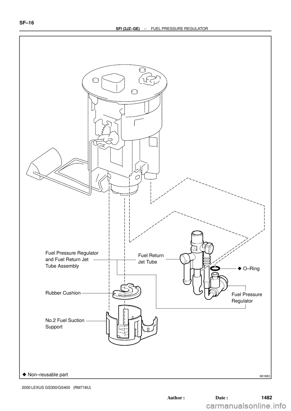
FUEL PRESSURE REGULATOR
COMPONENTS
Page 820 of 1111
B01883
Fuel Return
Jet Tube
Rubber Cushion
No.2 Fuel Suction
SupportFuel Pressure
Regulator� O±RingFuel Pressure Regulator
and Fuel Return Jet
Tube Assembly
� Non±reusable part
SF±16
± SFI (2JZ±GE)FUEL PRESSURE REGULATOR
1482 Author�: Date�:
2000 LEXUS GS300/GS400 (RM718U)
Page 821 of 1111
SF0N7±01
B01884
PrySnap ClawPry
B01886
Disconnect
Pull
± SFI (2JZ±GE)FUEL PRESSURE REGULATOR
SF±17
1483 Author�: Date�:
2000 LEXUS GS300/GS400 (RM718U)
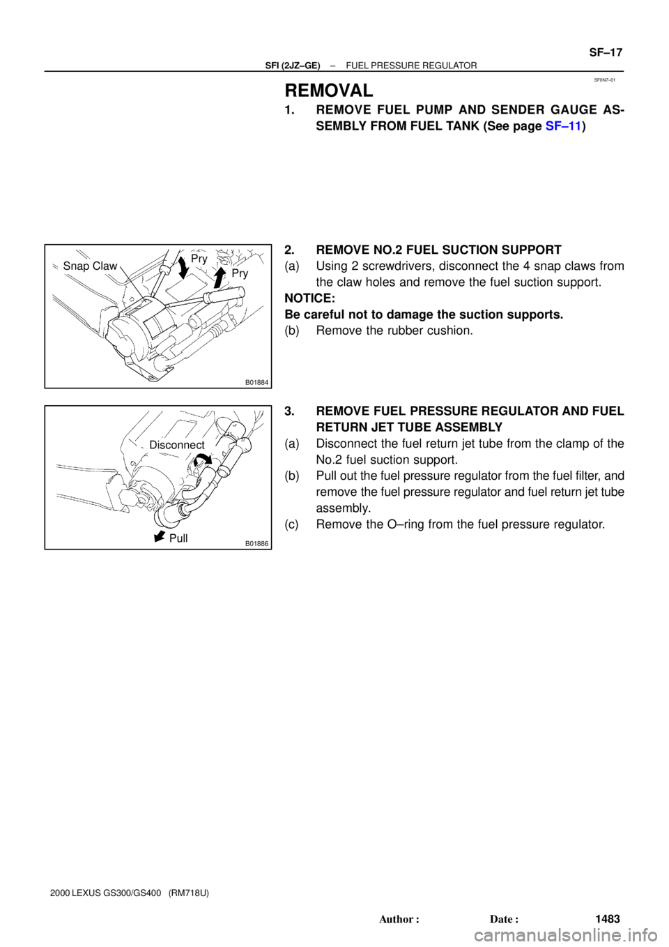
REMOVAL
1. REMOVE FUEL PUMP AND SENDER GAUGE AS-
SEMBLY FROM FUEL TANK (See page SF±11)
2. REMOVE NO.2 FUEL SUCTION SUPPORT
(a) Using 2 screwdrivers, disconnect the 4 snap claws from
the claw holes and remove the fuel suction support.
NOTICE:
Be careful not to damage the suction supports.
(b) Remove the rubber cushion.
3. REMOVE FUEL PRESSURE REGULATOR AND FUEL
RETURN JET TUBE ASSEMBLY
(a) Disconnect the fuel return jet tube from the clamp of the
No.2 fuel suction support.
(b) Pull out the fuel pressure regulator from the fuel filter, and
remove the fuel pressure regulator and fuel return jet tube
assembly.
(c) Remove the O±ring from the fuel pressure regulator.
Page 822 of 1111
SF0N8±01
B02061
Connect
Push
B01885
B02039Push
Snap Claw
SF±18
± SFI (2JZ±GE)FUEL PRESSURE REGULATOR
1484 Author�: Date�:
2000 LEXUS GS300/GS400 (RM718U)
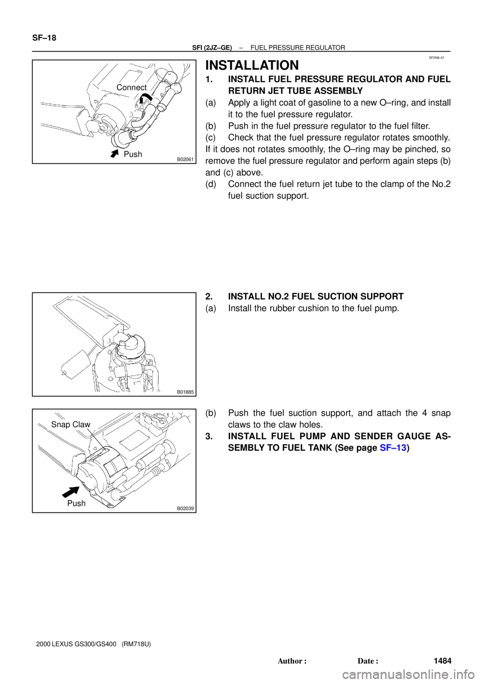
INSTALLATION
1. INSTALL FUEL PRESSURE REGULATOR AND FUEL
RETURN JET TUBE ASSEMBLY
(a) Apply a light coat of gasoline to a new O±ring, and install
it to the fuel pressure regulator.
(b) Push in the fuel pressure regulator to the fuel filter.
(c) Check that the fuel pressure regulator rotates smoothly.
If it does not rotates smoothly, the O±ring may be pinched, so
remove the fuel pressure regulator and perform again steps (b)
and (c) above.
(d) Connect the fuel return jet tube to the clamp of the No.2
fuel suction support.
2. INSTALL NO.2 FUEL SUCTION SUPPORT
(a) Install the rubber cushion to the fuel pump.
(b) Push the fuel suction support, and attach the 4 snap
claws to the claw holes.
3. INSTALL FUEL PUMP AND SENDER GAUGE AS-
SEMBLY TO FUEL TANK (See page SF±13)