2000 DODGE NEON wheel bolt torque
[x] Cancel search: wheel bolt torquePage 744 of 1285
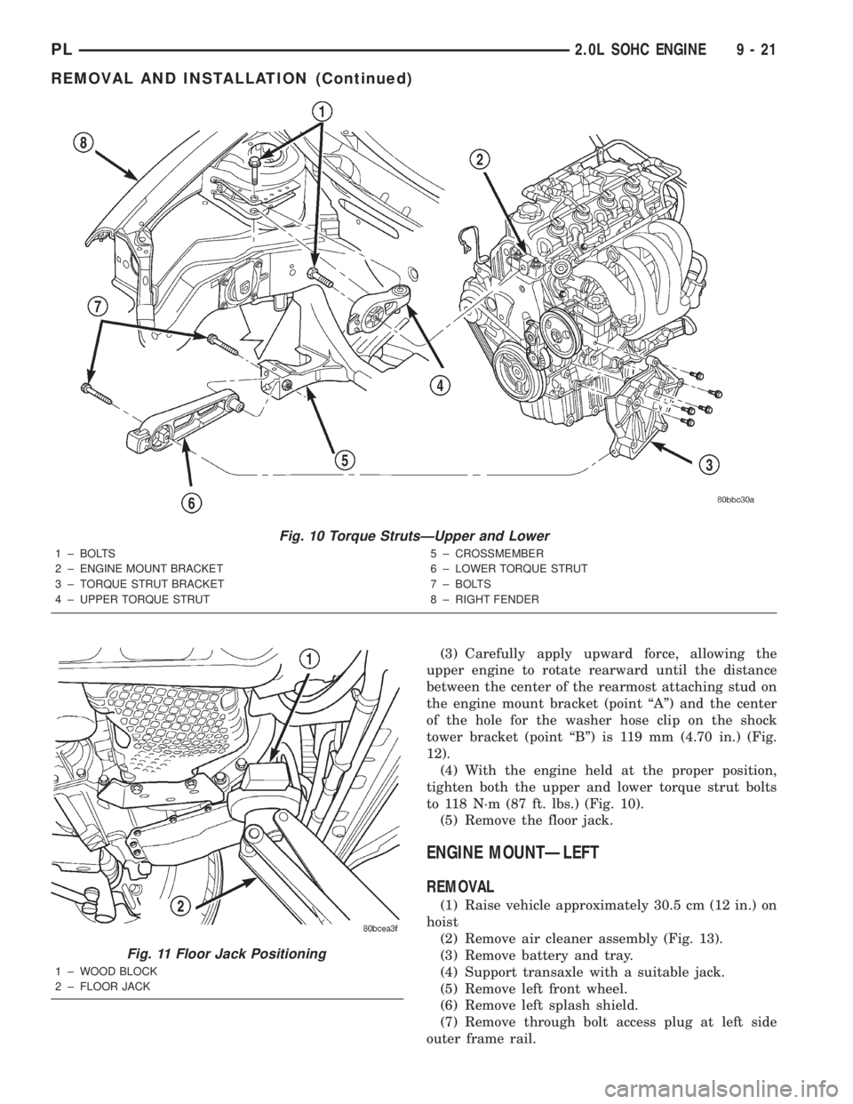
(3) Carefully apply upward force, allowing the
upper engine to rotate rearward until the distance
between the center of the rearmost attaching stud on
the engine mount bracket (point ªAº) and the center
of the hole for the washer hose clip on the shock
tower bracket (point ªBº) is 119 mm (4.70 in.) (Fig.
12).
(4) With the engine held at the proper position,
tighten both the upper and lower torque strut bolts
to 118 N´m (87 ft. lbs.) (Fig. 10).
(5) Remove the floor jack.
ENGINE MOUNTÐLEFT
REMOVAL
(1) Raise vehicle approximately 30.5 cm (12 in.) on
hoist
(2) Remove air cleaner assembly (Fig. 13).
(3) Remove battery and tray.
(4) Support transaxle with a suitable jack.
(5) Remove left front wheel.
(6) Remove left splash shield.
(7) Remove through bolt access plug at left side
outer frame rail.
Fig. 10 Torque StrutsÐUpper and Lower
1 ± BOLTS
2 ± ENGINE MOUNT BRACKET
3 ± TORQUE STRUT BRACKET
4 ± UPPER TORQUE STRUT5 ± CROSSMEMBER
6 ± LOWER TORQUE STRUT
7 ± BOLTS
8 ± RIGHT FENDER
Fig. 11 Floor Jack Positioning
1 ± WOOD BLOCK
2 ± FLOOR JACK
PL2.0L SOHC ENGINE 9 - 21
REMOVAL AND INSTALLATION (Continued)
Page 749 of 1285
(4) Discharge air conditioning system, if equipped.
Refer to Group 24, Heating and Air Conditioning for
procedure.
(5) Disconnect the following: air intake duct at
intake manifold, throttle cables, electrical connectors
from throttle body and air cleaner housing.
(6) Remove air cleaner housing assembly.
(7) Remove upper radiator hose and fan module.
Refer to Group 7, Cooling System for procedure.
(8) Remove lower radiator hose.
(9) Disconnect automatic transmission cooler lines
and plug, if equipped.
(10) Disconnect shift linkage, electrical connectors,
and clutch cable, if equipped with manual transaxle.
(11) Disconnect engine wiring harness.
(12) Disconnect positive cable from Power Distri-
bution Center (PDC) and ground wire from vehicle
body.
(13) Disconnect ground wire from the vehicle body-
to-engine at the right side strut tower.
(14) Disconnect heater hoses.
(15) Disconnect vacuum hose from brake booster.
(16) Disconnect coolant reserve/recovery hose.
(17) Remove accessory drive belts. Refer to Group
7, Cooling System for procedure.
(18) Remove power steering pump and reservoir
and set them aside.
(19) Hoist vehicle and remove right inner splash
shield.
(20) Drain engine oil.
(21) Remove front wheels.
(22) Remove axle shafts. Refer to Group 3, Differ-
ential and Driveline for procedure.
(23) Disconnect exhaust system from manifold.
(24) Disconnect the downstream oxygen sensor
connector.
(25) Remove lower engine torque strut.
(26) Remove structural collar. Refer to procedure
in this section.
(27) Lower vehicle and remove A/C compressor.
(28) Raise vehicle enough to allow engine dolly
and cradle, Special Tools 6135 and 6710 to be
installed under vehicle.
(29) Loosen engine support posts to allow move-
ment for positioning onto engine locating holes and
flange on the engine bedplate. Lower vehicle and
position cradle until the engine is resting on support
posts (Fig. 26). Tighten mounts to cradle frame. This
will keep support posts from moving when removing
or installing engine and transmission.
(30) Install safety straps around the engine to cra-
dle (Fig. 26). Tighten straps and lock them into posi-
tion.
WARNING: Safety straps MUST be used.(31) Raise vehicle enough to see if straps are tight
enough to hold cradle assembly to engine.
(32) Lower vehicle so weight of the engine and
transmission ONLY is on the cradle assembly.
(33) Remove the upper engine torque strut.
(34) Remove right and left engine and transaxle
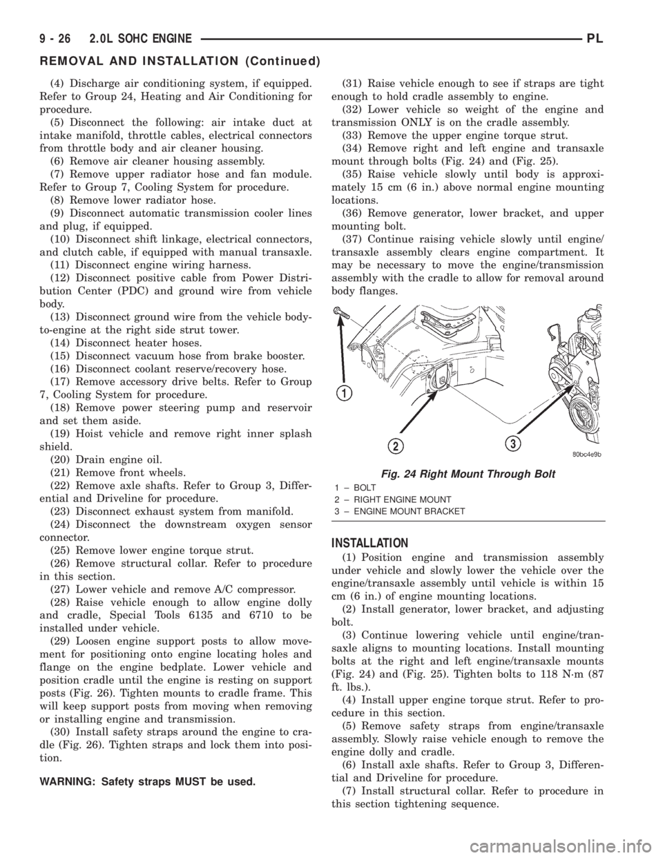
mount through bolts (Fig. 24) and (Fig. 25).
(35) Raise vehicle slowly until body is approxi-
mately 15 cm (6 in.) above normal engine mounting
locations.
(36) Remove generator, lower bracket, and upper
mounting bolt.
(37) Continue raising vehicle slowly until engine/
transaxle assembly clears engine compartment. It
may be necessary to move the engine/transmission
assembly with the cradle to allow for removal around
body flanges.
INSTALLATION
(1) Position engine and transmission assembly
under vehicle and slowly lower the vehicle over the
engine/transaxle assembly until vehicle is within 15
cm (6 in.) of engine mounting locations.
(2) Install generator, lower bracket, and adjusting
bolt.
(3) Continue lowering vehicle until engine/tran-
saxle aligns to mounting locations. Install mounting
bolts at the right and left engine/transaxle mounts
(Fig. 24) and (Fig. 25). Tighten bolts to 118 N´m (87
ft. lbs.).
(4) Install upper engine torque strut. Refer to pro-
cedure in this section.
(5) Remove safety straps from engine/transaxle
assembly. Slowly raise vehicle enough to remove the
engine dolly and cradle.
(6) Install axle shafts. Refer to Group 3, Differen-
tial and Driveline for procedure.
(7) Install structural collar. Refer to procedure in
this section tightening sequence.
Fig. 24 Right Mount Through Bolt
1 ± BOLT
2 ± RIGHT ENGINE MOUNT
3 ± ENGINE MOUNT BRACKET
9 - 26 2.0L SOHC ENGINEPL
REMOVAL AND INSTALLATION (Continued)
Page 750 of 1285
(8) Install lower engine torque strut. Refer to pro-
cedure in this section.
(9) Connect exhaust system to manifold. Refer to
Group 11, Exhaust System for procedure and torque
specifications.
(10) Connect the downstream oxygen sensor.
(11) Install A/C compressor and hoses. Refer to
Group 24, Heater and Air Conditioning for procedure.
(12) Install accessory drive belts. Refer to Group 7,
Cooling System Accessory Drive Section for belt ten-
sion adjustment.
(13) Install inner splash shield.
(14) Install wheels and lower vehicle.
(15) Install power steering pump and reservoir.
Refer to Group 7, Cooling System Accessory Drive
Section for belt tension adjustment.
(16)Manual Transmission:Connect clutch cable,
reverse light electrical connector and shift linkages.
Refer to Group 6, Clutch.
(17)Automatic Transmission:Connect shifter,
kickdown linkage and cooler lines. Refer to Group 21,
Transaxle for procedures.
(18) Connect fuel line and heater hoses.
(19)
Install all ground straps. Connect engine wiring
harness. Refer to Group 8, Electrical for procedure.
(20) Install lower radiator hose, fan module, and
upper radiator hose. Refer to Group 7, Cooling Sys-
tem for procedures
(21) Fill cooling system. Refer to Group 7, Cooling
System for filling procedure.
(22) Install battery tray and battery.
(23) Install air cleaner housing assembly and con-
nect intake duct to intake manifold.(24) Connect all throttle body electrical connectors
and linkage.
(25) Install oil filter. Fill engine crankcase with
proper oil to correct level.
(26) Perform camshaft and crankshaft timing
relearn procedure as follows:
²Connect the DRB scan tool to the data link
(diagnostic) connector. This connector is located in
the passenger compartment; at the lower edge of
instrument panel; near the steering column.
²Turn the ignition switch on and access the ªmis-
cellaneousº screen.
²Select ªre-learn cam/crankº option and follow
directions on DRB screen.
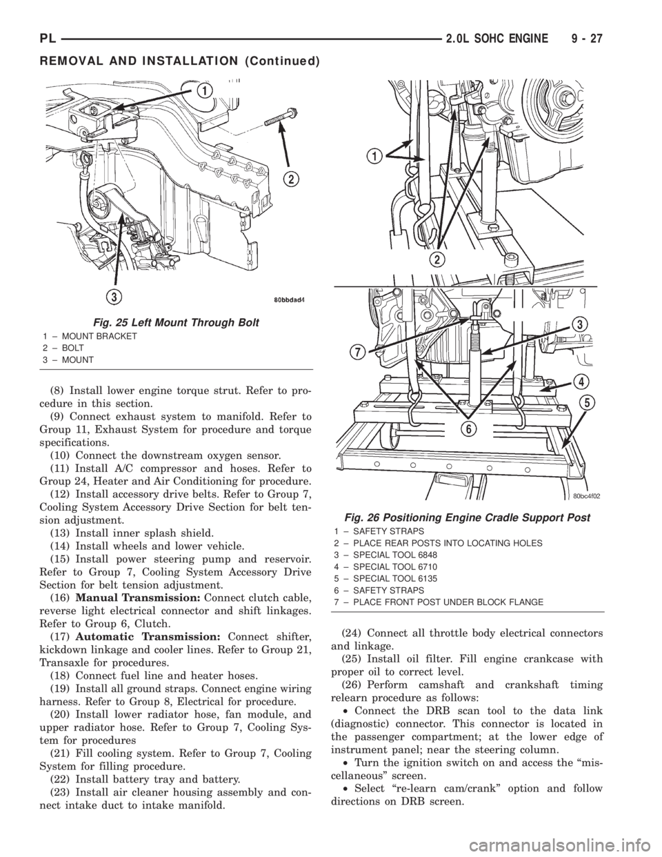
Fig. 25 Left Mount Through Bolt
1 ± MOUNT BRACKET
2 ± BOLT
3 ± MOUNT
Fig. 26 Positioning Engine Cradle Support Post
1 ± SAFETY STRAPS
2 ± PLACE REAR POSTS INTO LOCATING HOLES
3 ± SPECIAL TOOL 6848
4 ± SPECIAL TOOL 6710
5 ± SPECIAL TOOL 6135
6 ± SAFETY STRAPS
7 ± PLACE FRONT POST UNDER BLOCK FLANGE
PL2.0L SOHC ENGINE 9 - 27
REMOVAL AND INSTALLATION (Continued)
Page 760 of 1285
CYLINDER HEAD
REMOVAL
(1) Perform fuel system pressure release procedure
before attempting any repairs.Refer to Group 14,
Fuel System
(2) Disconnect negative battery cable.
(3) Remove power steering/air conditioning drive
belt. Refer to Group 7, Cooling System Accessory
Drive for procedure.
(4) Raise vehicle.
(5) Drain cooling system. Refer to Group 7, Cooling
System.
(6) Remove exhaust pipe from manifold.
(7) Remove right front wheel.
(8) Remove right side splash shield.
(9) Remove generator belt. Refer to Group 7, Cool-
ing System Accessory Drive Belts for procedure.
(10) Remove crankshaft damper. Refer to proce-
dure in this section.
(11) Remove lower torque strut.
(12) Lower vehicle and remove upper torque strut.
(13) Remove ground strap and power steering hose
support clip from engine mount bracket.
(14) Remove power steering pump assembly and
set aside.
(15) Support engine from beneath with a suitable
jack.
(16) Remove right side engine mount to bracket
through bolt.
(17) Remove the lower engine mount bracket bolt.
Raise engine slightly and remove the upper engine
mount bracket bolts.(18) Remove engine mount bracket. This procedure
may require additional raising/lowering of engine
until bracket will clear engine components.
(19) Remove front timing belt cover.
(20) Rotate engine until timing marks are aligned.
(21) Remove timing belt and tensioner. Refer to
procedures in this section.
(22) Remove camshaft sprocket. Refer to proce-
dures in this section.
(23) Remove rear timing belt cover.
(24) Disconnect fuel line at fuel rail.
(25) Remove coolant recovery container.
(26) Remove ground wire to cylinder head.
(27) Remove upper radiator hose.
(28) Remove intake manifold. Refer to procedure
in this section.
(29) Disconnect ignition coil electrical connector.
Remove coil pack and spark plug cables from engine.
(30) Remove Crankcase Closed Ventilation (CCV)
hose from cylinder head cover.
(31) Disconnect cam sensor and coolant tempera-
ture electrical connectors.
(32) Remove heater tube to cylinder head attach-
ing fasteners.
(33) Remove heater hose from thermostat housing
connector.
(34) Remove cylinder head cover.
(35) Remove cylinder head bolts.
(36) Remove cylinder head and gasket (Fig. 55).
PL2.0L SOHC ENGINE 9 - 37
REMOVAL AND INSTALLATION (Continued)
Page 763 of 1285

(13) Install ignition coil and spark plug cables.
Connect coil electrical connector.
(14) Install intake manifold. Refer to procedure in
this section.
(15) Install upper radiator hose.
(16) Install ground wire to cylinder head.
(17) Install coolant recovery container.
(18) Connect fuel line to fuel rail.
(19) Install rear timing belt cover, camshaft
sprocket, and timing belt tensioner and timing belt.
Refer to procedures in this section.
(20) Install front timing belt cover.
(21) Install engine mount bracket.
(22) Position engine and install right side engine
mount to engine mount bracket bolt. Tighten bolt to
118 N´m (87 ft. lbs.). Remove jack from beneath
engine.
(23) Install power steering pump assembly.
(24) Install power steering hose support clip and
ground strap to engine mount bracket.
(25) Install upper torque strut.
(26) Raise vehicle.
(27) Install lower torque strut.
(28) Install crankshaft damper.
(29) Install accessory drive belts. Refer to Group 7,
Cooling System Accessory Drive Belt for procedure.
(30) Install right side splash shield and front
wheel.
(31) Install exhaust pipe to exhaust manifold
flange.
(32) Lower vehicle and fill cooling system. Refer to
Group 7, Cooling System for procedure.
(33) Connect negative cable to battery.
(34) Perform camshaft and crankshaft timing
relearn procedure as follows:
²Connect the DRB scan tool to the data link
(diagnostic) connector. This connector is located in
the passenger compartment; at the lower edge of
instrument panel; near the steering column.
²Turn the ignition switch on and access the ªmis-
cellaneousº screen.
²Select ªre-learn cam/crankº option and follow
directions on DRB screen.
CRANKSHAFT DAMPER
REMOVAL
(1) Remove accessory drive belts. Refer to Group 7,
Cooling System for procedure.
(2) Raise vehicle on a hoist and remove right inner
splash shield.
(3) Remove crankshaft damper bolt. Remove
damper using the large side of Special Tool 1026 and
insert 6827-A (Fig. 61).
INSTALLATION
(1) Install crankshaft damper using M12±1.75 x
150 mm bolt, washer, thrust bearing and nut from
Special Tool 6792 (Fig. 62).
Fig. 62 Crankshaft DamperÐInstallation
1 ± M12 Ð 1.753150 MM BOLT, WASHER AND THRUST
BEARING FROM SPECIAL TOOL 6792
Fig. 60 Cylinder Head Tightening Sequence
Fig. 61 Crankshaft DamperÐRemoval
1 ± SPECIAL TOOL 6827±A INSERT
2 ± SPECIAL TOOL 1026 THREE JAW PULLER
9 - 40 2.0L SOHC ENGINEPL
REMOVAL AND INSTALLATION (Continued)
Page 775 of 1285
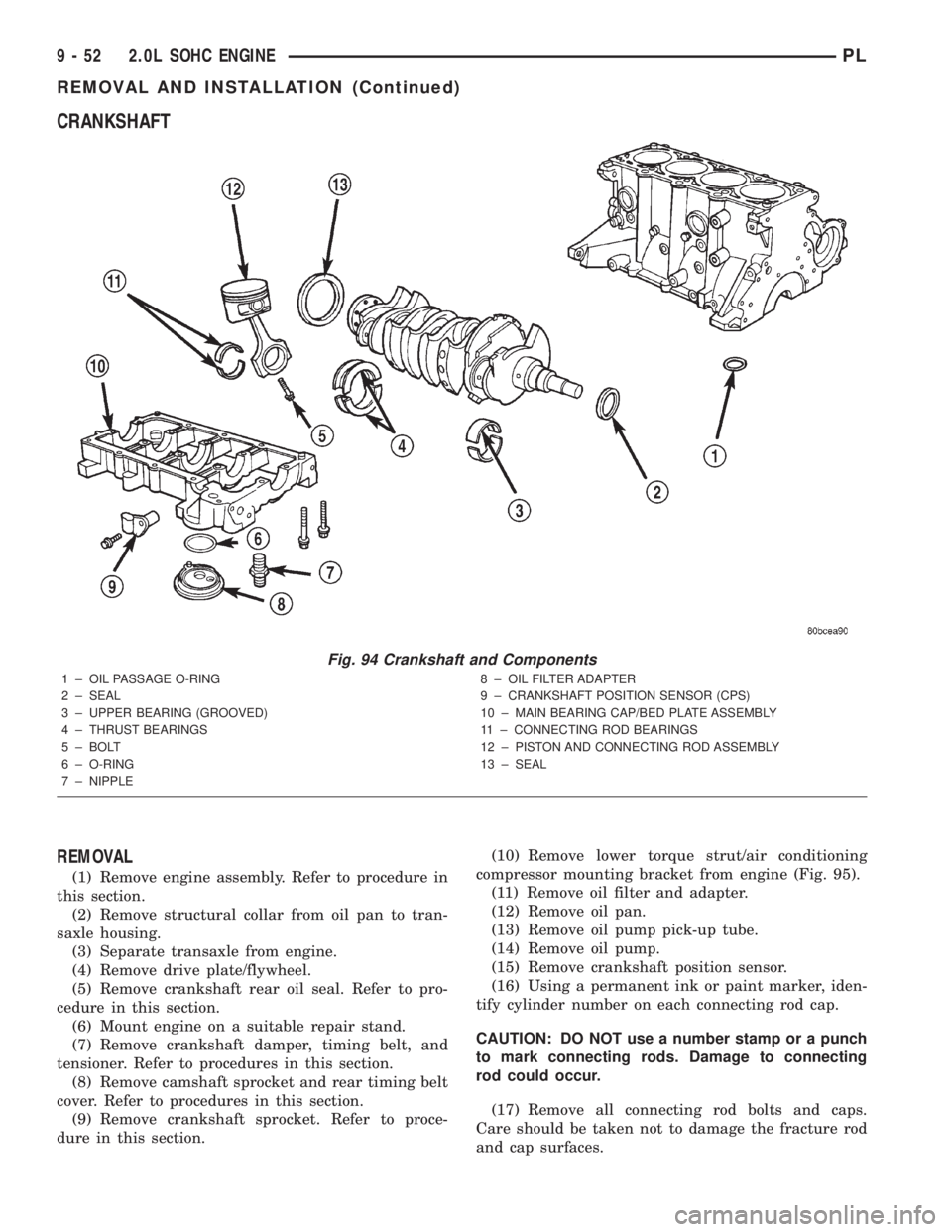
CRANKSHAFT
REMOVAL
(1) Remove engine assembly. Refer to procedure in
this section.
(2) Remove structural collar from oil pan to tran-
saxle housing.
(3) Separate transaxle from engine.
(4) Remove drive plate/flywheel.
(5) Remove crankshaft rear oil seal. Refer to pro-
cedure in this section.
(6) Mount engine on a suitable repair stand.
(7) Remove crankshaft damper, timing belt, and
tensioner. Refer to procedures in this section.
(8) Remove camshaft sprocket and rear timing belt
cover. Refer to procedures in this section.
(9) Remove crankshaft sprocket. Refer to proce-
dure in this section.(10) Remove lower torque strut/air conditioning
compressor mounting bracket from engine (Fig. 95).
(11) Remove oil filter and adapter.
(12) Remove oil pan.
(13) Remove oil pump pick-up tube.
(14) Remove oil pump.
(15) Remove crankshaft position sensor.
(16) Using a permanent ink or paint marker, iden-
tify cylinder number on each connecting rod cap.
CAUTION: DO NOT use a number stamp or a punch
to mark connecting rods. Damage to connecting
rod could occur.
(17) Remove all connecting rod bolts and caps.
Care should be taken not to damage the fracture rod
and cap surfaces.
Fig. 94 Crankshaft and Components
1 ± OIL PASSAGE O-RING
2 ± SEAL
3 ± UPPER BEARING (GROOVED)
4 ± THRUST BEARINGS
5 ± BOLT
6 ± O-RING
7 ± NIPPLE8 ± OIL FILTER ADAPTER
9 ± CRANKSHAFT POSITION SENSOR (CPS)
10 ± MAIN BEARING CAP/BED PLATE ASSEMBLY
11 ± CONNECTING ROD BEARINGS
12 ± PISTON AND CONNECTING ROD ASSEMBLY
13 ± SEAL
9 - 52 2.0L SOHC ENGINEPL
REMOVAL AND INSTALLATION (Continued)
Page 810 of 1285
FRAMES
TABLE OF CONTENTS
page page
DESCRIPTION AND OPERATION
FRONT SUSPENSION......................5
REMOVAL AND INSTALLATION
FRONT SUSPENSION CROSSMEMBER........5SPECIFICATIONS
FRAME DIMENSIONS......................9
STRUCTURAL DIMENSIONS................13
TORQUE SPECIFICATIONS.................15
DESCRIPTION AND OPERATION
FRONT SUSPENSION
The front suspension crossmember must be prop-
erly installed to achieve design camber, caster set-
tings and wheel stagger. The crossmember can be
installed out of position on the frame rails due to its
design. Bolts and cage nuts hold the rear of the
crossmember to the frame torque boxes. Bolts and
J-nuts hold the front of the crossmember to the
frame rails. No designed in locating device is used to
position the crossmember in the vehicle. Before
removing the crossmember mark the frame torque
box around the rear mounting location to aid instal-
lation. A crossmember that is removed during service
must be installed in the same position from which it
was removed. To verify that crossmember is in the
proper position, refer to the dimensions provided.
Front end dimensions are gauged from the principal
locating point (PLP) holes located under the frame
torque boxes rearward of the front wheels. After
removal and installation of the crossmember is per-
formed, verify that front suspension alignment is
within specifications. If camber, caster settings and
wheel stagger is not within specifications, loosen and
reposition crossmember to bring suspension within
specifications. Refer to Group 2, Front Suspension for
additional information.
REMOVAL AND INSTALLATION
FRONT SUSPENSION CROSSMEMBER
CAUTION: If the front suspension crossmember is
being replaced due to collision damage, inspect the
steering column lower coupling for damage. Refer
to STEERING COLUMN in the STEERING service
manual group for the procedure.
REMOVAL
(1) Raise the vehicle. Refer to HOISTING in the
LUBRICATION AND MAINTENANCE group in this
service manual for the correct lifting procedure.
(2) Remove both front tire and wheel assemblies
from the vehicle.
(3) Remove both stabilizer bar links from the vehi-
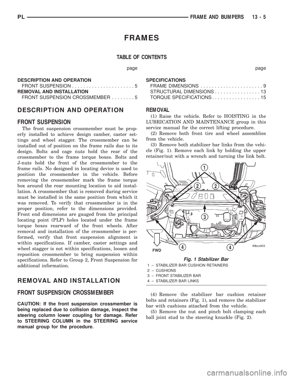
cle (Fig. 1). Remove each link by holding the upper
retainer/nut with a wrench and turning the link bolt.
(4) Remove the stabilizer bar cushion retainer
bolts and retainers (Fig. 1), and remove the stabilizer
bar with cushions attached from the vehicle.
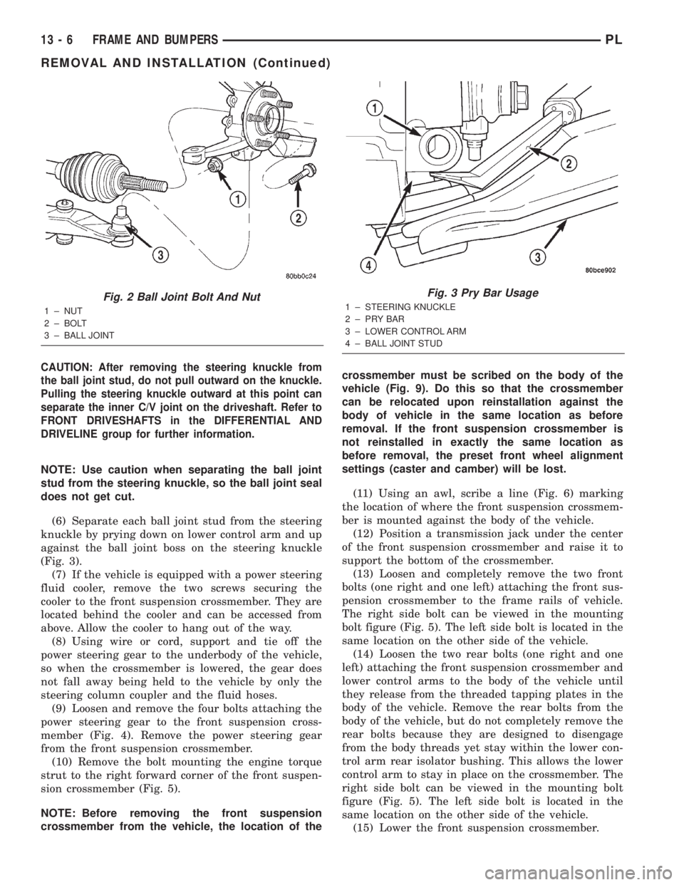
(5) Remove the nut and pinch bolt clamping each
ball joint stud to the steering knuckle (Fig. 2).
Fig. 1 Stabilizer Bar
1 ± STABILIZER BAR CUSHION RETAINERS
2 ± CUSHIONS
3 ± FRONT STABILIZER BAR
4 ± STABILIZER BAR LINKS
PLFRAME AND BUMPERS 13 - 5
Page 811 of 1285
CAUTION: After removing the steering knuckle from
the ball joint stud, do not pull outward on the knuckle.
Pulling the steering knuckle outward at this point can
separate the inner C/V joint on the driveshaft. Refer to
FRONT DRIVESHAFTS in the DIFFERENTIAL AND
DRIVELINE group for further information.
NOTE: Use caution when separating the ball joint
stud from the steering knuckle, so the ball joint seal
does not get cut.
(6) Separate each ball joint stud from the steering
knuckle by prying down on lower control arm and up
against the ball joint boss on the steering knuckle
(Fig. 3).
(7) If the vehicle is equipped with a power steering
fluid cooler, remove the two screws securing the
cooler to the front suspension crossmember. They are
located behind the cooler and can be accessed from
above. Allow the cooler to hang out of the way.
(8) Using wire or cord, support and tie off the
power steering gear to the underbody of the vehicle,
so when the crossmember is lowered, the gear does
not fall away being held to the vehicle by only the
steering column coupler and the fluid hoses.
(9) Loosen and remove the four bolts attaching the
power steering gear to the front suspension cross-
member (Fig. 4). Remove the power steering gear
from the front suspension crossmember.
(10) Remove the bolt mounting the engine torque
strut to the right forward corner of the front suspen-
sion crossmember (Fig. 5).
NOTE: Before removing the front suspension
crossmember from the vehicle, the location of thecrossmember must be scribed on the body of the
vehicle (Fig. 9). Do this so that the crossmember
can be relocated upon reinstallation against the
body of vehicle in the same location as before
removal. If the front suspension crossmember is
not reinstalled in exactly the same location as
before removal, the preset front wheel alignment
settings (caster and camber) will be lost.
(11) Using an awl, scribe a line (Fig. 6) marking
the location of where the front suspension crossmem-
ber is mounted against the body of the vehicle.
(12) Position a transmission jack under the center
of the front suspension crossmember and raise it to
support the bottom of the crossmember.
(13) Loosen and completely remove the two front
bolts (one right and one left) attaching the front sus-
pension crossmember to the frame rails of vehicle.
The right side bolt can be viewed in the mounting
bolt figure (Fig. 5). The left side bolt is located in the
same location on the other side of the vehicle.
(14) Loosen the two rear bolts (one right and one
left) attaching the front suspension crossmember and
lower control arms to the body of the vehicle until
they release from the threaded tapping plates in the
body of the vehicle. Remove the rear bolts from the
body of the vehicle, but do not completely remove the
rear bolts because they are designed to disengage
from the body threads yet stay within the lower con-
trol arm rear isolator bushing. This allows the lower
control arm to stay in place on the crossmember. The
right side bolt can be viewed in the mounting bolt
figure (Fig. 5). The left side bolt is located in the
same location on the other side of the vehicle.
(15) Lower the front suspension crossmember.
Fig. 2 Ball Joint Bolt And Nut
1 ± NUT
2 ± BOLT
3 ± BALL JOINT
Fig. 3 Pry Bar Usage
1 ± STEERING KNUCKLE
2±PRYBAR
3 ± LOWER CONTROL ARM
4 ± BALL JOINT STUD
13 - 6 FRAME AND BUMPERSPL
REMOVAL AND INSTALLATION (Continued)