2000 DODGE NEON wheel bolt torque
[x] Cancel search: wheel bolt torquePage 67 of 1285
CAUTION: The driveshaft, when installed, acts as a
bolt and secures the front hub/bearing assembly. If
vehicle is to be supported or moved on its wheels
with a driveshaft removed, install a PROPER±SIZED
BOLT AND NUT through front hub. Tighten bolt and
nut to 203 N´m (150 ft. lbs.). This will ensure that
the hub bearing cannot loosen.
INSTALLATION
(1) Thoroughly clean spline and oil seal sealing
surface, on tripod joint. Lightly lubricate oil seal
sealing surface on tripod joint with fresh clean trans-
mission lubricant.
(2) Holding driveshaft assembly by tripod joint and
interconnecting shaft, install tripod joint into tran-
saxle side gear as far as possible by hand.
(3) Carefully align tripod joint with transaxle side
gears. Then grasp driveshaft interconnecting shaft
and push tripod joint into transaxle side gear until
fully seated.Test that snap ring is fully engaged
with side gear by attempting to remove tripod
joint from transaxle by hand. If snap ring is
fully engaged with side gear, tripod joint will
not be removable by hand.
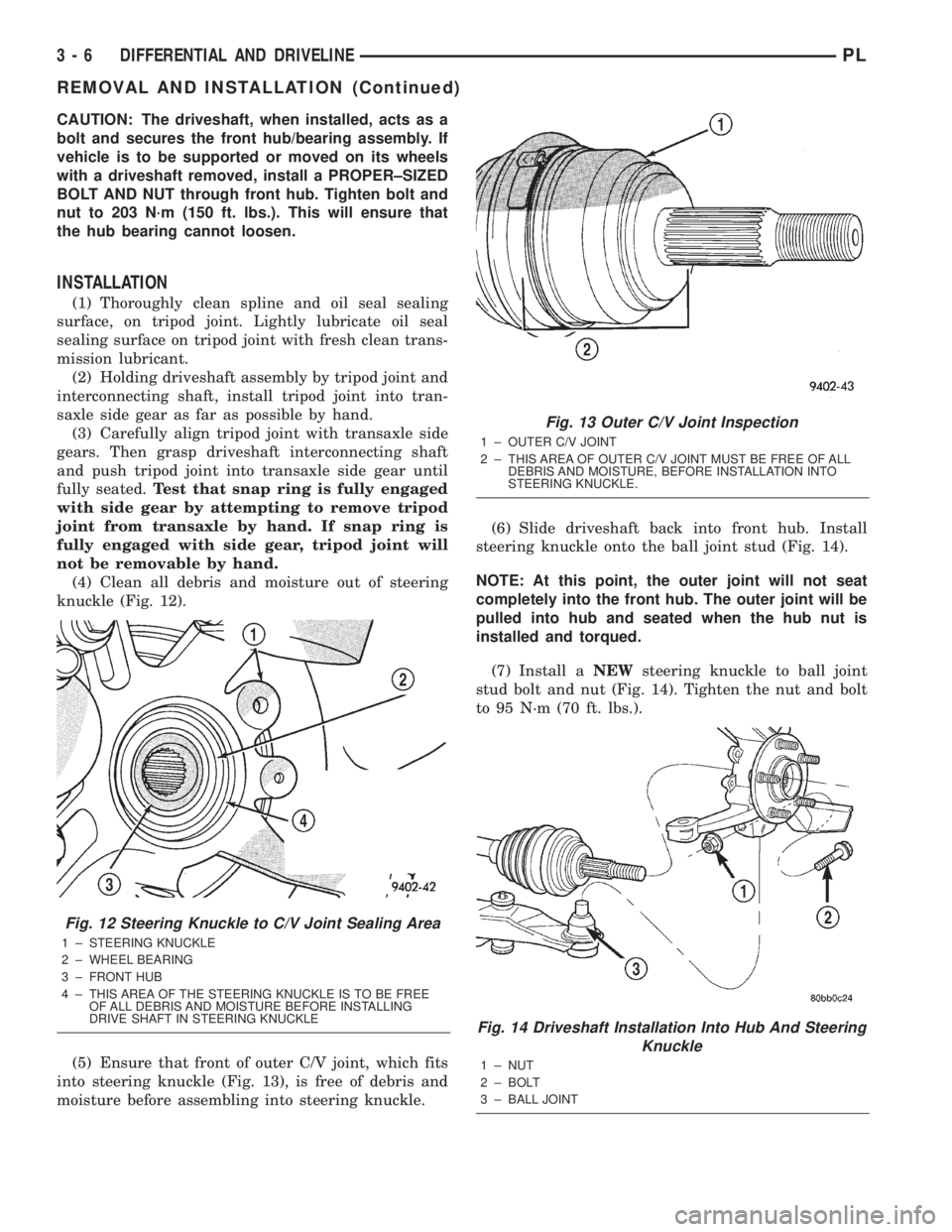
(4) Clean all debris and moisture out of steering
knuckle (Fig. 12).
(5) Ensure that front of outer C/V joint, which fits
into steering knuckle (Fig. 13), is free of debris and
moisture before assembling into steering knuckle.(6) Slide driveshaft back into front hub. Install
steering knuckle onto the ball joint stud (Fig. 14).
NOTE: At this point, the outer joint will not seat
completely into the front hub. The outer joint will be
pulled into hub and seated when the hub nut is
installed and torqued.
(7) Install aNEWsteering knuckle to ball joint
stud bolt and nut (Fig. 14). Tighten the nut and bolt
to 95 N´m (70 ft. lbs.).
Fig. 12 Steering Knuckle to C/V Joint Sealing Area
1 ± STEERING KNUCKLE
2 ± WHEEL BEARING
3 ± FRONT HUB
4 ± THIS AREA OF THE STEERING KNUCKLE IS TO BE FREE
OF ALL DEBRIS AND MOISTURE BEFORE INSTALLING
DRIVE SHAFT IN STEERING KNUCKLE
Fig. 13 Outer C/V Joint Inspection
1 ± OUTER C/V JOINT
2 ± THIS AREA OF OUTER C/V JOINT MUST BE FREE OF ALL
DEBRIS AND MOISTURE, BEFORE INSTALLATION INTO
STEERING KNUCKLE.
Fig. 14 Driveshaft Installation Into Hub And Steering
Knuckle
1 ± NUT
2 ± BOLT
3 ± BALL JOINT
3 - 6 DIFFERENTIAL AND DRIVELINEPL
REMOVAL AND INSTALLATION (Continued)
Page 78 of 1285
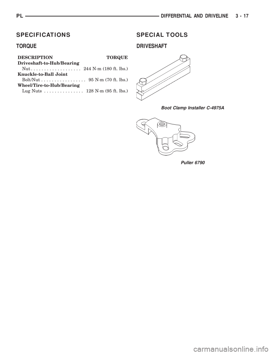
SPECIFICATIONS
TORQUE
DESCRIPTION TORQUE
Driveshaft-to-Hub/Bearing
Nut................... 244N´m(180 ft. lbs.)
Knuckle-to-Ball Joint
Bolt/Nut................. 95N´m(70ft.lbs.)
Wheel/Tire-to-Hub/Bearing
Lug Nuts............... 128N´m(95ft.lbs.)
SPECIAL TOOLS
DRIVESHAFT
Boot Clamp Installer C-4975A
Puller 6790
PLDIFFERENTIAL AND DRIVELINE 3 - 17
Page 105 of 1285
(16) Reconnect the steering column lower coupling
to the steering column upper coupling (Fig. 38).
Install the coupling pinch bolt an tighten the pinch
bolt nut to a torque of 28 N´m (250 in. lbs.). Install
the pinch bolt retainer pin.
(17) Remove the steering wheel holder (Fig. 37).
(18) While looking under the instrument panel at
the lower coupling, rotate the steering wheel back-
and-forth to verify that the lower coupling does not
squeak against the dash-to-coupling seal.
(19) Reconnect the battery negative terminal.
(20) Check the stop lamps to verify they are oper-
ating properly and not staying on when the pedal is
in the released position.
(21) Road test the vehicle to ensure proper opera-
tion of the brakes.
WITH MANUAL TRANSAXLE
REMOVAL
(1) Remove the instrument panel. Refer to the
INSTRUMENT PANELS AND SYSTEMS group in
this service manual for the required procedure.
(2) Depress and hold the brake pedal while rotat-
ing the brake lamp switch (Fig. 39) in a counterclock-
wise direction approximately 30 degrees.
(3) Pull the switch rearward and remove it from
its mounting bracket.
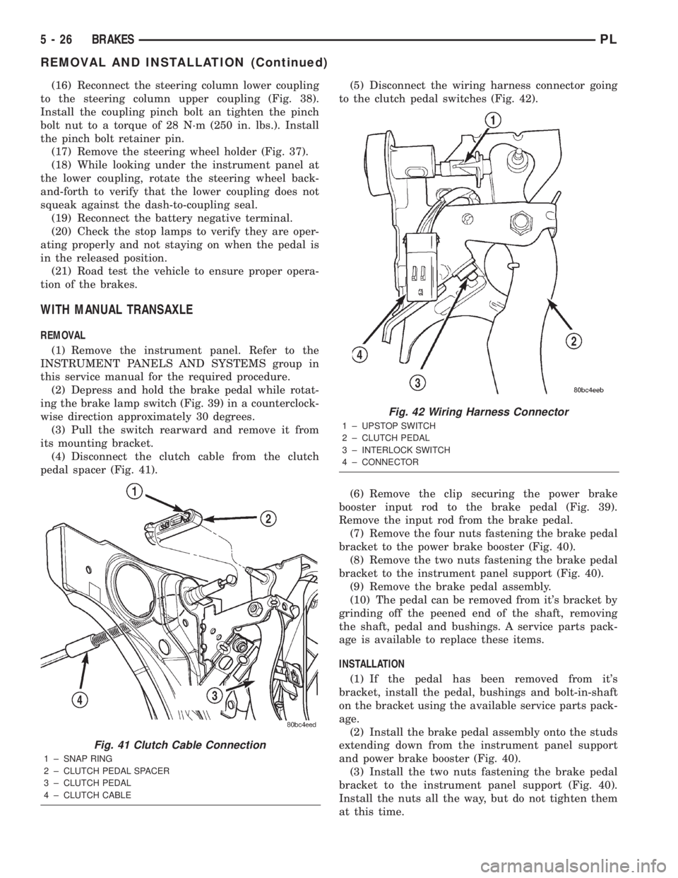
(4) Disconnect the clutch cable from the clutch
pedal spacer (Fig. 41).(5) Disconnect the wiring harness connector going
to the clutch pedal switches (Fig. 42).
(6) Remove the clip securing the power brake
booster input rod to the brake pedal (Fig. 39).
Remove the input rod from the brake pedal.
(7) Remove the four nuts fastening the brake pedal
bracket to the power brake booster (Fig. 40).
(8) Remove the two nuts fastening the brake pedal
bracket to the instrument panel support (Fig. 40).
(9) Remove the brake pedal assembly.
(10) The pedal can be removed from it's bracket by
grinding off the peened end of the shaft, removing
the shaft, pedal and bushings. A service parts pack-
age is available to replace these items.
INSTALLATION
(1) If the pedal has been removed from it's
bracket, install the pedal, bushings and bolt-in-shaft
on the bracket using the available service parts pack-
age.
(2) Install the brake pedal assembly onto the studs
extending down from the instrument panel support
and power brake booster (Fig. 40).
(3) Install the two nuts fastening the brake pedal
bracket to the instrument panel support (Fig. 40).
Install the nuts all the way, but do not tighten them
at this time.
Fig. 41 Clutch Cable Connection
1 ± SNAP RING
2 ± CLUTCH PEDAL SPACER
3 ± CLUTCH PEDAL
4 ± CLUTCH CABLE
Fig. 42 Wiring Harness Connector
1 ± UPSTOP SWITCH
2 ± CLUTCH PEDAL
3 ± INTERLOCK SWITCH
4 ± CONNECTOR
5 - 26 BRAKESPL
REMOVAL AND INSTALLATION (Continued)
Page 111 of 1285
CAUTION: Use only a new brake booster input rod-
to-brake pedal retaining clip to ensure proper
retainment.
(4) Connect the power brake booster input rod-to-
brake pedal pin. Install a new retaining clip. Do not
use the old clip.
(5) Connect all previously removed vacuum hoses
to the vacuum check valve (Fig. 49).
(6) If the vehicle is equipped with ABS, install the
ICU mounting bracket on the frame rail using its
three bolts. Tighten the nuts to a torque of 23 N´m
(200 in. lbs.).
(7) If the vehicle is equipped with ABS, reinstall
the ICU. Refer to INTEGRATED CONTROL UNIT in
REMOVAL AND INSTALLATION within the
ANTILOCK BRAKE SYSTEM section of this service
manual group for the procedure.
(8) Install the master cylinder. For the master cyl-
inder without ABS removal and installation proce-
dure, refer to MASTER CYLINDER in this section of
this service manual group. For the master cylinder
with ABS removal and installation procedure, refer
to MASTER CYLINDER in the ANTILOCK BRAKE
SYSTEM section of this service manual group.
(9) Position the battery tray back in place. Install
the two bolts, then the two nuts mounting the bat-
tery tray to its bracket (Fig. 48). Tighten the two
bolts and nuts to a torque of 34 N´m (25 ft. lbs.).
(10) Reinstall the air cleaner box onto its grom-
meted alignment post (Fig. 48).
(11) Install the one nut and one bolt securing the
air cleaner box in place, then connect the wiring har-
ness connector at the air inlet sensor.
(12) Install the battery and clamp it in place.
(13) Connect the positive, then the negative
(ground) cable on the battery.
(14) Adjust the stop lamp switch as necessary.
Refer to STOP LAMP SWITCH in the ADJUST-
MENTS section of this group.
(15) Bleed the base brake system.
(16) Road test the vehicle to ensure proper opera-
tion of the brakes.
PROPORTIONING VALVE
NOTE: Before proceeding with this procedure,
review SERVICE WARNINGS AND CAUTIONS at the
beginning of REMOVAL AND INSTALLATION in this
section.
REMOVAL
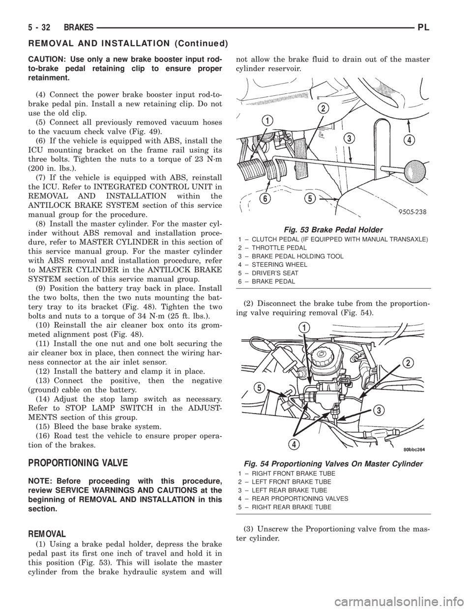
(1) Using a brake pedal holder, depress the brake
pedal past its first one inch of travel and hold it in
this position (Fig. 53). This will isolate the master
cylinder from the brake hydraulic system and willnot allow the brake fluid to drain out of the master
cylinder reservoir.
(2) Disconnect the brake tube from the proportion-
ing valve requiring removal (Fig. 54).
(3) Unscrew the Proportioning valve from the mas-
ter cylinder.
Fig. 53 Brake Pedal Holder
1 ± CLUTCH PEDAL (IF EQUIPPED WITH MANUAL TRANSAXLE)
2 ± THROTTLE PEDAL
3 ± BRAKE PEDAL HOLDING TOOL
4 ± STEERING WHEEL
5 ± DRIVER'S SEAT
6 ± BRAKE PEDAL
Fig. 54 Proportioning Valves On Master Cylinder
1 ± RIGHT FRONT BRAKE TUBE
2 ± LEFT FRONT BRAKE TUBE
3 ± LEFT REAR BRAKE TUBE
4 ± REAR PROPORTIONING VALVES
5 ± RIGHT REAR BRAKE TUBE
5 - 32 BRAKESPL
REMOVAL AND INSTALLATION (Continued)
Page 112 of 1285
INSTALLATION
(1) Lubricate the O-ring on the proportioning
valve. Make sure the O-ring on the proportioning
valve is new.
(2) Install the proportioning valve in its master
cylinder port. Tighten the proportioning valve to a
torque of 40 N´m (30 ft. lbs.).
(3) Connect the brake tube to the proportioning
valve (Fig. 54). Tighten the tube nut to a torque of 17
N´m (145 in. lbs.).
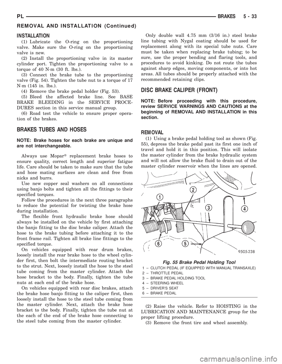
(4) Remove the brake pedal holder (Fig. 53).
(5) Bleed the affected brake line. See BASE
BRAKE BLEEDING in the SERVICE PROCE-
DURES section in this service manual group.
(6) Road test the vehicle to ensure proper opera-
tion of the brakes.
BRAKES TUBES AND HOSES
NOTE: Brake hoses for each brake are unique and
are not interchangeable.
Always use Mopartreplacement brake hoses to
ensure quality, correct length and superior fatigue
life. Care should be taken to make sure that the tube
and hose mating surfaces are clean and free from
nicks and burrs.
Use new copper seal washers on all connections
using banjo bolts and tighten all the fittings to their
specified torques.
Follow the procedures in the next three paragraphs
to reduce the potential for twisting the brake hose
during installation.
The flexible front hydraulic brake hose should
always be installed on the vehicle by first attaching
the banjo fitting to the disc brake caliper. Attach the
hose to the brake tubing before attaching it to the
front frame rail. Tighten all brake line fittings to the
specified torque.
On vehicles equipped with rear drum brakes,
loosely install the rear brake hose to the wheel cylin-
der first, then bolt the intermediate routing bracket
to the strut. Next, loosely install the hose to the steel
tube coming from the master cylinder. Attach the
hose bracket to the body. Finally, tighten the tube
nuts at each end of the brake hose.
On vehicles equipped with rear disc brakes, attach
the brake hose banjo fitting to the caliper first, then
loosely install the hose to the steel tube coming from
the master cylinder. Next, attach the brake hose
bracket to the body. Finally, tighten the tube nut at
the each of the end of the brake hose connecting to
the steel tube coming from the master cylinder.Only double wall 4.75 mm (3/16 in.) steel brake
line tubing with Nygal coating should be used for
replacement along with its special tube nuts. Care
must be taken when replacing brake tubing; to be
sure, use the proper bending and flaring tools, and
procedures to avoid kinking. Do not route the tubes
against sharp edges, moving components, or into hot
areas. All tubes should be properly attached with the
recommended retaining clips.
DISC BRAKE CALIPER (FRONT)
NOTE: Before proceeding with this procedure,
review SERVICE WARNINGS AND CAUTIONS at the
beginning of REMOVAL AND INSTALLATION in this
section.
REMOVAL
(1) Using a brake pedal holding tool as shown (Fig.
55), depress the brake pedal past its first one inch of
travel and hold it in this position. This will isolate
the master cylinder from the brake hydraulic system
and will not allow the brake fluid to drain out of the
master cylinder reservoir when the lines are opened.
(2) Raise the vehicle. Refer to HOISTING in the
LUBRICATION AND MAINTENANCE group for the
proper lifting procedure.
(3) Remove the front tire and wheel assembly.
Fig. 55 Brake Pedal Holding Tool
1 ± CLUTCH PEDAL (IF EQUIPPED WITH MANUAL TRANSAXLE)
2 ± THROTTLE PEDAL
3 ± BRAKE PEDAL HOLDING TOOL
4 ± STEERING WHEEL
5 ± DRIVER'S SEAT
6 ± BRAKE PEDAL
PLBRAKES 5 - 33
REMOVAL AND INSTALLATION (Continued)
Page 114 of 1285
(4) Install the caliper guide pin bolts and tighten
them to a torque of 22 N´m (192 in. lbs.) (Fig. 57).
(5) Install the banjo bolt connecting the brake hose
to the brake caliper (Fig. 56). Place one fitting
washer on each side of the hose fitting as the banjo
bolt is guided through the fitting. Install new wash-
ers if they are worn or damaged at all. Thread the
banjo bolt into the caliper and tighten it to a torque
of 48 N´m (35 ft. lbs.).
(6) Install the tire and wheel assembly. Tighten
the wheel mounting nuts to a torque of 135 N´m (100
ft. lbs.).
(7) Lower the vehicle.
(8) Remove the brake pedal holding tool.
(9) Bleed the caliper as necessary. Refer to BASE
BRAKE BLEEDING in the SERVICE PROCE-
DURES section in this service manual group.
(10) Road test the vehicle and make several stops
to wear off any foreign material on the brakes and to
seat the brake pads.
DISC BRAKE SHOES (FRONT)
NOTE: Before proceeding with this procedure,
review SERVICE WARNINGS AND CAUTIONS at the
beginning of REMOVAL AND INSTALLATION in this
section.
NOTE: Vehicles that are equipped with optional
Four-wheel-disc brake system use a different lining
material on the front disc brake shoes than vehicles
with front disc and rear drum brakes. When new
brake shoes are installed, be sure the brake shoes
for the correct type of brake system are used.
REMOVAL
(1) Raise the vehicle. Refer to HOISTING in the
LUBRICATION AND MAINTENANCE group for the
proper lifting procedure.
(2) Remove both front tire and wheel assemblies
from vehicle.
(3) Begin on one side of the vehicle.
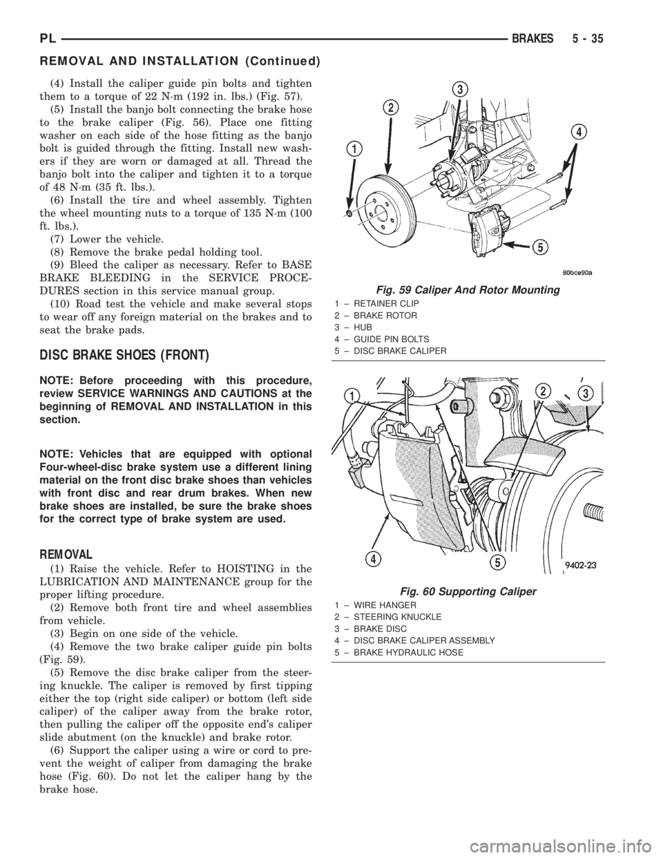
(4) Remove the two brake caliper guide pin bolts
(Fig. 59).
(5) Remove the disc brake caliper from the steer-
ing knuckle. The caliper is removed by first tipping
either the top (right side caliper) or bottom (left side
caliper) of the caliper away from the brake rotor,
then pulling the caliper off the opposite end's caliper
slide abutment (on the knuckle) and brake rotor.
(6) Support the caliper using a wire or cord to pre-
vent the weight of caliper from damaging the brake
hose (Fig. 60). Do not let the caliper hang by the
brake hose.
Fig. 59 Caliper And Rotor Mounting
1 ± RETAINER CLIP
2 ± BRAKE ROTOR
3 ± HUB
4 ± GUIDE PIN BOLTS
5 ± DISC BRAKE CALIPER
Fig. 60 Supporting Caliper
1 ± WIRE HANGER
2 ± STEERING KNUCKLE
3 ± BRAKE DISC
4 ± DISC BRAKE CALIPER ASSEMBLY
5 ± BRAKE HYDRAULIC HOSE
PLBRAKES 5 - 35
REMOVAL AND INSTALLATION (Continued)
Page 116 of 1285
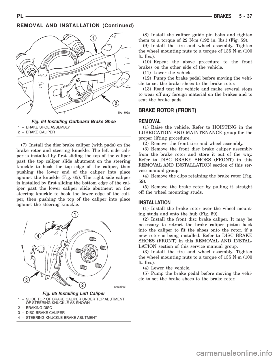
(7) Install the disc brake caliper (with pads) on the
brake rotor and steering knuckle. The left side cali-
per is installed by first sliding the top of the caliper
past the top caliper slide abutment on the steering
knuckle to hook the top edge of the caliper, then
pushing the lower end of the caliper into place
against the knuckle (Fig. 65). The right side caliper
is installed by first sliding the bottom edge of the cal-
iper past the lower caliper slide abutment on the
steering knuckle to hook the lower edge of the cali-
per, then pushing the top of the caliper into place
against the steering knuckle.(8) Install the caliper guide pin bolts and tighten
them to a torque of 22 N´m (192 in. lbs.) (Fig. 59).
(9) Install the tire and wheel assembly. Tighten
the wheel mounting nuts to a torque of 135 N´m (100
ft. lbs.).
(10) Repeat the above procedure to the front
brakes on the other side of the vehicle.
(11) Lower the vehicle.
(12) Pump the brake pedal before moving the vehi-
cle to set the brake shoes to the brake rotor.
(13) Road test the vehicle and make several stops
to wear off any foreign material on the brakes and to
seat the brake pads.
BRAKE ROTOR (FRONT)
REMOVAL
(1) Raise the vehicle. Refer to HOISTING in the
LUBRICATION AND MAINTENANCE group for the
proper lifting procedure.
(2) Remove the front tire and wheel assembly.
(3) Remove the front disc brake caliper assembly
from the brake rotor and store it out of the way.
Refer to DISC BRAKE SHOES (FRONT) in this
REMOVAL AND INSTALLATION section of this ser-
vice manual group.
(4) Remove the clips retaining the brake rotor (Fig.
59).
(5) Remove the brake rotor by pulling it straight
off the wheel mounting studs.
INSTALLATION
(1) Install the brake rotor over the wheel mount-
ing studs and onto the hub (Fig. 59).
(2) Install the front disc brake caliper. It may be
necessary to retract the brake caliper piston back
into the caliper to fit the shoes onto the rotor, if a
new rotor is being installed. Refer to DISC BRAKE
SHOES (FRONT) in this REMOVAL AND INSTAL-
LATION section of this service manual group.
(3) Install the tire and wheel assembly. Tighten
the wheel mounting nuts to a torque of 135 N´m (100
ft. lbs.).
(4) Lower the vehicle.
(5) Pump the brake pedal before moving the vehi-
cle to set the brake shoes to the brake rotor.
Fig. 64 Installing Outboard Brake Shoe
1 ± BRAKE SHOE ASSEMBLY
2 ± BRAKE CALIPER
Fig. 65 Installing Left Caliper
1 ± SLIDE TOP OF BRAKE CALIPER UNDER TOP ABUTMENT
OF STEERING KNUCKLE AS SHOWN
2 ± BRAKING DISC
3 ± DISC BRAKE CALIPER
4 ± STEERING KNUCKLE BRAKE ABUTMENT
PLBRAKES 5 - 37
REMOVAL AND INSTALLATION (Continued)
Page 118 of 1285
(1) Completely retract the caliper piston back into
piston bore of the caliper.
(2) Lubricate both adapter caliper slide abutments
with a liberal amount of MopartMultipurpose Lubri-
cant, or an equivalent.
CAUTION: Use care when installing the caliper
assembly onto adapter so the guide pin bushings
and sleeves do not get damaged by the mounting
bosses on adapter.
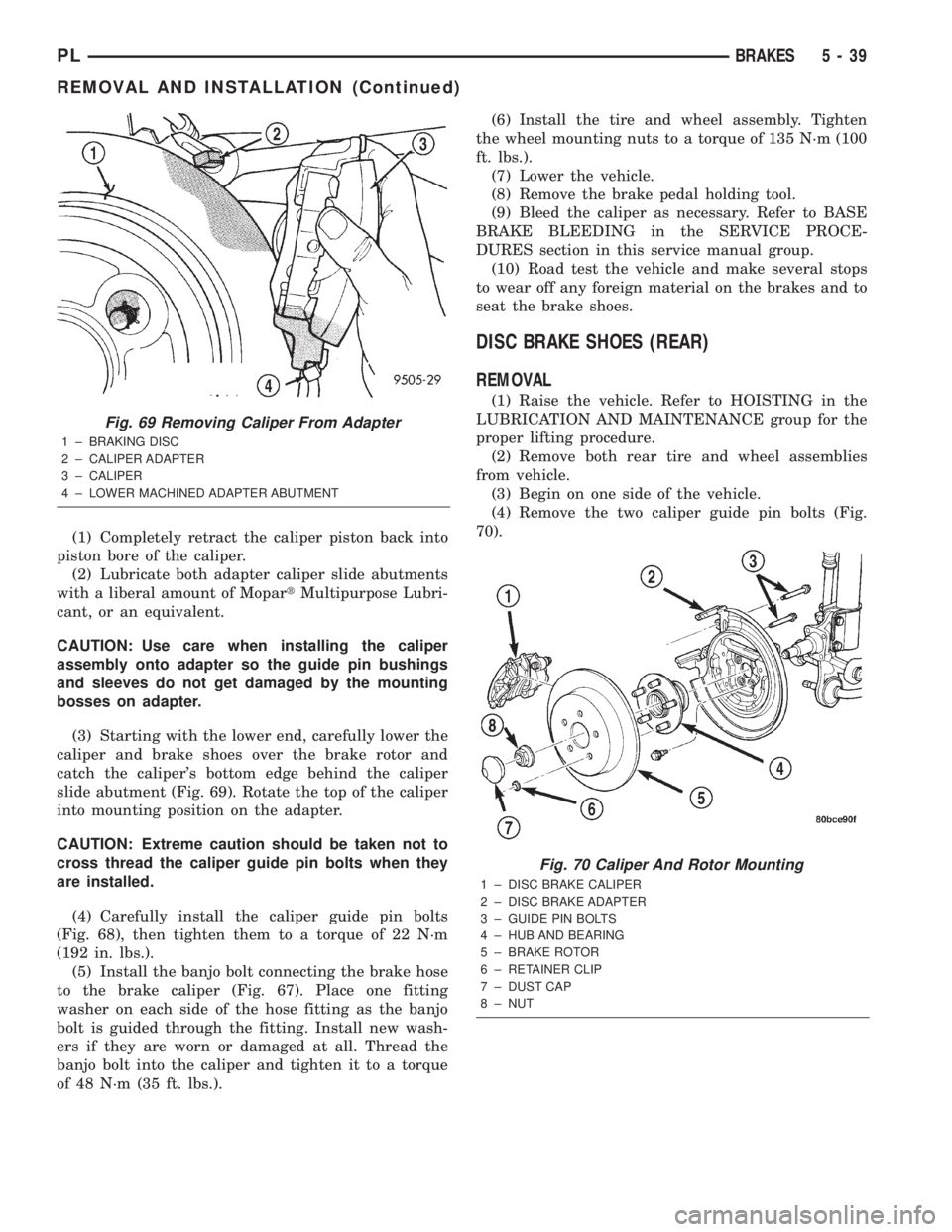
(3) Starting with the lower end, carefully lower the
caliper and brake shoes over the brake rotor and
catch the caliper's bottom edge behind the caliper
slide abutment (Fig. 69). Rotate the top of the caliper
into mounting position on the adapter.
CAUTION: Extreme caution should be taken not to
cross thread the caliper guide pin bolts when they
are installed.
(4) Carefully install the caliper guide pin bolts
(Fig. 68), then tighten them to a torque of 22 N´m
(192 in. lbs.).
(5) Install the banjo bolt connecting the brake hose
to the brake caliper (Fig. 67). Place one fitting
washer on each side of the hose fitting as the banjo
bolt is guided through the fitting. Install new wash-
ers if they are worn or damaged at all. Thread the
banjo bolt into the caliper and tighten it to a torque
of 48 N´m (35 ft. lbs.).(6) Install the tire and wheel assembly. Tighten
the wheel mounting nuts to a torque of 135 N´m (100
ft. lbs.).
(7) Lower the vehicle.
(8) Remove the brake pedal holding tool.
(9) Bleed the caliper as necessary. Refer to BASE
BRAKE BLEEDING in the SERVICE PROCE-
DURES section in this service manual group.
(10) Road test the vehicle and make several stops
to wear off any foreign material on the brakes and to
seat the brake shoes.
DISC BRAKE SHOES (REAR)
REMOVAL
(1) Raise the vehicle. Refer to HOISTING in the
LUBRICATION AND MAINTENANCE group for the
proper lifting procedure.
(2) Remove both rear tire and wheel assemblies
from vehicle.
(3) Begin on one side of the vehicle.
(4) Remove the two caliper guide pin bolts (Fig.
70).
Fig. 69 Removing Caliper From Adapter
1 ± BRAKING DISC
2 ± CALIPER ADAPTER
3 ± CALIPER
4 ± LOWER MACHINED ADAPTER ABUTMENT
Fig. 70 Caliper And Rotor Mounting
1 ± DISC BRAKE CALIPER
2 ± DISC BRAKE ADAPTER
3 ± GUIDE PIN BOLTS
4 ± HUB AND BEARING
5 ± BRAKE ROTOR
6 ± RETAINER CLIP
7 ± DUST CAP
8 ± NUT
PLBRAKES 5 - 39
REMOVAL AND INSTALLATION (Continued)