2000 DODGE NEON wheel bolt torque
[x] Cancel search: wheel bolt torquePage 161 of 1285
CAUTION: When removing a wheel speed sensor
from the knuckle, do not use pliers on the sensor
head. This may damage the sensor head. If the sen-
sor has seized, use a hammer and a punch to tap
the edge of the sensor head ear, rocking the sensor
side-to-side until free.
(5) Carefully, remove the sensor head from the
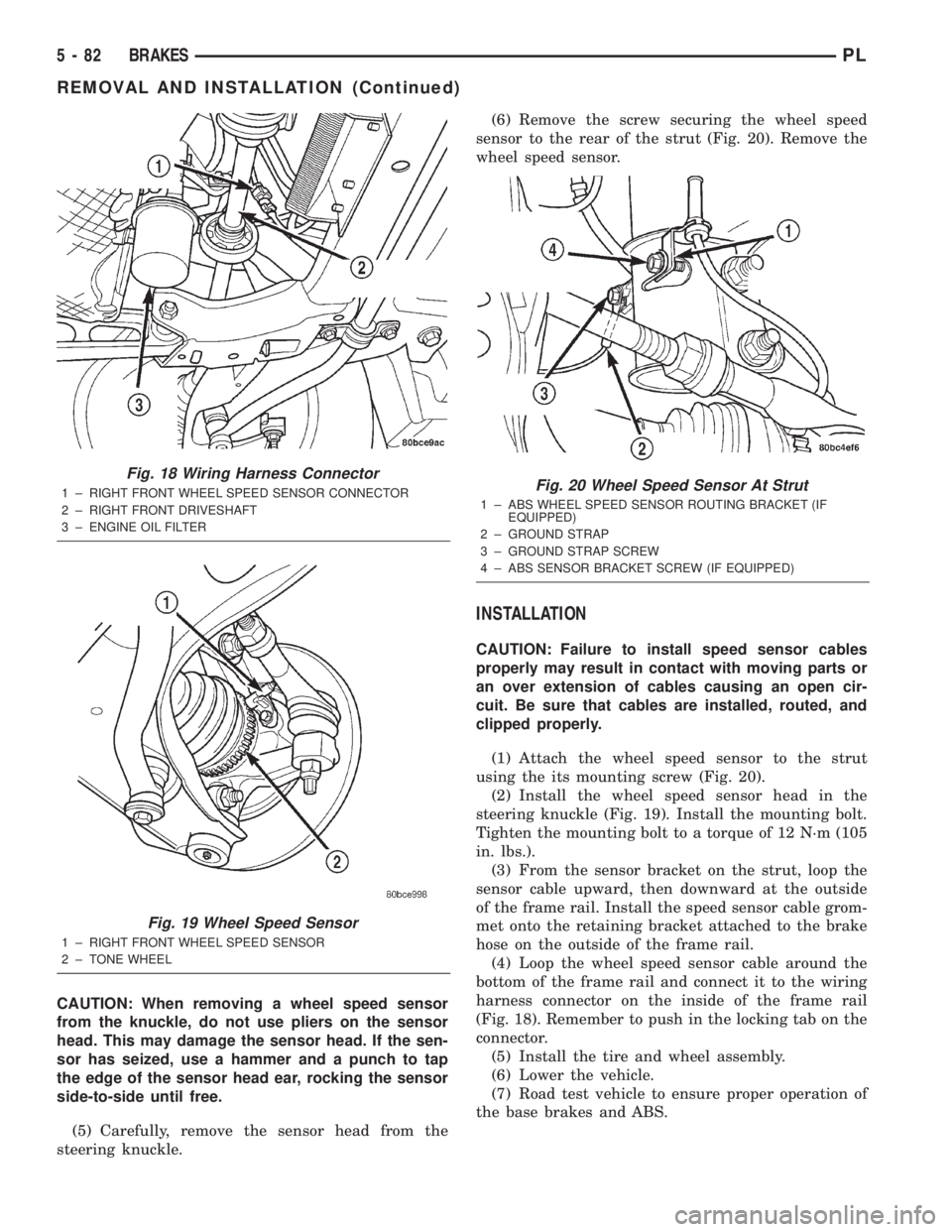
steering knuckle.(6) Remove the screw securing the wheel speed
sensor to the rear of the strut (Fig. 20). Remove the
wheel speed sensor.
INSTALLATION
CAUTION: Failure to install speed sensor cables
properly may result in contact with moving parts or
an over extension of cables causing an open cir-
cuit. Be sure that cables are installed, routed, and
clipped properly.
(1) Attach the wheel speed sensor to the strut
using the its mounting screw (Fig. 20).
(2) Install the wheel speed sensor head in the
steering knuckle (Fig. 19). Install the mounting bolt.
Tighten the mounting bolt to a torque of 12 N´m (105
in. lbs.).
(3) From the sensor bracket on the strut, loop the
sensor cable upward, then downward at the outside
of the frame rail. Install the speed sensor cable grom-
met onto the retaining bracket attached to the brake
hose on the outside of the frame rail.
(4) Loop the wheel speed sensor cable around the
bottom of the frame rail and connect it to the wiring
harness connector on the inside of the frame rail
(Fig. 18). Remember to push in the locking tab on the
connector.
(5) Install the tire and wheel assembly.
(6) Lower the vehicle.
(7) Road test vehicle to ensure proper operation of
the base brakes and ABS.
Fig. 18 Wiring Harness Connector
1 ± RIGHT FRONT WHEEL SPEED SENSOR CONNECTOR
2 ± RIGHT FRONT DRIVESHAFT
3 ± ENGINE OIL FILTER
Fig. 19 Wheel Speed Sensor
1 ± RIGHT FRONT WHEEL SPEED SENSOR
2 ± TONE WHEEL
Fig. 20 Wheel Speed Sensor At Strut
1 ± ABS WHEEL SPEED SENSOR ROUTING BRACKET (IF
EQUIPPED)
2 ± GROUND STRAP
3 ± GROUND STRAP SCREW
4 ± ABS SENSOR BRACKET SCREW (IF EQUIPPED)
5 - 82 BRAKESPL
REMOVAL AND INSTALLATION (Continued)
Page 162 of 1285
WHEEL SPEED SENSOR (REAR)
NOTE: Before proceeding with this procedure,
review SERVICE WARNINGS AND CAUTIONS at the
beginning of REMOVAL AND INSTALLATION in this
section.
REMOVAL
(1) Raise the vehicle. Refer to HOISTING in the
LUBRICATION AND MAINTENANCE group for the
proper lifting procedure.
(2) Remove the tire and wheel assembly from the
vehicle.
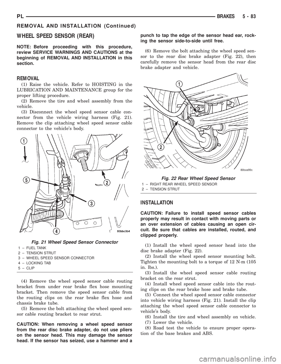
(3) Disconnect the wheel speed sensor cable con-
nector from the vehicle wiring harness (Fig. 21).
Remove the clip attaching wheel speed sensor cable
connector to the vehicle's body.
(4) Remove the wheel speed sensor cable routing
bracket from under rear brake flex hose mounting
bracket. Then remove the speed sensor cable from
the routing clips on the rear brake flex hose and
chassis brake tube.
(5) Remove the bolt attaching the wheel speed sen-
sor cable routing bracket to rear strut.
CAUTION: When removing a wheel speed sensor
from the rear disc brake adapter, do not use pliers
on the sensor head. This may damage the sensor
head. If the sensor has seized, use a hammer and apunch to tap the edge of the sensor head ear, rock-
ing the sensor side-to-side until free.
(6) Remove the bolt attaching the wheel speed sen-
sor to the rear disc brake adapter (Fig. 22), then
carefully remove the sensor head from the rear disc
brake adapter and vehicle.
INSTALLATION
CAUTION: Failure to install speed sensor cables
properly may result in contact with moving parts or
an over extension of cables causing an open cir-
cuit. Be sure that cables are installed, routed, and
clipped properly.
(1) Install the wheel speed sensor head into the
disc brake adapter (Fig. 22).
(2) Install the wheel speed sensor mounting bolt.
Tighten the mounting bolt to a torque of 12 N´m (105
in. lbs.).
(3) Install the wheel speed sensor cable routing
bracket on the rear strut.
(4) Install wheel speed sensor cable into the rout-
ing clips on the rear brake hose and brake tube.
(5) Connect the wheel speed sensor cable connector
into vehicle wiring harness (Fig. 21). Install the clip
attaching the wheel speed sensor cable connector to
vehicle's body.
(6) Install the tire and wheel assembly on vehicle.
(7) Lower the vehicle.
(8) Road test the vehicle to ensure proper opera-
tion of the base brakes and ABS.
Fig. 21 Wheel Speed Sensor Connector
1 ± FUEL TANK
2 ± TENSION STRUT
3 ± WHEEL SPEED SENSOR CONNECTOR
4 ± LOCKING TAB
5 ± CLIP
Fig. 22 Rear Wheel Speed Sensor
1 ± RIGHT REAR WHEEL SPEED SENSOR
2 ± TENSION STRUT
PLBRAKES 5 - 83
REMOVAL AND INSTALLATION (Continued)
Page 164 of 1285
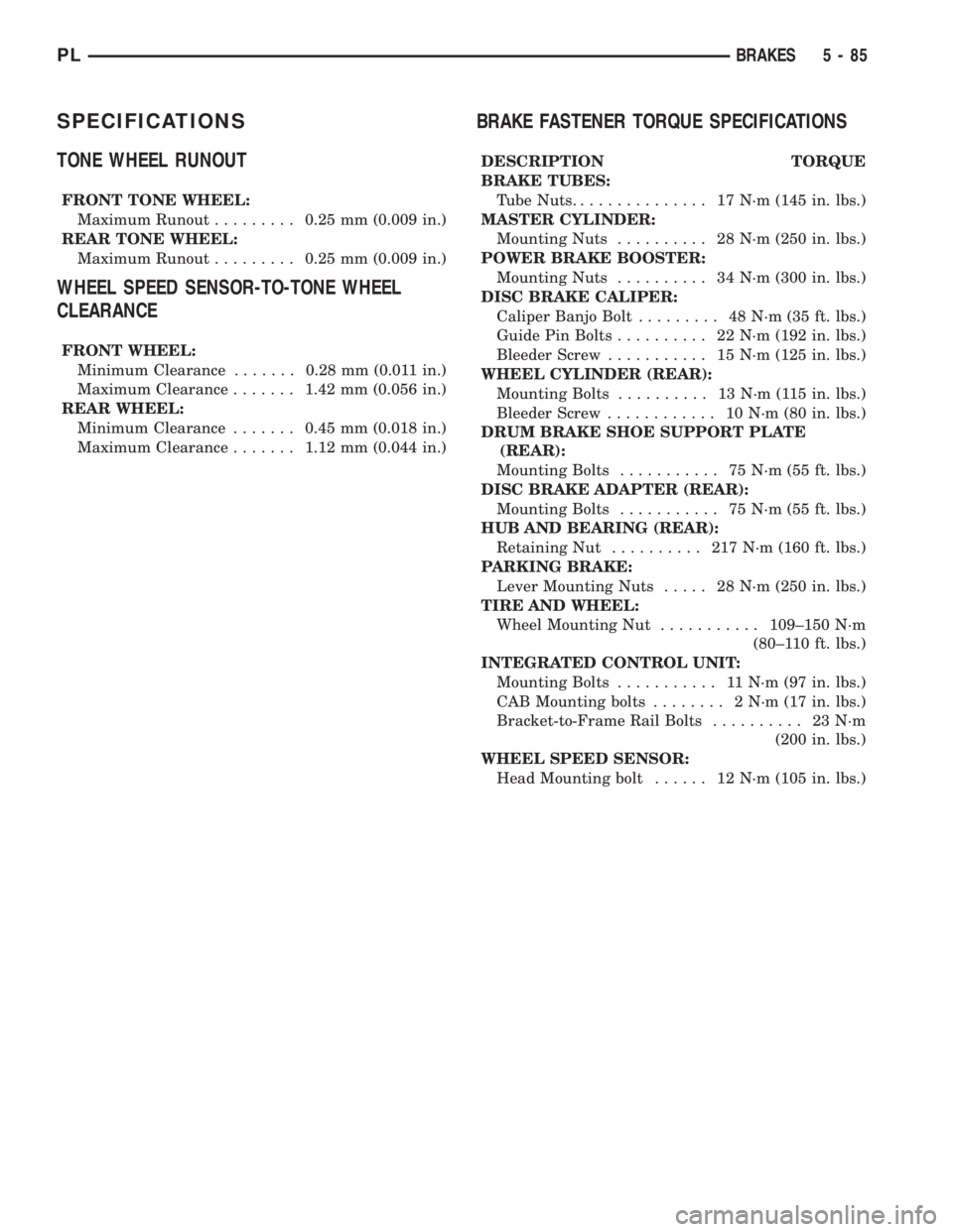
SPECIFICATIONS
TONE WHEEL RUNOUT
FRONT TONE WHEEL:
Maximum Runout.........0.25 mm (0.009 in.)
REAR TONE WHEEL:
Maximum Runout.........0.25 mm (0.009 in.)
WHEEL SPEED SENSOR-TO-TONE WHEEL
CLEARANCE
FRONT WHEEL:
Minimum Clearance.......0.28 mm (0.011 in.)
Maximum Clearance.......1.42 mm (0.056 in.)
REAR WHEEL:
Minimum Clearance.......0.45 mm (0.018 in.)
Maximum Clearance.......1.12 mm (0.044 in.)
BRAKE FASTENER TORQUE SPECIFICATIONS
DESCRIPTION TORQUE
BRAKE TUBES:
Tube Nuts............... 17N´m(145 in. lbs.)
MASTER CYLINDER:
Mounting Nuts.......... 28N´m(250 in. lbs.)
POWER BRAKE BOOSTER:
Mounting Nuts.......... 34N´m(300 in. lbs.)
DISC BRAKE CALIPER:
Caliper Banjo Bolt......... 48N´m(35ft.lbs.)
Guide Pin Bolts.......... 22N´m(192 in. lbs.)
Bleeder Screw........... 15N´m(125 in. lbs.)
WHEEL CYLINDER (REAR):
Mounting Bolts.......... 13N´m(115in.lbs.)
Bleeder Screw............ 10N´m(80in.lbs.)
DRUM BRAKE SHOE SUPPORT PLATE
(REAR):
Mounting Bolts........... 75N´m(55ft.lbs.)
DISC BRAKE ADAPTER (REAR):
Mounting Bolts........... 75N´m(55ft.lbs.)
HUB AND BEARING (REAR):
Retaining Nut.......... 217N´m(160 ft. lbs.)
PARKING BRAKE:
Lever Mounting Nuts..... 28N´m(250 in. lbs.)
TIRE AND WHEEL:
Wheel Mounting Nut...........109±150 N´m
(80±110 ft. lbs.)
INTEGRATED CONTROL UNIT:
Mounting Bolts........... 11N´m(97in.lbs.)
CAB Mounting bolts........ 2N´m(17in.lbs.)
Bracket-to-Frame Rail Bolts.......... 23N´m
(200 in. lbs.)
WHEEL SPEED SENSOR:
Head Mounting bolt...... 12N´m(105 in. lbs.)
PLBRAKES 5 - 85
Page 170 of 1285
DRIVE PLATE MISALIGNMENT
Common causes of misalignment are:
²Heat warping
²Mounting drive plate on a dirty crankshaft
flange
²Incorrect bolt tightening
²Improper seating on the crankshaft shoulder
²Loose crankshaft bolts
Clean the crankshaft flange before mounting the
drive plate. Dirt and grease on the flange surface
may misalign the flywheel, causing excessive runout.
Use new bolts when mounting drive plate to crank-
shaft. Tighten drive plate bolts to specified torque
only. Over-tightening can distort the drive plate hub
causing excessive runout.
CLUTCH CHATTER COMPLAINTS
For all clutch chatter complaints, do the following:
(1) Check for loose, misaligned, or broken engine
and transmission mounts. If present, they should be
corrected at this time. Test vehicle for chatter. If
chatter is gone, there is no need to go any further. If
chatter persists:
(2) Check to see if clutch cable routing is correct
and operates smoothly.
(3) Check for loose connections in drive train. Cor-
rect any problems and determine if clutch chatter
complaints have been satisfied. If not:
(4) Remove transaxle. See Group 21, Manual Tran-
saxle for procedure.
(5) Check to see if the release bearing is sticky or
binding. Replace bearing, if needed.
(6) Check linkage for excessive wear on the pivot
stud and fork fingers. Replace all worn parts.
(7) Check clutch assembly for contamination (dirt,
oil). Replace clutch assembly, if required.
(8) Check to see if the clutch disc hub splines are
damaged. Replace with new clutch assembly, if nec-
essary.
(9) Check input shaft splines for damage. Replace,
if necessary.
(10) Check for uneven wear on clutch fingers.
(11) Check for broken clutch cover diaphragm
spring fingers. Replace with new clutch assembly, if
necessary.
CLASH±INTO±REVERSE COMPLAINTS
Certain NV T350 (A-578) manual transaxles are
equipped with a reverse brake. It prevents clash
when shifting into reverse, but only if the vehicle is
not moving. See Group 21, Transaxle for further
diagnosis.
(1) Depress clutch pedal to floor and hold. After
three seconds, shift to reverse. If clash is present,
clutch has excessive spin time, and the reverse brake
may not be functioning.(2) Remove transaxle. See Group 21, Manual Tran-
saxle for procedure.
(3) Check the input shaft spline, clutch disc
splines, and release bearing for dry rust. If present,
clean rust off and apply a light coat of bearing grease
to the input shaft splines. Apply grease on the input
shaft splines only where the clutch disc slides. Verify
that the clutch disc slides freely along the input shaft
spline.
(4) Check to see if the clutch disc hub splines are
damaged, and replace with new clutch assembly if
required.
(5) Check the input shaft for damaged splines.
Replace as necessary.
(6) Check for broken clutch cover diaphragm
spring fingers.
(7) Install clutch assembly and transaxle.
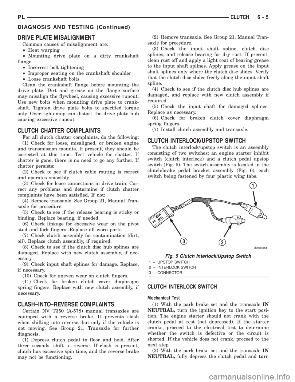
CLUTCH INTERLOCK/UPSTOP SWITCH
The clutch interlock/upstop switch is an assembly
consisting of two switches: an engine starter inhibit
switch (clutch interlock) and a clutch pedal upstop
switch (Fig. 5). The switch assembly is located in the
clutch/brake pedal bracket assembly (Fig. 6), each
switch being fastened by four plastic wing tabs.
CLUTCH INTERLOCK SWITCH
Mechanical Test
(1) With the park brake set and the transaxleIN
NEUTRAL,turn the ignition key to the start posi-
tion. The engine starter should not crank with the
clutch pedal at rest (not depressed). If the starter
cranks, proceed to the electrical test to determine
whether the switch is defective or the circuit is
shorted. If the vehicle does not crank, proceed to the
next step.
(2) With the park brake set and the transaxleIN
NEUTRAL,fully depress the clutch pedal and turn
Fig. 5 Clutch Interlock/Upstop Switch
1 ± UPSTOP SWITCH
2 ± INTERLOCK SWITCH
3 ± CONNECTOR
PLCLUTCH 6 - 5
DIAGNOSIS AND TESTING (Continued)
Page 178 of 1285
cover and flywheel. Heat buildup caused by slippage
can bake the oil residue onto the components. This
glaze-like residue ranges in color from amber to
black.
GREASE CONTAMINATION
Grease contamination is usually a product of over-
lubrication. During clutch service, apply only a small
amount of grease to the input shaft splines. Excess
grease may be thrown off during operation, contami-
nating the disc.
ROAD SPLASH/WATER CONTAMINATION
Road splash contamination is usually caused by
driving the vehicle through deep water puddles.
Water can be forced into the clutch housing, causing
clutch components to become contaminated. Facing of
disc will absorb moisture and bond to the flywheel
and/or, pressure plate, if vehicle is allowed to stand
for some time before use. If this condition occurs,
replacement of clutch assembly may be required.
Drive the vehicle until normal clutch operating tem-
perature has been obtained. This will dry off disc
assembly, pressure plate, and flywheel.
CLEANING PRECAUTIONS
Condensation from steam vapors tend to accumu-
late on the internal clutch mechanism when the vehi-
cle is steam cleaned. Facing of disc will absorb
moisture and will bond to flywheel and/or pressure
plate, if vehicle is allowed to stand for some time
before use. If this condition occurs, it may require
replacement of clutch assembly. After cleaning, drive
the vehicle to its normal clutch operating tempera-
ture. This will dry off disc assembly, pressure plate,
and flywheel.
SPECIFICATIONS
TORQUE
DESCRIPTION TORQUE
Modular Clutch-to-Drive Plate Bolts..... 88N´m
(65 ft. lbs.)
Transaxle-to-Engine Mounting Bolts...... 95N´m
(70 ft. lbs.)
PLCLUTCH 6 - 13
CLEANING AND INSPECTION (Continued)
Page 350 of 1285
(3) Install center console assembly. Refer to Group
23 Body, Floor Console Removal and Installation.
(4) Do not connect battery negative cable. Refer to
Diagnosis and Testing for Airbag System Test for the
proper procedures.
CLOCKSPRING
WARNING: DISCONNECT AND ISOLATE THE BAT-
TERY NEGATIVE (GROUND) CABLE BEFORE
BEGINNING ANY AIRBAG SYSTEM COMPONENT
REMOVAL OR INSTALLATION PROCEDURE. THIS
WILL DISABLE THE AIRBAG SYSTEM. FAILURE TO
DISCONNECT BATTERY COULD RESULT IN ACCI-
DENTAL AIRBAG DEPLOYMENT AND POSSIBLE
PERSONAL INJURY.
ALLOW SYSTEM CAPACITOR TO DISCHARGE
FOR 1 MINUTE BEFORE REMOVING ANY AIRBAG
COMPONENTS.
REMOVAL
(1) Place the front road wheels in the straight
ahead position then:
²Rotate the steering wheel half turn (180
degrees) to the right (clockwise).
²Lock column with ignition lock cylinder.
(2) Disconnect and isolate the battery negative
cable (Fig. 4).
(3) Wait one minute for the reserve capacitor to
discharge before removing non-deployed module.
(4) Remove steering wheel. Refer to Steering
Wheel Removal and Installation in this section.
(5) Remove upper and lower steering column
shrouds to gain access to clockspring wiring. Refer to
Group 8E Instrument Panel Systems, Steering Col-
umn Shroud Removal and Installation.
(6) Remove multi-function switch. Refer to Group
8J-Turn Signal and Hazard Warning Systems, Multi-
Function Switch Removal and Installation.
(7) Disconnect the 7-way connector between the
clockspring and the instrument panel wiring harness
at the base of the clockspring.
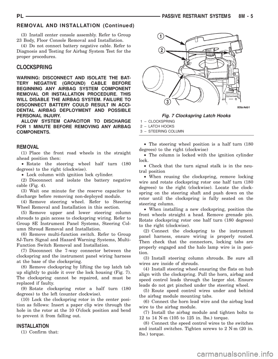
(8) Remove clockspring by lifting the top latch tab
up slightly to guide it over the lock housing (Fig. 7).
The clockspring cannot be repaired, and must be
replaced if faulty.
(9) Rotate clockspring rotor a half turn (180
degrees) to the left (counter clockwise).
(10) Lock the clockspring rotor in the center posi-
tion as follows: Insert a paper clip wire through the
hole in the rotor at the 10 O'clock position and bend
to prevent it from falling out.
INSTALLATION
(1) Confirm that:²The steering wheel position is a half turn (180
degrees) to the right (clockwise)
²The column is locked with the ignition cylinder
lock.
²Check that the turn signal stalk is in the neu-
tral position
²When reusing the clockspring, remove locking
wire and rotate clockspring rotor one half turn (180
degrees) to the right (clockwise). Locate the clock-
spring on the steering shaft and push down on the
rotor until the clockspring is fully seated on the
steering column.
²When installing a new clockspring, position the
front wheels straight a head. Remove grenade pin.
Rotate clockspring rotor one half turn (180 degrees)
to the right (clockwise).
(2) Connect the clockspring to the instrument
panel harness, ensure wiring is properly routed.
Then check that the connectors, locking tabs are
properly engaged and the halo lamp wire is in posi-
tion.
(3) Install steering column shrouds. Be sure all
wires are inside of shrouds.
(4) Install steering wheel ensuring the flats on hub
align with the clockspring. Pull the horn, airbag and
speed control leads through the larger slot. Ensure
leads do not get pinched under the steering wheel.
(5) Route speed control wires under and behind
the airbag module mounting tabs.
(6) Connect the horn lead wire and the airbag lead
wire to the airbag module.
(7) Install the airbag module and tighten bolts to
12 to 14 N´m (105 to 125 in. lbs.) torque.
(8) Connect the speed control wires to the switches
and install switches. Tighten screws to 2 N´m (20 in.
lbs.) torque.
Fig. 7 Clockspring Latch Hooks
1 ± CLOCKSPRING
2 ± LATCH HOOKS
3 ± STEERING COLUMN
PLPASSIVE RESTRAINT SYSTEMS 8M - 5
REMOVAL AND INSTALLATION (Continued)
Page 351 of 1285
(9) Do not connect the battery negative cable.
Refer to Diagnosis and Testing for Airbag System
Test procedures.
DRIVER AIRBAG MODULE
WARNING: DISCONNECT AND ISOLATE THE BAT-
TERY NEGATIVE (GROUND) CABLE BEFORE
BEGINNING ANY AIRBAG SYSTEM COMPONENT
REMOVAL OR INSTALLATION PROCEDURE. THIS
WILL DISABLE THE AIRBAG SYSTEM. FAILURE TO
DISCONNECT BATTERY COULD RESULT IN ACCI-
DENTAL AIRBAG DEPLOYMENT AND POSSIBLE
PERSONAL INJURY.
ALLOW SYSTEM CAPACITOR TO DISCHARGE
FOR 1 MINUTE BEFORE REMOVING ANY AIRBAG
COMPONENTS.
REMOVAL
When removing a deployed module, rubber gloves,
eye protection and long sleeved shirt should be worn,
as there may be deposits on the surface which could
irritate the skin and eyes.
(1) Disconnect and isolate the battery negative
cable (Fig. 4).
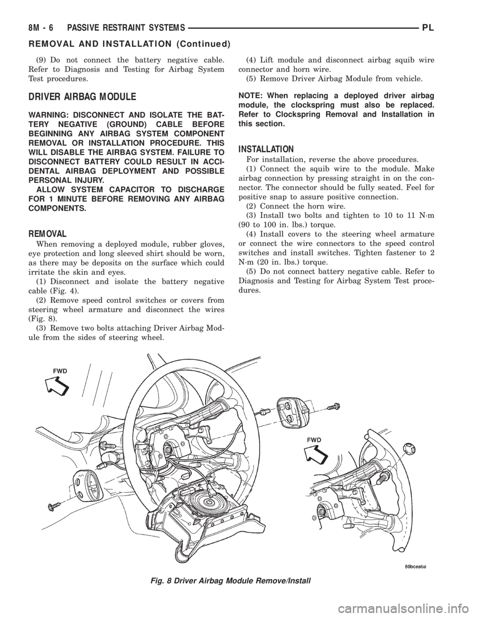
(2) Remove speed control switches or covers from
steering wheel armature and disconnect the wires
(Fig. 8).
(3) Remove two bolts attaching Driver Airbag Mod-
ule from the sides of steering wheel.(4) Lift module and disconnect airbag squib wire
connector and horn wire.
(5) Remove Driver Airbag Module from vehicle.
NOTE: When replacing a deployed driver airbag
module, the clockspring must also be replaced.
Refer to Clockspring Removal and Installation in
this section.
INSTALLATION
For installation, reverse the above procedures.
(1) Connect the squib wire to the module. Make
airbag connection by pressing straight in on the con-
nector. The connector should be fully seated. Feel for
positive snap to assure positive connection.
(2) Connect the horn wire.
(3) Install two bolts and tighten to 10 to 11 N´m
(90 to 100 in. lbs.) torque.
(4) Install covers to the steering wheel armature
or connect the wire connectors to the speed control
switches and install switches. Tighten fastener to 2
N´m (20 in. lbs.) torque.
(5) Do not connect battery negative cable. Refer to
Diagnosis and Testing for Airbag System Test proce-
dures.
Fig. 8 Driver Airbag Module Remove/Install
8M - 6 PASSIVE RESTRAINT SYSTEMSPL
REMOVAL AND INSTALLATION (Continued)
Page 353 of 1285
INSTALLATION
For installation, reverse the above procedures.
Ensure that the red locking tab is in the lock position
after installing the connector. Tighten trim screws to
2 N´m (20 in. lbs.) torque. Tighten the three module
retaining nuts to 22 to 34 N´m (200 to 300 in. lbs.)
torque. Do not connect battery negative cable. Refer
to Diagnosis and Testing for Airbag System Test pro-
cedures.
DEPLOYED MODULE
REMOVAL
When removing a deployed module, rubber gloves,
eye protection, and a long-sleeved shirt should be
worn, as there may be deposits on the surface which
could irritate the skin and eyes.
(1) Roll/fold airbag towards instrument panel.
(2) Close door over folded airbag and tape door
closed.
(3) Disconnect and isolate the battery negative
cable (Fig. 4).
(4) Remove instrument panel top cover. Refer to
Group 8E Instrument Panel Systems, Instrument
Panel Top Cover Removal and Installation.
(5) Remove three screws to glove box door and
remove door from instrument panel.
(6) Remove three passenger airbag cover screws
attaching cover to top of instrument panel (Fig. 9).
(7) Remove two passenger airbag cover screws
attaching cover to front lower instrument panel.
(8) Remove three module attaching nuts from the
support structure.
(9) Lift module up until the wire connector is visi-
ble and disconnect the 4-way wire connector from
module. Unlock the red locking tab and compress
lock to release the connector (Fig. 10).
INSTALLATION
For installation, reverse the above procedures.
Ensure that the red locking tab is in the lock position
after installing the connector. Tighten trim screws to
2 N´m (20 in. lbs.) torque. Tighten the module nuts to
22 to 34 N´m (200 to 300 in. lbs.) torque. Do not con-
nect battery negative cable. Refer to Diagnosis and
Testing for Airbag System Test procedures.
STEERING WHEEL
WARNING: DISCONNECT AND ISOLATE THE BAT-
TERY NEGATIVE (GROUND) CABLE BEFORE
BEGINNING ANY AIRBAG SYSTEM COMPONENT
REMOVAL OR INSTALLATION PROCEDURE. THIS
WILL DISABLE THE AIRBAG SYSTEM. FAILURE TO
DISCONNECT BATTERY COULD RESULT IN ACCI-DENTAL AIRBAG DEPLOYMENT AND POSSIBLE
PERSONAL INJURY.
ALLOW SYSTEM CAPACITOR TO DISCHARGE
FOR 1 MINUTE BEFORE REMOVING ANY AIRBAG
COMPONENTS.
REMOVAL
(1) Adjust the steering wheel so that the tires are
in the straight ahead position. Then:
(a) Rotate the steering wheel half turn (180
degrees) to the right (clockwise).
(b) Lock column with the ignition cylinder lock.
(2) Disconnect and isolate the battery negative
cable (Fig. 4).
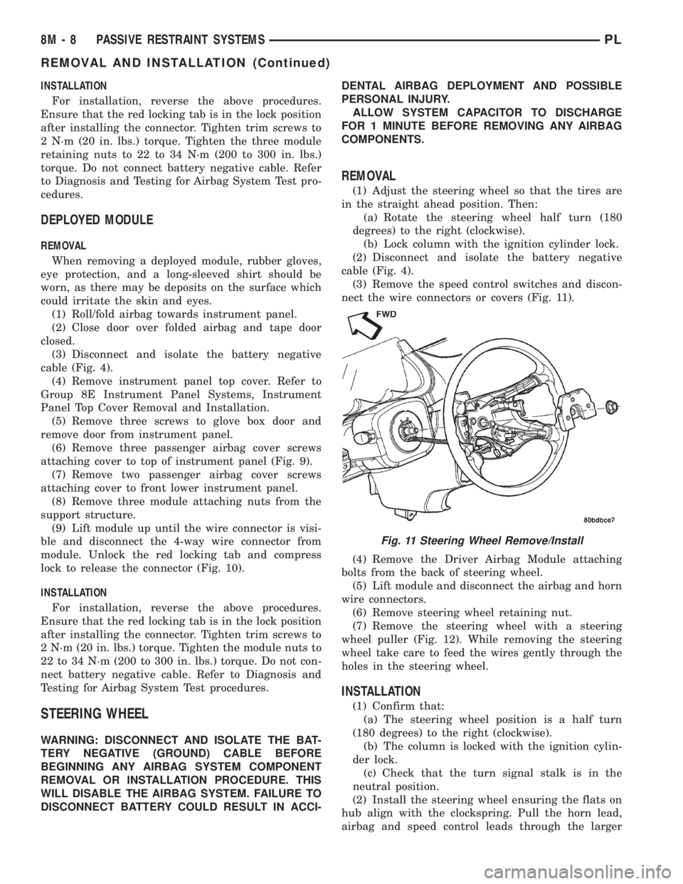
(3) Remove the speed control switches and discon-
nect the wire connectors or covers (Fig. 11).
(4) Remove the Driver Airbag Module attaching
bolts from the back of steering wheel.
(5) Lift module and disconnect the airbag and horn
wire connectors.
(6) Remove steering wheel retaining nut.
(7) Remove the steering wheel with a steering
wheel puller (Fig. 12). While removing the steering
wheel take care to feed the wires gently through the
holes in the steering wheel.
INSTALLATION
(1) Confirm that:
(a) The steering wheel position is a half turn
(180 degrees) to the right (clockwise).
(b) The column is locked with the ignition cylin-
der lock.
(c) Check that the turn signal stalk is in the
neutral position.
(2) Install the steering wheel ensuring the flats on
hub align with the clockspring. Pull the horn lead,
airbag and speed control leads through the larger
Fig. 11 Steering Wheel Remove/Install
8M - 8 PASSIVE RESTRAINT SYSTEMSPL
REMOVAL AND INSTALLATION (Continued)