2000 DODGE NEON wheel bolt torque
[x] Cancel search: wheel bolt torquePage 44 of 1285
SPECIFICATIONS
FRONT SUSPENSION FASTENER TORQUE
SPECIFICATIONS
DESCRIPTION TORQUE
STRUT ASSEMBLY:
Tower Nuts............. 34N´m(300 in. lbs.)
Steering Knuckle Nuts.............. 54N´m
(40 ft. lbs.) + 90É Turn
Strut Shaft Nut........... 75N´m(55ft.lbs.)
STEERING KNUCKLE:
Ball Joint Stud Pinch Bolt Nut........ 95N´m
(70 ft. lbs.)
Disc Brake Caliper Guide Bolts........ 22N´m
(192 in. lbs.)
WHEEL BEARING AND HUB:
Bearing Retainer Plate Bolts.......... 28N´m
(250 in. lbs.)
Driveshaft Hub Nut...... 244N´m(180 ft. lbs.)
Wheel Mounting Nuts...........109-150 N´m
(80-110 ft. lbs.)
STEERING GEAR:
Crossmember Bolts........ 68N´m(50ft.lbs.)
Tie Rod Adjusting Jam Nut . . 75 N´m (55 ft. lbs.)
Tie Rod End Steering Knuckle Nut..... 54N´m
(40 ft. lbs.)
LOWER CONTROL ARM:
Front Pivot Bolt......... 163N´m(120 ft. lbs.)
Rear Pivot Bolt......... 203N´m(150 ft. lbs.)
STABILIZER BAR:
Cushion Retainer Bolts.... 28N´m(250 in. lbs.)
Link Nut............... 23N´m(200 in. lbs.)
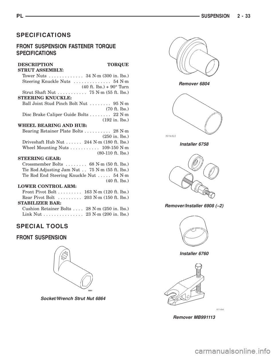
SPECIAL TOOLS
FRONT SUSPENSION
Socket/Wrench Strut Nut 6864
Remover 6804
Installer 6758
Remover/Installer 6908 (±2)
Installer 6760
Remover MB991113
PLSUSPENSION 2 - 33
Page 48 of 1285
For more information on the description and oper-
ation of an individual component, refer to the appli-
cable component heading in this section.
STRUT ASSEMBLY (REAR)
The rear strut assemblies support the weight of
the vehicle using coil springs positioned around
struts. The coil springs are contained between the
upper mount of the strut assembly and a lower
spring seat on the body of the strut.
The top of each strut assembly is bolted to the top
of the inner fender through a rubber isolated mount.
The bottom of the strut assembly attaches to the rear
knuckle using 2 thru-bolts with prevailing torque
nuts.
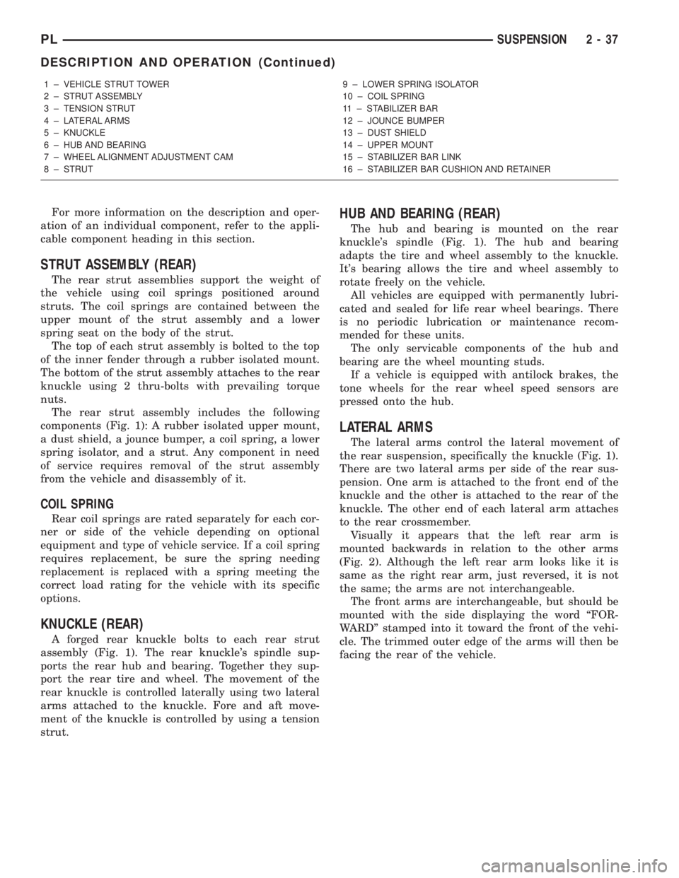
The rear strut assembly includes the following
components (Fig. 1): A rubber isolated upper mount,
a dust shield, a jounce bumper, a coil spring, a lower
spring isolator, and a strut. Any component in need
of service requires removal of the strut assembly
from the vehicle and disassembly of it.
COIL SPRING
Rear coil springs are rated separately for each cor-
ner or side of the vehicle depending on optional
equipment and type of vehicle service. If a coil spring
requires replacement, be sure the spring needing
replacement is replaced with a spring meeting the
correct load rating for the vehicle with its specific
options.
KNUCKLE (REAR)
A forged rear knuckle bolts to each rear strut
assembly (Fig. 1). The rear knuckle's spindle sup-
ports the rear hub and bearing. Together they sup-
port the rear tire and wheel. The movement of the
rear knuckle is controlled laterally using two lateral
arms attached to the knuckle. Fore and aft move-
ment of the knuckle is controlled by using a tension
strut.
HUB AND BEARING (REAR)
The hub and bearing is mounted on the rear
knuckle's spindle (Fig. 1). The hub and bearing
adapts the tire and wheel assembly to the knuckle.
It's bearing allows the tire and wheel assembly to
rotate freely on the vehicle.
All vehicles are equipped with permanently lubri-
cated and sealed for life rear wheel bearings. There
is no periodic lubrication or maintenance recom-
mended for these units.
The only servicable components of the hub and
bearing are the wheel mounting studs.
If a vehicle is equipped with antilock brakes, the
tone wheels for the rear wheel speed sensors are
pressed onto the hub.
LATERAL ARMS
The lateral arms control the lateral movement of
the rear suspension, specifically the knuckle (Fig. 1).
There are two lateral arms per side of the rear sus-
pension. One arm is attached to the front end of the
knuckle and the other is attached to the rear of the
knuckle. The other end of each lateral arm attaches
to the rear crossmember.
Visually it appears that the left rear arm is
mounted backwards in relation to the other arms
(Fig. 2). Although the left rear arm looks like it is
same as the right rear arm, just reversed, it is not
the same; the arms are not interchangeable.
The front arms are interchangeable, but should be
mounted with the side displaying the word ªFOR-
WARDº stamped into it toward the front of the vehi-
cle. The trimmed outer edge of the arms will then be
facing the rear of the vehicle.
1 ± VEHICLE STRUT TOWER
2 ± STRUT ASSEMBLY
3 ± TENSION STRUT
4 ± LATERAL ARMS
5 ± KNUCKLE
6 ± HUB AND BEARING
7 ± WHEEL ALIGNMENT ADJUSTMENT CAM
8 ± STRUT9 ± LOWER SPRING ISOLATOR
10 ± COIL SPRING
11 ± STABILIZER BAR
12 ± JOUNCE BUMPER
13 ± DUST SHIELD
14 ± UPPER MOUNT
15 ± STABILIZER BAR LINK
16 ± STABILIZER BAR CUSHION AND RETAINER
PLSUSPENSION 2 - 37
DESCRIPTION AND OPERATION (Continued)
Page 53 of 1285
²Place the link center sleeve and bushings
between the eye in the end of the stabilizer bar and
the link mounting bracket on the strut.
²Start the stabilizer bar link bolt with bushing
from the top, down through the stabilizer bar, inner
link bushings and sleeve, and strut link mounting
bracket.
²Install a lower bushing, then the nut. Do not
tighten the nut at this time.
(8) If the vehicle is equipped with the antilock
brake system (ABS), install the screw securing the
ABS wheel speed sensor bracket to the rear of the
strut assembly (Fig. 6). Tighten the mounting screw
to a torque of 13 N´m (120 in. lbs.).
(9) If the vehicle is equipped with rear drum
brakes, install the screw securing the brake hose
bracket to the rear of the strut assembly (Fig. 5).
Tighten the screw to a torque of 31 N´m (275 in. lbs.).
(10) Install the tire and wheel assembly on vehicle.
Tighten the wheel mounting stud nuts in proper
sequence until all nuts are torqued to half specifica-
tion. Repeat the tightening sequence, this time, to
full specified torque of 135 N´m (100 ft. lbs.).
(11) Lower the vehicle to ground level.
(12) Tighten the stabilizer bar link nut to a torque
of 23 N´m (200 in. lbs.).
(13) Set the rear toe on the vehicle to the required
specification if necessary. Refer to WHEEL ALIGN-
MENT in this service manual group.
KNUCKLE (REAR)
NOTE: Before proceeding with this procedure,
review SERVICE WARNINGS AND CAUTIONS at the
beginning of REMOVAL AND INSTALLATION in this
section.
REMOVAL
(1) Raise the vehicle. Refer to HOISTING in the
LUBRICATION AND MAINTENANCE group for the
proper lifting procedure.
(2) Remove the rear wheel and tire assembly from
the vehicle.
(3) If the vehicle is equipped with rear drum
brakes, remove the screw securing the brake hose
bracket to the rear of the strut assembly (Fig. 5).
(4) If the vehicle is equipped with the antilock
brake system (ABS), remove the screw securing the
ABS wheel speed sensor bracket to the rear of the
strut assembly (Fig. 6).
(5) If the vehicle is equipped with rear drum
brakes, remove any retainer clips from the wheel
mounting studs, then pull the brake drum off the
hub and bearing.
(6) If the vehicle is equipped with rear disc brakes
(Fig. 7), perform the following:²Remove the two guide pin bolts securing the
front disc brake caliper to the steering knuckle.
²Remove the disc brake caliper from the knuckle
and brake rotor.
²Hang the caliper out of the way using a wire
hanger or cord. Do not support the caliper by letting
it hang by the hydraulic hose.
²Remove any retainer clips from the wheel
mounting studs, then pull the brake rotor off the hub
and bearing.
(7) Remove the dust cap from the hub and bearing
assembly (Fig. 7).
(8) Remove the retaining nut, then the hub and
bearing from the knuckle's spindle (Fig. 7).
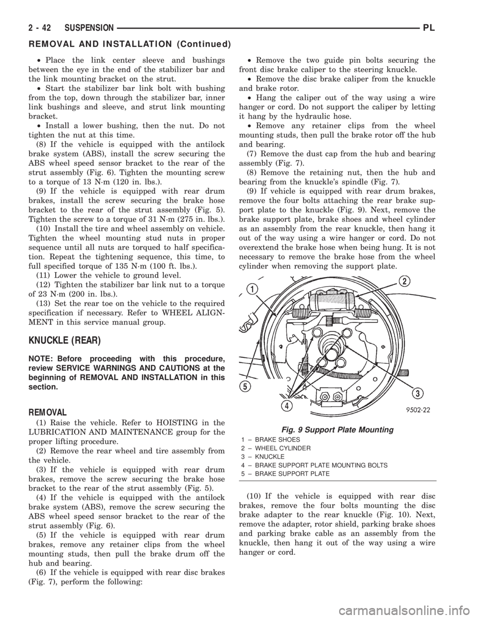
(9) If vehicle is equipped with rear drum brakes,
remove the four bolts attaching the rear brake sup-
port plate to the knuckle (Fig. 9). Next, remove the
brake support plate, brake shoes and wheel cylinder
as an assembly from the rear knuckle, then hang it
out of the way using a wire hanger or cord. Do not
overextend the brake hose when being hung. It is not
necessary to remove the brake hose from the wheel
cylinder when removing the support plate.
(10) If the vehicle is equipped with rear disc
brakes, remove the four bolts mounting the disc
brake adapter to the rear knuckle (Fig. 10). Next,
remove the adapter, rotor shield, parking brake shoes
and parking brake cable as an assembly from the
knuckle, then hang it out of the way using a wire
hanger or cord.Fig. 9 Support Plate Mounting
1 ± BRAKE SHOES
2 ± WHEEL CYLINDER
3 ± KNUCKLE
4 ± BRAKE SUPPORT PLATE MOUNTING BOLTS
5 ± BRAKE SUPPORT PLATE
2 - 42 SUSPENSIONPL
REMOVAL AND INSTALLATION (Continued)
Page 55 of 1285
the front side. Install the nut, but do not completely
tighten it at this time. The nut will need to be tight-
ened when the vehicle is at curb height.
(4) Install the rear bayonet bushing on the tension
strut. Be sure the stepped area of the bushing is
squarely seated into the hole in the knuckle.
(5) Install the rear tension strut retainer, then the
nut. To completely install the nut, place a wrench on
the flat formed into the tension strut and tighten the
nut (Fig. 12). Tighten the nut to a torque of 95 N´m
(70 ft. lbs.).
(6) If vehicle is equipped with rear drum brakes,
install the brake support plate on the knuckle and
attach it using it's four mounting bolts (Fig. 9).
Tighten the mounting bolts to a torque of 75 N´m (55
ft. lbs.).
(7) If the vehicle is equipped with rear disc brakes,
install the disc brake adapter on the knuckle and
attach it using it's four mounting bolts (Fig. 10).
Tighten the mounting bolts to a torque of 75 N´m (55
ft. lbs.).
(8) Install the hub and bearing on the knuckle's
spindle, then install a new retaining nut (Fig. 7). Do
not reuse the original nut. Tighten the nut to a
torque of 217 N´m (160 ft. lbs.).
(9) Install the dust cap on the end of the hub and
bearing (Fig. 7).
(10) If the vehicle is equipped with rear disc
brakes (Fig. 7), install the brake rotor and disc brake
caliper on the knuckle. Install the two guide pin bolts
securing the front disc brake caliper to the steering
knuckle. Tighten the guide pin bolts to a torque of 22
N´m (192 in. lbs.).
(11) If the vehicle is equipped with rear drum
brakes, install the screw securing the brake hose
bracket to the rear of the strut assembly (Fig. 5).
Tighten the screw to a torque of 31 N´m (275 in. lbs.).
(12) If the vehicle is equipped with the antilock
brake system (ABS), install the screw securing the
ABS wheel speed sensor bracket to the rear of the
strut assembly (Fig. 6). Tighten the mounting screw
to a torque of 13 N´m (120 in. lbs.).
(13) Install the tire and wheel assembly. Tighten
the wheel mounting nuts in proper sequence until all
nuts are torqued to half specification. Repeat the
tightening sequence, this time, to full specified
torque of 135 N´m (100 ft. lbs.).
(14) Lower the vehicle to ground level.
(15) Tighten the lateral arm-to-knuckle mounting
bolt nut to a torque of 95 N´m (70 ft. lbs.).
(16) Set the rear toe on the vehicle to the required
specification if necessary. Refer to WHEEL ALIGN-
MENT in this service manual group.HUB AND BEARING (REAR)
NOTE: Before proceeding with this procedure,
review SERVICE WARNINGS AND CAUTIONS at the
beginning of REMOVAL AND INSTALLATION in this
section.
REMOVAL
(1) Raise the vehicle. Refer to HOISTING in the
LUBRICATION AND MAINTENANCE group for the
proper lifting procedure.
(2) Remove the rear wheel and tire assembly from
the vehicle.
(3) If the vehicle is equipped with rear drum
brakes, remove any retainer clips from the wheel
mounting studs, then pull the brake drum off the
hub and bearing.
(4) If the vehicle is equipped with rear disc brakes
(Fig. 7), perform the following:
²Remove the two guide pin bolts securing the
front disc brake caliper to the steering knuckle.
²Remove the disc brake caliper from the knuckle
and brake rotor.
²Hang the caliper out of the way using a wire
hanger or cord. Do not support the caliper by letting
it hang by the hydraulic hose.
²Remove any retainer clips from the wheel
mounting studs, then pull the brake rotor off the hub
and bearing.
(5) Remove the dust cap from the hub and bearing
assembly (Fig. 7).
(6) Remove the retaining nut, then the hub and
bearing from the knuckle's spindle (Fig. 7).
INSTALLATION
(1) Install the hub and bearing on the knuckle's
spindle, then install a new retaining nut (Fig. 7). Do
not reuse the original nut. Tighten the nut to a
torque of 217 N´m (160 ft. lbs.).
(2) Install the dust cap on the end of the hub and
bearing (Fig. 7).
(3) If the vehicle is equipped with rear disc brakes
(Fig. 7), install the brake rotor and disc brake caliper
on the knuckle. Install the two guide pin bolts secur-
ing the front disc brake caliper to the steering
knuckle. Tighten the guide pin bolts to a torque of 22
N´m (192 in. lbs.).
(4) Install the tire and wheel assembly. Tighten
the wheel mounting nuts in proper sequence until all
nuts are torqued to half specification. Repeat the
tightening sequence, this time, to full specified
torque of 135 N´m (100 ft. lbs.).
(5) Lower the vehicle to ground level.
2 - 44 SUSPENSIONPL
REMOVAL AND INSTALLATION (Continued)
Page 56 of 1285
LATERAL ARMS
NOTE: Before proceeding with this procedure,
review SERVICE WARNINGS AND CAUTIONS at the
beginning of REMOVAL AND INSTALLATION in this
section.
Use the following procedure for removal and instal-
lation of one or both lateral arms on one side of the
vehicle's rear suspension.
REMOVAL
(1) Raise the vehicle. Refer to HOISTING in the
LUBRICATION AND MAINTENANCE group for the
proper lifting procedure.
(2) Remove the rear tire and wheel assembly.
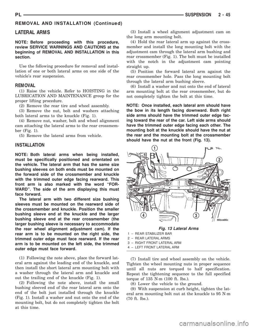
(3) Remove the nut, bolt and washers attaching
both lateral arms to the knuckle (Fig. 1).
(4) Remove nut, washer, bolt and wheel alignment
cam attaching the lateral arms to the rear crossmem-
ber (Fig. 1).
(5) Remove the lateral arms from vehicle.
INSTALLATION
NOTE: Both lateral arms when being installed,
must be specifically positioned and orientated on
the vehicle. The lateral arm that has the same size
bushing sleeves on both ends must be mounted on
the forward side of the crossmember and knuckle
with the trimmed outer edge facing rearward. This
front arm is also marked with the word ªFOR-
WARDº. The side of the arm displaying this must
face forward.
The lateral arm with two different size bushing
sleeves must be mounted on the rearward side of
the crossmember and knuckle. Position the smaller
bushing sleeve end at the knuckle and the larger
bushing sleeve end at the rear crossmember (the
larger bushing sleeve is necessary to accommodate
the rear wheel alignment adjustment cam). If the
rear arm is to be mounted on the right side, the
trimmed outer edge must face rearward. If the rear
arm is to be mounted on the left side, the trimmed
outer edge must face forward.
(1) Following the note above, place the forward lat-
eral arm against the leading end of the knuckle, and
then install the short lateral arm mounting bolt with
a washer through the lateral arm and knuckle and
out the trailing end of the knuckle (Fig. 1).
(2) Following the note above, install the small
bushing sleeved end of the rear lateral arm onto the
end of the bolt just installed through the knuckle
(Fig. 1). Install a washer and nut onto the end of the
mounting bolt, but do not completely tighten the bolt
at this time.(3) Install a wheel alignment adjustment cam on
the long arm mounting bolt.
(4) Hold the rear lateral arm up against the cross-
member and install the long mounting bolt with the
adjustment cam through the lateral arm bushing and
rear crossmember (Fig. 1). The bolt must be installed
with the notch in the adjustment cam pointing
straight up.
(5) Position the forward lateral arm against the
rear crossmember hole. Pass the long mounting bolt
through the lateral arm bushing sleeve.
(6) Install a washer and nut onto the end of lateral
arm mounting bolt at the rear crossmember, but do
not completely tighten the bolt at this time.
NOTE: Once installed, each lateral arm should have
the bow in its length facing downward. Both right
side arms should have the trimmed outer edge fac-
ing toward the rear of the car. Left side arms should
have the trimmed outer edge facing each other. The
mounting bolt at the knuckle should have the nut at
the rear and the mounting bolt at the crossmember
should have the nut at the front (Fig. 13).
(7) Install tire and wheel assembly on the vehicle.
Tighten the wheel mounting nuts in proper sequence
until all nuts are torqued to half specification.
Repeat the tightening sequence to the full specified
torque of 135 N´m (100 ft. lbs.).
(8) Lower the vehicle to the ground.
(9) With suspension at curb height, tighten the lat-
eral arm mounting bolt nut at the knuckle to 95 N´m
(70 ft. lbs.).
Fig. 13 Lateral Arms
1 ± REAR STABILIZER BAR
2 ± REAR LATERAL ARMS
3 ± RIGHT FRONT LATERAL ARM
4 ± LEFT FRONT LATERAL ARM
PLSUSPENSION 2 - 45
REMOVAL AND INSTALLATION (Continued)
Page 57 of 1285
(10) With suspension at curb height, tighten the
lateral arm mounting bolt nut at the crossmember to
88 N´m (65 ft. lbs.).
(11) Set the rear toe on the vehicle to the required
specification as necessary. Refer to WHEEL ALIGN-
MENT in this service manual group.
TENSION STRUT
NOTE: Before proceeding with this procedure,
review SERVICE WARNINGS AND CAUTIONS at the
beginning of REMOVAL AND INSTALLATION in this
section.
REMOVAL
(1) Raise the vehicle. Refer to HOISTING in the
LUBRICATION AND MAINTENANCE group for the
proper lifting procedure.
(2) Remove the rear wheel and tire assembly from
the vehicle.
(3) Disconnect the tension strut from the knuckle.
To do this, first hold the tension strut from turning
by using a wrench on the flat on the tension strut
and then remove the nut from the rear of the tension
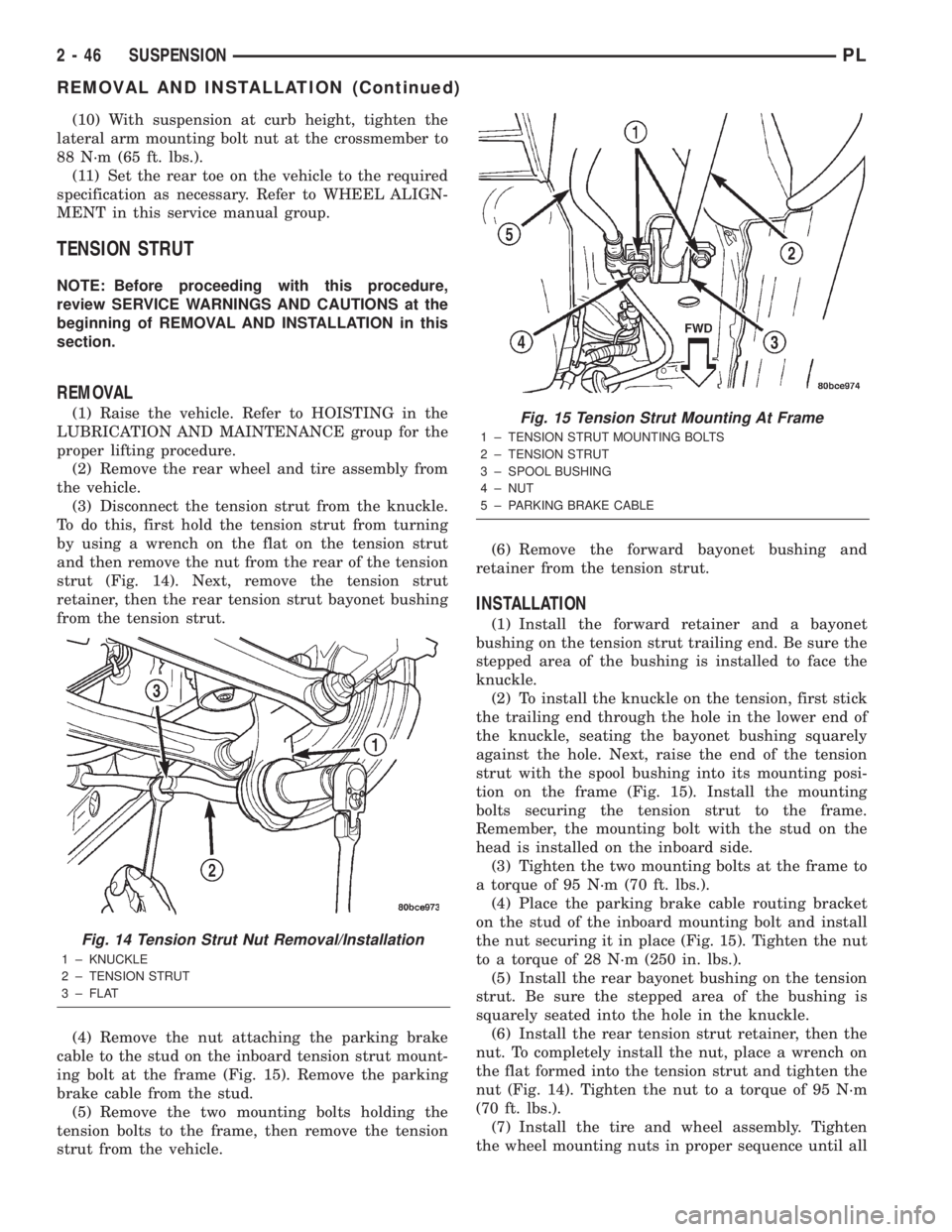
strut (Fig. 14). Next, remove the tension strut
retainer, then the rear tension strut bayonet bushing
from the tension strut.
(4) Remove the nut attaching the parking brake
cable to the stud on the inboard tension strut mount-
ing bolt at the frame (Fig. 15). Remove the parking
brake cable from the stud.
(5) Remove the two mounting bolts holding the
tension bolts to the frame, then remove the tension
strut from the vehicle.(6) Remove the forward bayonet bushing and
retainer from the tension strut.
INSTALLATION
(1) Install the forward retainer and a bayonet
bushing on the tension strut trailing end. Be sure the
stepped area of the bushing is installed to face the
knuckle.
(2) To install the knuckle on the tension, first stick
the trailing end through the hole in the lower end of
the knuckle, seating the bayonet bushing squarely
against the hole. Next, raise the end of the tension
strut with the spool bushing into its mounting posi-
tion on the frame (Fig. 15). Install the mounting
bolts securing the tension strut to the frame.
Remember, the mounting bolt with the stud on the
head is installed on the inboard side.
(3) Tighten the two mounting bolts at the frame to
a torque of 95 N´m (70 ft. lbs.).
(4) Place the parking brake cable routing bracket
on the stud of the inboard mounting bolt and install
the nut securing it in place (Fig. 15). Tighten the nut
to a torque of 28 N´m (250 in. lbs.).
(5) Install the rear bayonet bushing on the tension
strut. Be sure the stepped area of the bushing is
squarely seated into the hole in the knuckle.
(6) Install the rear tension strut retainer, then the
nut. To completely install the nut, place a wrench on
the flat formed into the tension strut and tighten the
nut (Fig. 14). Tighten the nut to a torque of 95 N´m
(70 ft. lbs.).
(7) Install the tire and wheel assembly. Tighten
the wheel mounting nuts in proper sequence until all
Fig. 14 Tension Strut Nut Removal/Installation
1 ± KNUCKLE
2 ± TENSION STRUT
3 ± FLAT
Fig. 15 Tension Strut Mounting At Frame
1 ± TENSION STRUT MOUNTING BOLTS
2 ± TENSION STRUT
3 ± SPOOL BUSHING
4 ± NUT
5 ± PARKING BRAKE CABLE
2 - 46 SUSPENSIONPL
REMOVAL AND INSTALLATION (Continued)
Page 58 of 1285
nuts are torqued to half specification. Repeat the
tightening sequence, this time, to full specified
torque of 135 N´m (100 ft. lbs.).
(8) Lower the vehicle to ground level.
(9) Set the rear toe on the vehicle to the required
specification if necessary. Refer to WHEEL ALIGN-
MENT in this service manual group.
STABILIZER BAR (REAR)
NOTE: Before proceeding with this procedure,
review SERVICE WARNINGS AND CAUTIONS at the
beginning of REMOVAL AND INSTALLATION in this
section.
REMOVAL
(1) Raise the vehicle. Refer to HOISTING in the
LUBRICATION AND MAINTENANCE group for the
proper lifting procedure.
(2) Remove both rear wheel and tire assemblies
from the vehicle.
(3) Remove the nut from the end of each rear sta-
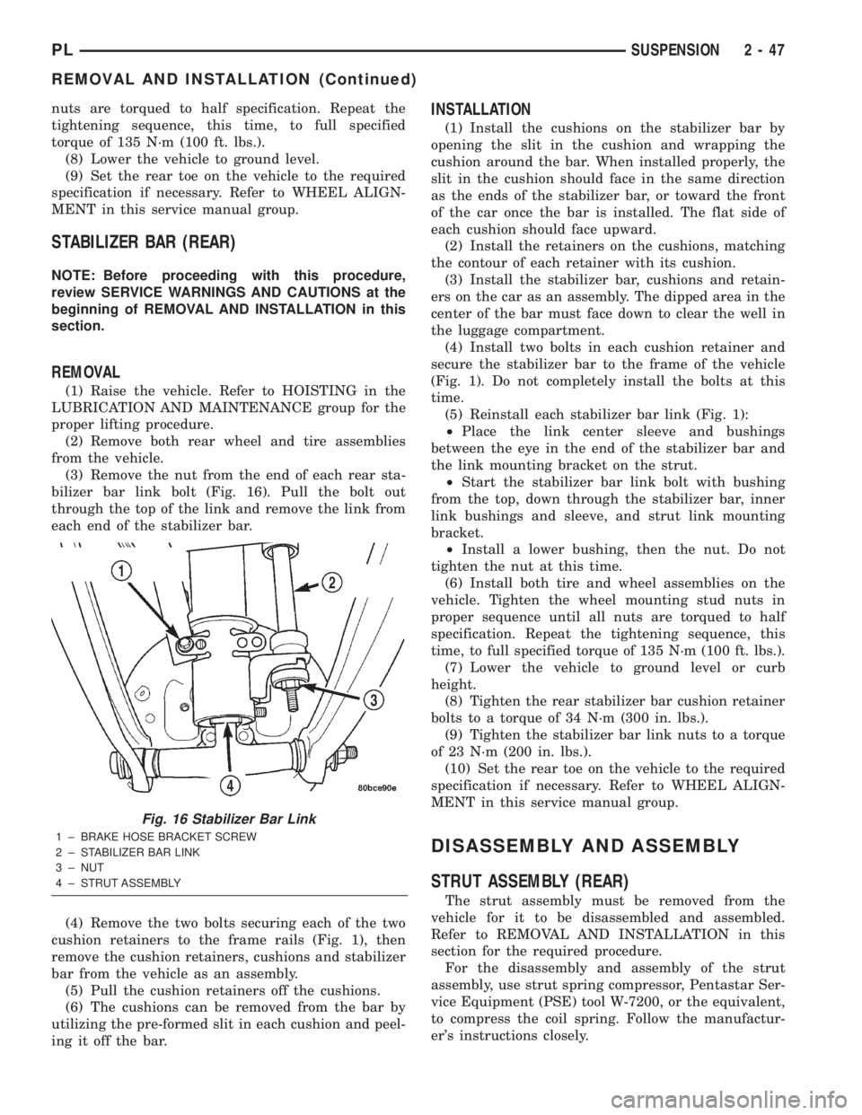
bilizer bar link bolt (Fig. 16). Pull the bolt out
through the top of the link and remove the link from
each end of the stabilizer bar.
(4) Remove the two bolts securing each of the two
cushion retainers to the frame rails (Fig. 1), then
remove the cushion retainers, cushions and stabilizer
bar from the vehicle as an assembly.
(5) Pull the cushion retainers off the cushions.
(6) The cushions can be removed from the bar by
utilizing the pre-formed slit in each cushion and peel-
ing it off the bar.
INSTALLATION
(1) Install the cushions on the stabilizer bar by
opening the slit in the cushion and wrapping the
cushion around the bar. When installed properly, the
slit in the cushion should face in the same direction
as the ends of the stabilizer bar, or toward the front
of the car once the bar is installed. The flat side of
each cushion should face upward.
(2) Install the retainers on the cushions, matching
the contour of each retainer with its cushion.
(3) Install the stabilizer bar, cushions and retain-
ers on the car as an assembly. The dipped area in the
center of the bar must face down to clear the well in
the luggage compartment.
(4) Install two bolts in each cushion retainer and
secure the stabilizer bar to the frame of the vehicle
(Fig. 1). Do not completely install the bolts at this
time.
(5) Reinstall each stabilizer bar link (Fig. 1):
²Place the link center sleeve and bushings
between the eye in the end of the stabilizer bar and
the link mounting bracket on the strut.
²Start the stabilizer bar link bolt with bushing
from the top, down through the stabilizer bar, inner
link bushings and sleeve, and strut link mounting
bracket.
²Install a lower bushing, then the nut. Do not
tighten the nut at this time.
(6) Install both tire and wheel assemblies on the
vehicle. Tighten the wheel mounting stud nuts in
proper sequence until all nuts are torqued to half
specification. Repeat the tightening sequence, this
time, to full specified torque of 135 N´m (100 ft. lbs.).
(7) Lower the vehicle to ground level or curb
height.
(8) Tighten the rear stabilizer bar cushion retainer
bolts to a torque of 34 N´m (300 in. lbs.).
(9) Tighten the stabilizer bar link nuts to a torque
of 23 N´m (200 in. lbs.).
(10) Set the rear toe on the vehicle to the required
specification if necessary. Refer to WHEEL ALIGN-
MENT in this service manual group.
DISASSEMBLY AND ASSEMBLY
STRUT ASSEMBLY (REAR)
The strut assembly must be removed from the
vehicle for it to be disassembled and assembled.
Refer to REMOVAL AND INSTALLATION in this
section for the required procedure.
For the disassembly and assembly of the strut
assembly, use strut spring compressor, Pentastar Ser-
vice Equipment (PSE) tool W-7200, or the equivalent,
to compress the coil spring. Follow the manufactur-
er's instructions closely.
Fig. 16 Stabilizer Bar Link
1 ± BRAKE HOSE BRACKET SCREW
2 ± STABILIZER BAR LINK
3 ± NUT
4 ± STRUT ASSEMBLY
PLSUSPENSION 2 - 47
REMOVAL AND INSTALLATION (Continued)
Page 61 of 1285
hex on the end of the strut shaft. While holding the
strut shaft from turning, tighten the strut shaft
retaining nut to a torque of 75 N´m (55 ft. lbs.).
(10) Slowly release the tension from the coil spring
by backing off the compressor drive completely. As
the tension is relieved, make sure the upper mount's
seat aligns properly with the coil spring.
(11) Verify the arrow on the upper mount is point-
ing in the same direction as the strut clevis bracket
as mentioned in step 9.
(12) Remove the clamp from the lower end of the
coil spring and strut. Push back the spring compres-
sor upper and lower hooks, then remove the strut
assembly from the spring compressor.
(13) Install the strut assembly on the vehicle.
Refer to REMOVAL AND INSTALLATION in this
section for the required procedure.
SPECIFICATIONS
REAR SUSPENSION FASTENER TORQUE
SPECIFICATIONS
DESCRIPTION TORQUE
STRUT ASSEMBLY:
Tower Attaching Nuts..... 34N´m(300 in. lbs.)
Knuckle Attaching Bolts.... 88N´m(65ft.lbs.)
Strut Assembly Shaft Nut . . . 75 N´m (55 ft. lbs.)
Brake Hose Bracket Mounting Bolt..... 31N´m
(275 in. lbs.)
KNUCKLE:
Brake Support Plate Mounting Bolts.... 75N´m
(55 ft. lbs.)
Disc Brake Adapter Mounting Bolts.... 75N´m
(55 ft. lbs.)
HUB AND BEARING:
To Knuckle Retaining Nut........... 217N´m
(160 ft. lbs.)
Wheel Mounting Nuts...........109-150 N´m
(80-110 ft. lbs.)
LATERAL ARM:
Nut At Crossmember....... 88N´m(65ft.lbs.)
Nut At Knuckle........... 95N´m(70ft.lbs.)
TENSION STRUT:
Rear Nut................ 95N´m(70ft.lbs.)
Frame Rail Bolts.......... 95N´m(70ft.lbs.)
Parking Brake Cable Nut . . 28 N´m (250 in. lbs.)
STABILIZER BAR:
Cushion Retainer Bolts.... 34N´m(300 in. lbs.)
Link Bolt Nut........... 23N´m(200 in. lbs.)
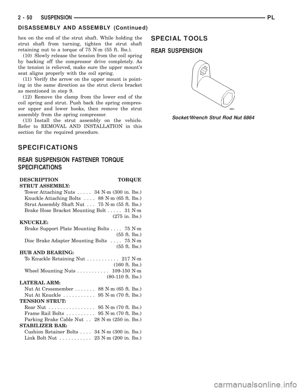
SPECIAL TOOLS
REAR SUSPENSION
Socket/Wrench Strut Rod Nut 6864
2 - 50 SUSPENSIONPL
DISASSEMBLY AND ASSEMBLY (Continued)