Page 1081 of 1285

pilot hole and bolt circle of the wheel should be the
same as the original wheel.
WARNING: FAILURE TO USE EQUIVALENT
REPLACEMENT WHEELS MAY ADVERSELY AFFECT
THE SAFETY AND HANDLING OF THE VEHICLE.
USED WHEELS ARE NOT RECOMMENDED. THE
SERVICE HISTORY OF THE WHEEL MAY HAVE
INCLUDED SEVERE TREATMENT OR VERY HIGH
MILEAGE. THE RIM COULD FAIL WITHOUT WARN-
ING.
TIRE AND WHEEL RUNOUT
NOTE: Runout should always be measured off the
vehicle and on a suitable balance machine.
Radial run out is the difference between the high
and low points on the outer edge of the tire or wheel.
Lateral run out is the total side±to±side wobble of
the tire or wheel.
Radial run out of more than 1.5 mm (.060 inch)
measured at the center line of the tread may cause
the vehicle to shake.
Lateral run out of more than 2.0 mm (.080 inch)
measured at the side of the tire as close to the tread
as possible may cause the vehicle to shake.
Sometimes radial run out can be reduced by relo-
cating the wheel and tire on the wheel studs (See
Method 1). If this does not reduce run out to an
acceptable level, the tire can be rotated on the wheel.
(See Method 2).
METHOD 1 (RELOCATE WHEEL ON HUB)
Check accuracy of the wheel mounting surface;
adjust wheel bearings.
Drive vehicle a short distance to eliminate tire flat
spotting from a parked position.
Verify all wheel nuts are tightened and properly
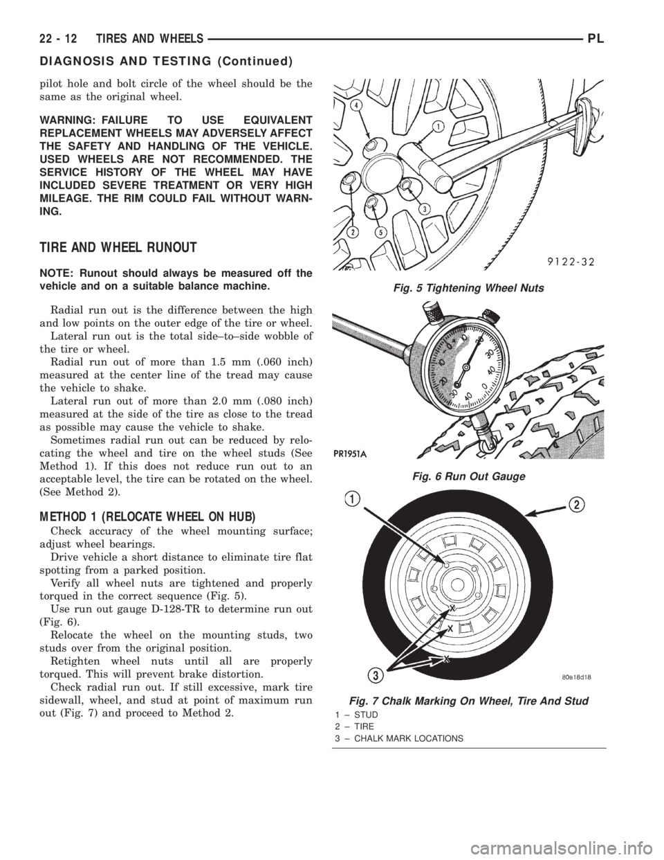
torqued in the correct sequence (Fig. 5).
Use run out gauge D-128-TR to determine run out
(Fig. 6).
Relocate the wheel on the mounting studs, two
studs over from the original position.
Retighten wheel nuts until all are properly
torqued. This will prevent brake distortion.
Check radial run out. If still excessive, mark tire
sidewall, wheel, and stud at point of maximum run
out (Fig. 7) and proceed to Method 2.
Fig. 5 Tightening Wheel Nuts
Fig. 6 Run Out Gauge
Fig. 7 Chalk Marking On Wheel, Tire And Stud
1 ± STUD
2 ± TIRE
3 ± CHALK MARK LOCATIONS
22 - 12 TIRES AND WHEELSPL
DIAGNOSIS AND TESTING (Continued)
Page 1268 of 1285

HEATING AND AIR CONDITIONING
TABLE OF CONTENTS
page page
REMOVAL AND INSTALLATION
EVAPORATOR CORE ± R. H. D...............1
HEATER CORE ± R. H. D....................3SPECIFICATIONS
TORQUE SPECIFICATIONS..................6
REMOVAL AND INSTALLATION
EVAPORATOR CORE ± R. H. D.
REMOVAL
WARNING: ON VEHICLES EQUIPPED WITH AIR-
BAGS, REFER TO GROUP 8M ± PASSIVE
RESTRAINT SYSTEMS BEFORE ATTEMPTING ANY
STEERING WHEEL, STEERING COLUMN, OR
INSTRUMENT PANEL COMPONENT DIAGNOSIS OR
SERVICE. FAILURE TO TAKE THE PROPER PRE-
CAUTIONS COULD RESULT IN ACCIDENTAL AIR-
BAG DEPLOYMENT AND POSSIBLE PERSONAL
INJURY.
WARNING: DO NOT OPEN THE RADIATOR DRAIN-
COCK OR DISCONNECT COOLANT HOSES WHEN
THE COOLING SYSTEM IS HOT AND UNDER PRES-
SURE. SERIOUS BURNS FROM COOLANT CAN
OCCUR.
WARNING: READ ALL SAFETY PRECAUTIONS AND
WARNINGS BEFORE PROCEEDING WITH THIS
OPERATION.
(1) Disconnect the negative battery cable.
(2) Drain the cooling system. Refer to Group 7,
Cooling System for the procedure.
(3) Evacuate the refrigerant system.
(4) Remove the instrument panel. Refer to Group
8E, Instrument Panel and Systems for the procedure.
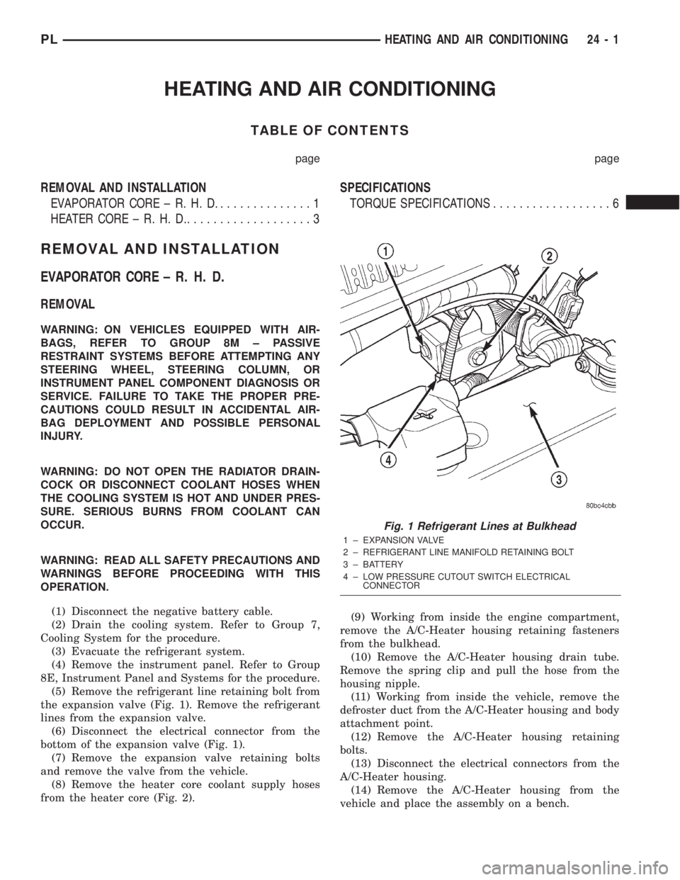
(5) Remove the refrigerant line retaining bolt from
the expansion valve (Fig. 1). Remove the refrigerant
lines from the expansion valve.
(6) Disconnect the electrical connector from the
bottom of the expansion valve (Fig. 1).
(7) Remove the expansion valve retaining bolts
and remove the valve from the vehicle.
(8) Remove the heater core coolant supply hoses
from the heater core (Fig. 2).(9) Working from inside the engine compartment,
remove the A/C-Heater housing retaining fasteners
from the bulkhead.
(10) Remove the A/C-Heater housing drain tube.
Remove the spring clip and pull the hose from the
housing nipple.
(11) Working from inside the vehicle, remove the
defroster duct from the A/C-Heater housing and body
attachment point.
(12) Remove the A/C-Heater housing retaining
bolts.
(13) Disconnect the electrical connectors from the
A/C-Heater housing.
(14) Remove the A/C-Heater housing from the
vehicle and place the assembly on a bench.
Fig. 1 Refrigerant Lines at Bulkhead
1 ± EXPANSION VALVE
2 ± REFRIGERANT LINE MANIFOLD RETAINING BOLT
3 ± BATTERY
4 ± LOW PRESSURE CUTOUT SWITCH ELECTRICAL
CONNECTOR
PLHEATING AND AIR CONDITIONING 24 - 1
Page 1270 of 1285

(7) Install the A/C-Heater housing retaining fas-
teners. Torque the fasteners to 20 N´m (177 in. lbs.).
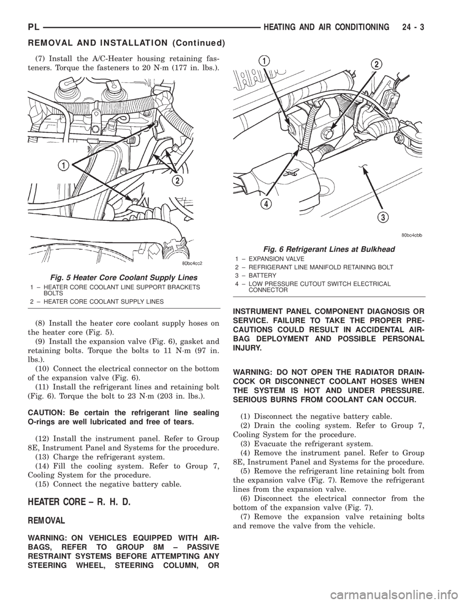
(8) Install the heater core coolant supply hoses on
the heater core (Fig. 5).
(9) Install the expansion valve (Fig. 6), gasket and
retaining bolts. Torque the bolts to 11 N´m (97 in.
lbs.).
(10) Connect the electrical connector on the bottom
of the expansion valve (Fig. 6).
(11) Install the refrigerant lines and retaining bolt
(Fig. 6). Torque the bolt to 23 N´m (203 in. lbs.).
CAUTION: Be certain the refrigerant line sealing
O-rings are well lubricated and free of tears.
(12) Install the instrument panel. Refer to Group
8E, Instrument Panel and Systems for the procedure.
(13) Charge the refrigerant system.
(14) Fill the cooling system. Refer to Group 7,
Cooling System for the procedure.
(15) Connect the negative battery cable.
HEATER CORE ± R. H. D.
REMOVAL
WARNING: ON VEHICLES EQUIPPED WITH AIR-
BAGS, REFER TO GROUP 8M ± PASSIVE
RESTRAINT SYSTEMS BEFORE ATTEMPTING ANY
STEERING WHEEL, STEERING COLUMN, ORINSTRUMENT PANEL COMPONENT DIAGNOSIS OR
SERVICE. FAILURE TO TAKE THE PROPER PRE-
CAUTIONS COULD RESULT IN ACCIDENTAL AIR-
BAG DEPLOYMENT AND POSSIBLE PERSONAL
INJURY.
WARNING: DO NOT OPEN THE RADIATOR DRAIN-
COCK OR DISCONNECT COOLANT HOSES WHEN
THE SYSTEM IS HOT AND UNDER PRESSURE.
SERIOUS BURNS FROM COOLANT CAN OCCUR.
(1) Disconnect the negative battery cable.
(2) Drain the cooling system. Refer to Group 7,
Cooling System for the procedure.
(3) Evacuate the refrigerant system.
(4) Remove the instrument panel. Refer to Group
8E, Instrument Panel and Systems for the procedure.
(5) Remove the refrigerant line retaining bolt from
the expansion valve (Fig. 7). Remove the refrigerant
lines from the expansion valve.
(6) Disconnect the electrical connector from the
bottom of the expansion valve (Fig. 7).
(7) Remove the expansion valve retaining bolts
and remove the valve from the vehicle.
Fig. 5 Heater Core Coolant Supply Lines
1 ± HEATER CORE COOLANT LINE SUPPORT BRACKETS
BOLTS
2 ± HEATER CORE COOLANT SUPPLY LINES
Fig. 6 Refrigerant Lines at Bulkhead
1 ± EXPANSION VALVE
2 ± REFRIGERANT LINE MANIFOLD RETAINING BOLT
3 ± BATTERY
4 ± LOW PRESSURE CUTOUT SWITCH ELECTRICAL
CONNECTOR
PLHEATING AND AIR CONDITIONING 24 - 3
REMOVAL AND INSTALLATION (Continued)