2000 DODGE NEON headlamp
[x] Cancel search: headlampPage 332 of 1285
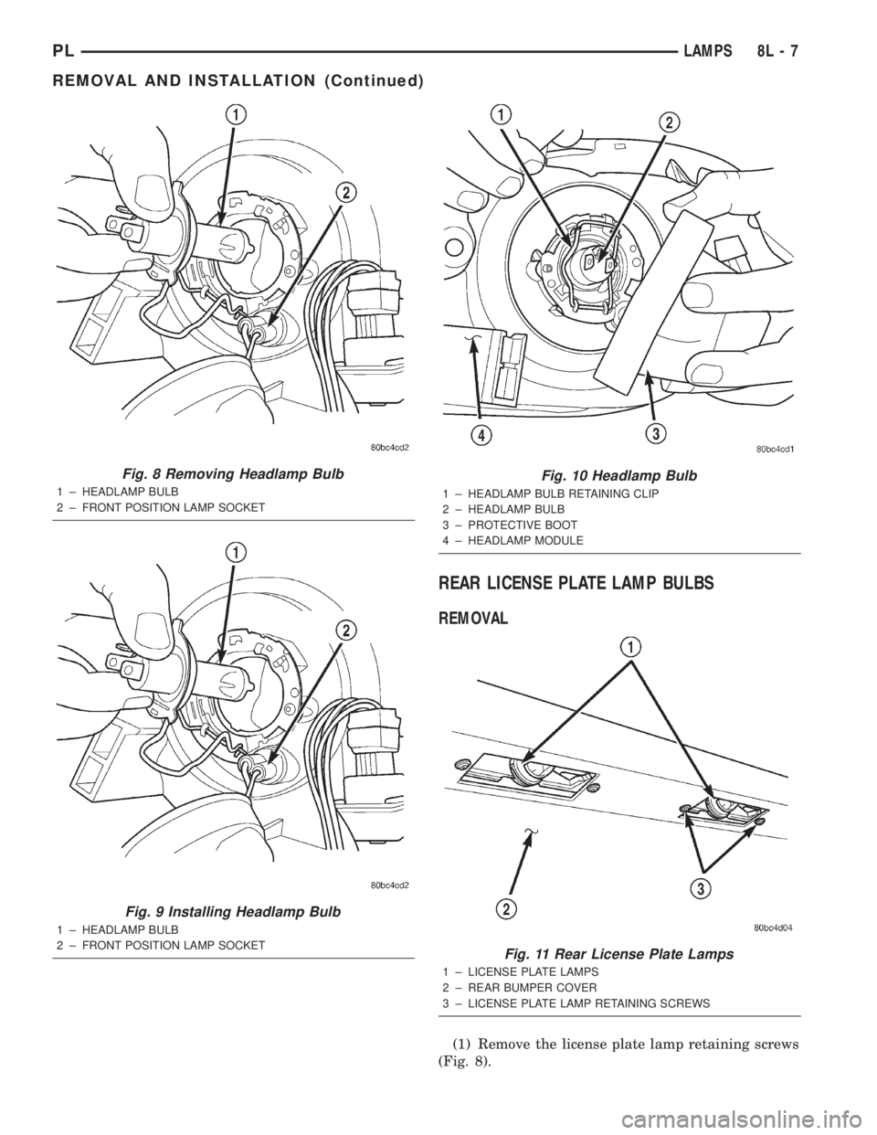
REAR LICENSE PLATE LAMP BULBS
REMOVAL
(1) Remove the license plate lamp retaining screws
(Fig. 8).
Fig. 8 Removing Headlamp Bulb
1 ± HEADLAMP BULB
2 ± FRONT POSITION LAMP SOCKET
Fig. 9 Installing Headlamp Bulb
1 ± HEADLAMP BULB
2 ± FRONT POSITION LAMP SOCKET
Fig. 10 Headlamp Bulb
1 ± HEADLAMP BULB RETAINING CLIP
2 ± HEADLAMP BULB
3 ± PROTECTIVE BOOT
4 ± HEADLAMP MODULE
Fig. 11 Rear License Plate Lamps
1 ± LICENSE PLATE LAMPS
2 ± REAR BUMPER COVER
3 ± LICENSE PLATE LAMP RETAINING SCREWS
PLLAMPS 8L - 7
REMOVAL AND INSTALLATION (Continued)
Page 337 of 1285
LAMP SERVICE
TABLE OF CONTENTS
page page
GENERAL INFORMATION
HEADLAMP SWITCH......................12
HEADLAMP LEVELING SWITCH.............12
HEADLAMP DIMMER SWITCH...............12
REMOVAL AND INSTALLATION
CENTER HIGH MOUNTED STOP LAMP
(CHMSL)..............................12HEADLAMP MODULE.....................12
HEADLAMP LEVELING MOTOR..............14
FRONT FOG LAMP.......................15
REAR LICENSE PLATE LAMPS..............15
REAR FOG LAMP........................15
SIDE REPEATER LAMP....................17
TAIL, STOP AND TURN SIGNAL LAMP........18
GENERAL INFORMATION
HEADLAMP SWITCH
Service procedures for the headlamp switch can be
found in Group 8E, Instrument Panel and Gauges.
More information can be found in Group 8W, Wiring
Diagrams.
HEADLAMP LEVELING SWITCH
Service procedures for the headlamp leveling
switch can be found in Group 8E, Instrument Panel
Systems. More information can be found in Group
8W, Wiring Diagrams.
HEADLAMP DIMMER SWITCH
The headlamp dimmer switch is incorporated into
the multi-function (turn signal) switch. Proper proce-
dures can be found in Group 8J, Turn Signal and
Flashers. More information can be found in Group
8W, Wiring Diagrams.
REMOVAL AND INSTALLATION
CENTER HIGH MOUNTED STOP LAMP
(CHMSL)
REMOVAL
(1) Open the trunklid
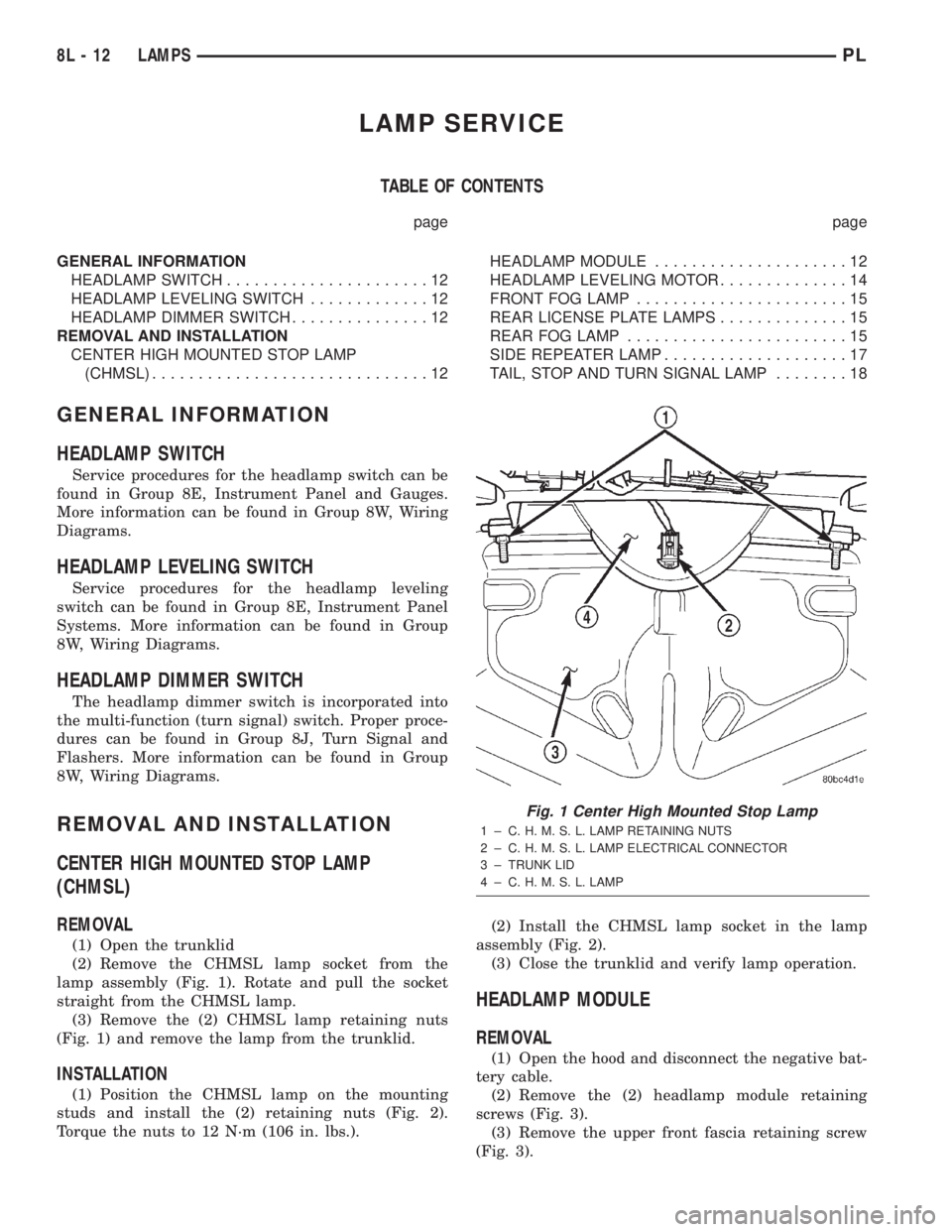
(2) Remove the CHMSL lamp socket from the
lamp assembly (Fig. 1). Rotate and pull the socket
straight from the CHMSL lamp.
(3) Remove the (2) CHMSL lamp retaining nuts
(Fig. 1) and remove the lamp from the trunklid.
INSTALLATION
(1) Position the CHMSL lamp on the mounting
studs and install the (2) retaining nuts (Fig. 2).
Torque the nuts to 12 N´m (106 in. lbs.).(2) Install the CHMSL lamp socket in the lamp
assembly (Fig. 2).
(3) Close the trunklid and verify lamp operation.
HEADLAMP MODULE
REMOVAL
(1) Open the hood and disconnect the negative bat-
tery cable.
(2) Remove the (2) headlamp module retaining
screws (Fig. 3).
(3) Remove the upper front fascia retaining screw
(Fig. 3).
Fig. 1 Center High Mounted Stop Lamp
1 ± C. H. M. S. L. LAMP RETAINING NUTS
2 ± C. H. M. S. L. LAMP ELECTRICAL CONNECTOR
3 ± TRUNK LID
4 ± C. H. M. S. L. LAMP
8L - 12 LAMPSPL
Page 338 of 1285
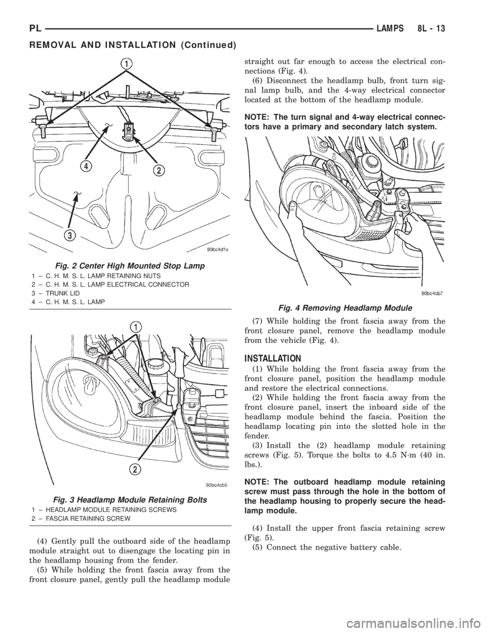
(4) Gently pull the outboard side of the headlamp
module straight out to disengage the locating pin in
the headlamp housing from the fender.
(5) While holding the front fascia away from the
front closure panel, gently pull the headlamp modulestraight out far enough to access the electrical con-
nections (Fig. 4).
(6) Disconnect the headlamp bulb, front turn sig-
nal lamp bulb, and the 4-way electrical connector
located at the bottom of the headlamp module.
NOTE: The turn signal and 4-way electrical connec-
tors have a primary and secondary latch system.
(7) While holding the front fascia away from the
front closure panel, remove the headlamp module
from the vehicle (Fig. 4).
INSTALLATION
(1) While holding the front fascia away from the
front closure panel, position the headlamp module
and restore the electrical connections.
(2) While holding the front fascia away from the
front closure panel, insert the inboard side of the
headlamp module behind the fascia. Position the
headlamp locating pin into the slotted hole in the
fender.
(3) Install the (2) headlamp module retaining
screws (Fig. 5). Torque the bolts to 4.5 N´m (40 in.
lbs.).
NOTE: The outboard headlamp module retaining
screw must pass through the hole in the bottom of
the headlamp housing to properly secure the head-
lamp module.
(4) Install the upper front fascia retaining screw
(Fig. 5).
(5) Connect the negative battery cable.
Fig. 2 Center High Mounted Stop Lamp
1 ± C. H. M. S. L. LAMP RETAINING NUTS
2 ± C. H. M. S. L. LAMP ELECTRICAL CONNECTOR
3 ± TRUNK LID
4 ± C. H. M. S. L. LAMP
Fig. 3 Headlamp Module Retaining Bolts
1 ± HEADLAMP MODULE RETAINING SCREWS
2 ± FASCIA RETAINING SCREW
Fig. 4 Removing Headlamp Module
PLLAMPS 8L - 13
REMOVAL AND INSTALLATION (Continued)
Page 339 of 1285
HEADLAMP LEVELING MOTOR
REMOVAL
(1) Remove the appropriate headlamp module from
the vehicle. Refer to the HEADLAMP MODULE
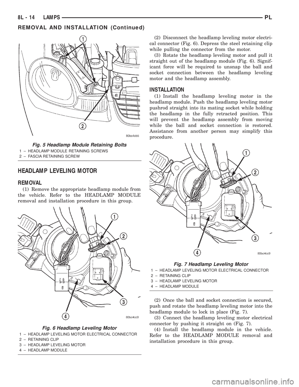
removal and installation procedure in this group.(2) Disconnect the headlamp leveling motor electri-
cal connector (Fig. 6). Depress the steel retaining clip
while pulling the connector from the motor.
(3) Rotate the headlamp leveling motor and pull it
straight out of the headlamp module (Fig. 6). Signif-
icant force will be required to unsnap the ball and
socket connection between the headlamp leveling
motor and the headlamp assembly.
INSTALLATION
(1) Install the headlamp leveling motor in the
headlamp module. Push the headlamp leveling motor
pushrod straight into its mating socket while holding
the headlamp in the fully retracted position. This
will prevent the headlamp assembly from moving
while the ball and socket connection is restored.
Assistance from another person may simplify this
procedure.
(2) Once the ball and socket connection is secured,
push and rotate the headlamp leveling motor into the
headlamp module to lock in place (Fig. 7).
(3) Connect the headlamp leveling motor electrical
connector by pushing it straight on (Fig. 7).
(4) Install the headlamp module in the vehicle.
Refer to the HEADLAMP MODULE removal and
installation procedure in this group.
Fig. 5 Headlamp Module Retaining Bolts
1 ± HEADLAMP MODULE RETAINING SCREWS
2 ± FASCIA RETAINING SCREW
Fig. 6 Headlamp Leveling Motor
1 ± HEADLAMP LEVELING MOTOR ELECTRICAL CONNECTOR
2 ± RETAINING CLIP
3 ± HEADLAMP LEVELING MOTOR
4 ± HEADLAMP MODULE
Fig. 7 Headlamp Leveling Motor
1 ± HEADLAMP LEVELING MOTOR ELECTRICAL CONNECTOR
2 ± RETAINING CLIP
3 ± HEADLAMP LEVELING MOTOR
4 ± HEADLAMP MODULE
8L - 14 LAMPSPL
REMOVAL AND INSTALLATION (Continued)
Page 344 of 1285
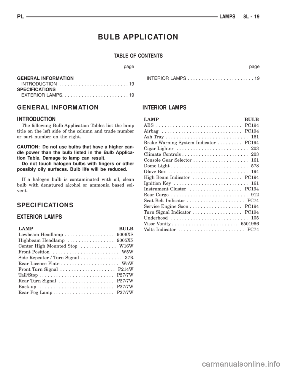
BULB APPLICATION
TABLE OF CONTENTS
page page
GENERAL INFORMATION
INTRODUCTION.........................19
SPECIFICATIONS
EXTERIOR LAMPS........................19INTERIOR LAMPS........................19
GENERAL INFORMATION
INTRODUCTION
The following Bulb Application Tables list the lamp
title on the left side of the column and trade number
or part number on the right.
CAUTION: Do not use bulbs that have a higher can-
dle power than the bulb listed in the Bulb Applica-
tion Table. Damage to lamp can result.
Do not touch halogen bulbs with fingers or other
possibly oily surfaces. Bulb life will be reduced.
If a halogen bulb is contaminated with oil, clean
bulb with denatured alcohol or ammonia based sol-
vent.
SPECIFICATIONS
EXTERIOR LAMPS
LAMP BULB
Lowbeam Headlamp..................9006XS
Highbeam Headlamp.................9005XS
Center High Mounted Stop.............W16W
Front Position........................ W5W
Side Repeater / Turn Signal............... 37R
Rear License Plate..................... W5W
Front Turn Signal....................P214W
Tail/Stop...........................P27/7W
Rear Turn Signal....................P27/7W
Back-up...........................P27/7W
Rear Fog Lamp......................P27/7W
INTERIOR LAMPS
LAMP BULB
ABS ...............................PC194
Airbag.............................PC194
AshTray .............................. 161
Brake Warning System Indicator.........PC194
Cigar Lighter.......................... 203
Climate Controls........................ 203
Console Gear Selector.................... 161
Dome Light............................ 578
Glove Box............................. 194
High Beam Indicator..................PC194
Ignition Key........................... 161
Instrument Cluster...................PC194
Rear Cargo............................ 912
Seat Belt Indicator.....................PC74
Service Engine Soon...................PC194
Turn Signal Indicator..................PC194
Underhood............................ 105
Visor Vanity........................6501966
Volts Indicator........................PC74
PLLAMPS 8L - 19
Page 372 of 1285
VEHICLE THEFT/SECURITY SYSTEM
TABLE OF CONTENTS
page page
DESCRIPTION AND OPERATION
INTRODUCTION..........................1
VEHICLE THEFT/SECURITY SYSTEM (VTSS)...1
SENTRY KEY IMMOBILIZER SYSTEM (SKIS)...2
SENTRY KEY IMMOBILIZER MODULE
(SKIM)................................2
SENTRY KEY IMMOBILIZER SYSTEM
TRANSPONDER.........................3
SENTRY KEY IMMOBILIZER SYSTEM
INDICATOR LAMP.......................4
TRIGGERING THE VTSS....................4
DIAGNOSIS AND TESTING
SENTRY KEY IMMOBILIZER SYSTEM.........4
VEHICLE THEFT/SECURITY SYSTEM (VTSS)...5SERVICE PROCEDURES
SENTRY KEY IMMOBILIZER SYSTEM
INITIALIZATION.........................5
SENTRY KEY IMMOBILIZER SYSTEM
TRANSPONDER PROGRAMMING...........5
SWITCHING OPERATING MODES/
CONFIGURING A NEW MODULE............6
REMOVAL AND INSTALLATION
DOOR CYLINDER LOCK SWITCH.............7
HOOD AJAR SWITCH......................7
SENTRY KEY IMMOBILIZER MODULE
(SKIM)................................7
VEHICLE THEFT/SECURITY SYSTEM DECK
LID SECURITY (KNOCK OUT) SWITCH.......8
DESCRIPTION AND OPERATION
INTRODUCTION
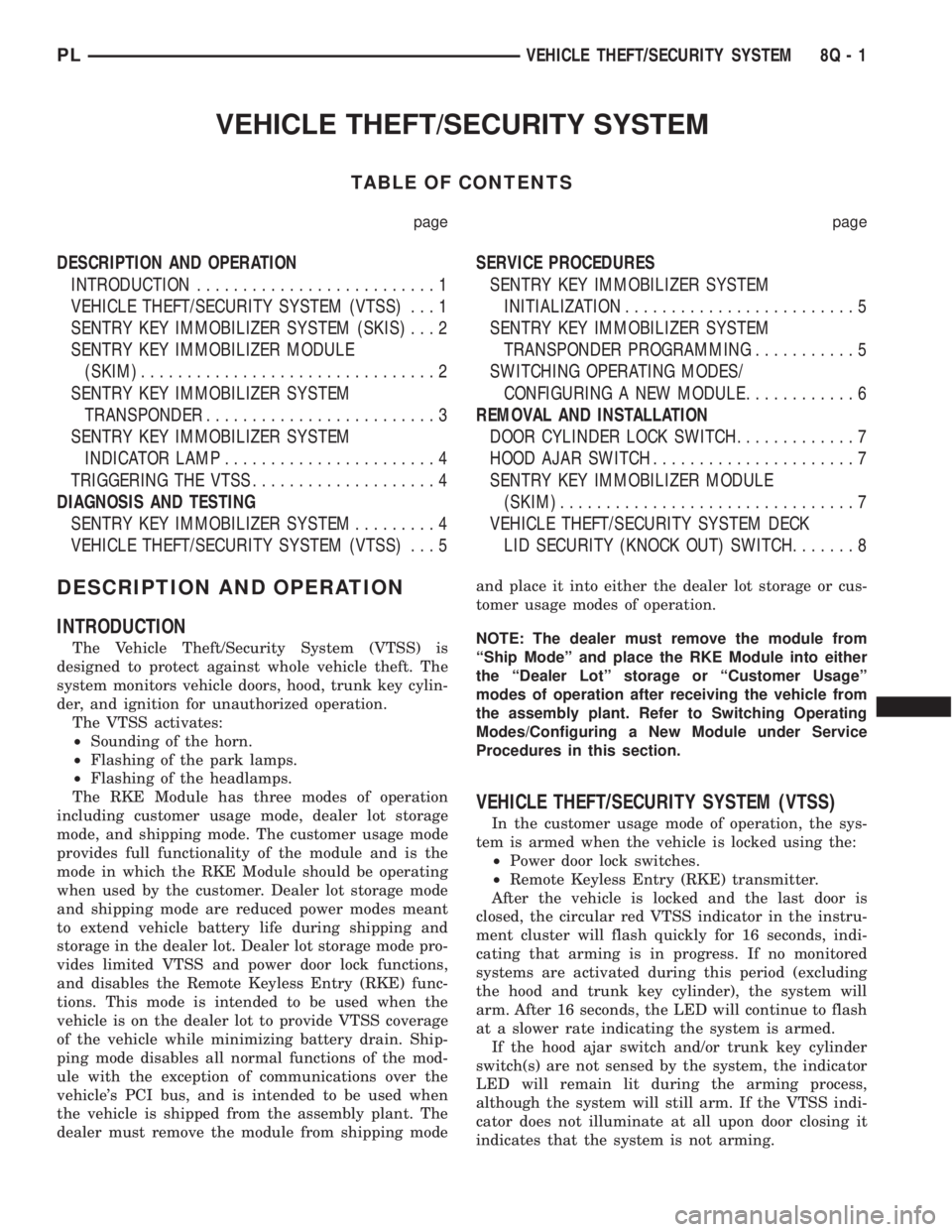
The Vehicle Theft/Security System (VTSS) is
designed to protect against whole vehicle theft. The
system monitors vehicle doors, hood, trunk key cylin-
der, and ignition for unauthorized operation.
The VTSS activates:
²Sounding of the horn.
²Flashing of the park lamps.
²Flashing of the headlamps.
The RKE Module has three modes of operation
including customer usage mode, dealer lot storage
mode, and shipping mode. The customer usage mode
provides full functionality of the module and is the
mode in which the RKE Module should be operating
when used by the customer. Dealer lot storage mode
and shipping mode are reduced power modes meant
to extend vehicle battery life during shipping and
storage in the dealer lot. Dealer lot storage mode pro-
vides limited VTSS and power door lock functions,
and disables the Remote Keyless Entry (RKE) func-
tions. This mode is intended to be used when the
vehicle is on the dealer lot to provide VTSS coverage
of the vehicle while minimizing battery drain. Ship-
ping mode disables all normal functions of the mod-
ule with the exception of communications over the
vehicle's PCI bus, and is intended to be used when
the vehicle is shipped from the assembly plant. The
dealer must remove the module from shipping modeand place it into either the dealer lot storage or cus-
tomer usage modes of operation.
NOTE: The dealer must remove the module from
ªShip Modeº and place the RKE Module into either
the ªDealer Lotº storage or ªCustomer Usageº
modes of operation after receiving the vehicle from
the assembly plant. Refer to Switching Operating
Modes/Configuring a New Module under Service
Procedures in this section.
VEHICLE THEFT/SECURITY SYSTEM (VTSS)
In the customer usage mode of operation, the sys-
tem is armed when the vehicle is locked using the:
²Power door lock switches.
²Remote Keyless Entry (RKE) transmitter.
After the vehicle is locked and the last door is
closed, the circular red VTSS indicator in the instru-
ment cluster will flash quickly for 16 seconds, indi-
cating that arming is in progress. If no monitored
systems are activated during this period (excluding
the hood and trunk key cylinder), the system will
arm. After 16 seconds, the LED will continue to flash
at a slower rate indicating the system is armed.
If the hood ajar switch and/or trunk key cylinder
switch(s) are not sensed by the system, the indicator
LED will remain lit during the arming process,
although the system will still arm. If the VTSS indi-
cator does not illuminate at all upon door closing it
indicates that the system is not arming.
PLVEHICLE THEFT/SECURITY SYSTEM 8Q - 1
Page 390 of 1285
CHIME WARNING/REMINDER SYSTEM
TABLE OF CONTENTS
page page
DESCRIPTION AND OPERATION
INTRODUCTION..........................1
DIAGNOSIS AND TESTING
FASTEN SEAT BELTS......................1
HEADLAMPS LEFT ON.....................1
KEY LEFT IN IGNITION SWITCH.............1CHIME SYSTEM CONDITIONS...............1
REMOVAL AND INSTALLATION
CHIME..................................2
SEAT BELT BUCKLE.......................2
HEADLAMP SWITCH......................2
KEY-IN SWITCH..........................2
DESCRIPTION AND OPERATION
INTRODUCTION
WARNING: ON VEHICLES EQUIPPED WITH AN AIR-
BAG, REFER TO THE AIRBAG PORTION OF THIS
SECTION FOR STEERING WHEEL OR SWITCH
REMOVAL AND INSTALLATION PROCEDURES.
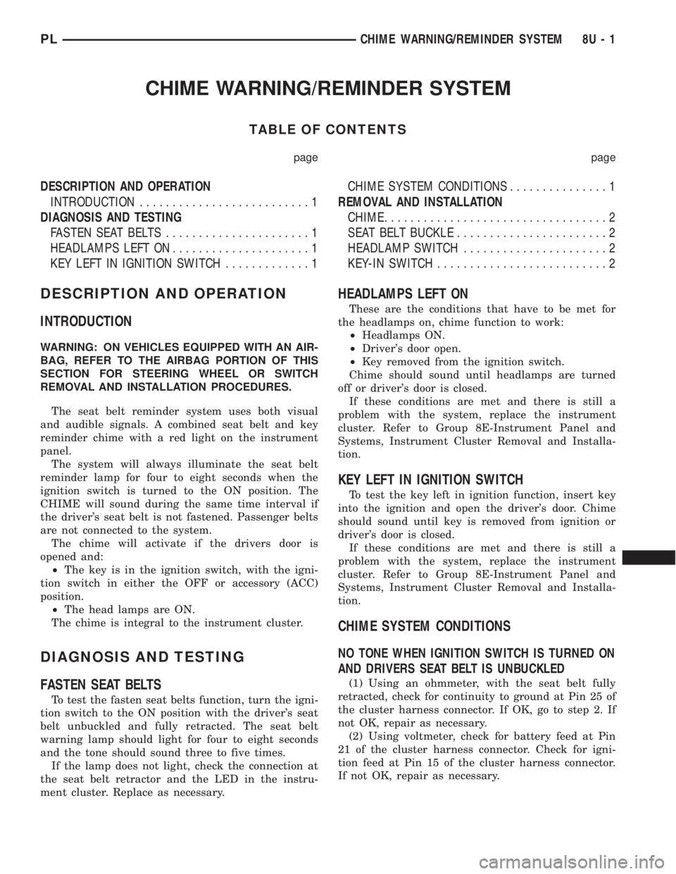
The seat belt reminder system uses both visual
and audible signals. A combined seat belt and key
reminder chime with a red light on the instrument
panel.
The system will always illuminate the seat belt
reminder lamp for four to eight seconds when the
ignition switch is turned to the ON position. The
CHIME will sound during the same time interval if
the driver's seat belt is not fastened. Passenger belts
are not connected to the system.
The chime will activate if the drivers door is
opened and:
²The key is in the ignition switch, with the igni-
tion switch in either the OFF or accessory (ACC)
position.
²The head lamps are ON.
The chime is integral to the instrument cluster.
DIAGNOSIS AND TESTING
FASTEN SEAT BELTS
To test the fasten seat belts function, turn the igni-
tion switch to the ON position with the driver's seat
belt unbuckled and fully retracted. The seat belt
warning lamp should light for four to eight seconds
and the tone should sound three to five times.
If the lamp does not light, check the connection at
the seat belt retractor and the LED in the instru-
ment cluster. Replace as necessary.
HEADLAMPS LEFT ON
These are the conditions that have to be met for
the headlamps on, chime function to work:
²Headlamps ON.
²Driver's door open.
²Key removed from the ignition switch.
Chime should sound until headlamps are turned
off or driver's door is closed.
If these conditions are met and there is still a
problem with the system, replace the instrument
cluster. Refer to Group 8E-Instrument Panel and
Systems, Instrument Cluster Removal and Installa-
tion.
KEY LEFT IN IGNITION SWITCH
To test the key left in ignition function, insert key
into the ignition and open the driver's door. Chime
should sound until key is removed from ignition or
driver's door is closed.
If these conditions are met and there is still a
problem with the system, replace the instrument
cluster. Refer to Group 8E-Instrument Panel and
Systems, Instrument Cluster Removal and Installa-
tion.
CHIME SYSTEM CONDITIONS
NO TONE WHEN IGNITION SWITCH IS TURNED ON
AND DRIVERS SEAT BELT IS UNBUCKLED
(1) Using an ohmmeter, with the seat belt fully
retracted, check for continuity to ground at Pin 25 of
the cluster harness connector. If OK, go to step 2. If
not OK, repair as necessary.
(2) Using voltmeter, check for battery feed at Pin
21 of the cluster harness connector. Check for igni-
tion feed at Pin 15 of the cluster harness connector.
If not OK, repair as necessary.
PLCHIME WARNING/REMINDER SYSTEM 8U - 1
Page 391 of 1285
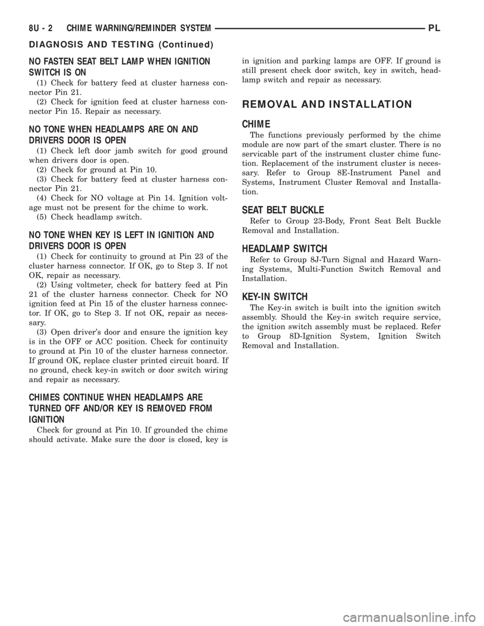
NO FASTEN SEAT BELT LAMP WHEN IGNITION
SWITCH IS ON
(1) Check for battery feed at cluster harness con-
nector Pin 21.
(2) Check for ignition feed at cluster harness con-
nector Pin 15. Repair as necessary.
NO TONE WHEN HEADLAMPS ARE ON AND
DRIVERS DOOR IS OPEN
(1) Check left door jamb switch for good ground
when drivers door is open.
(2) Check for ground at Pin 10.
(3) Check for battery feed at cluster harness con-
nector Pin 21.
(4) Check for NO voltage at Pin 14. Ignition volt-
age must not be present for the chime to work.
(5) Check headlamp switch.
NO TONE WHEN KEY IS LEFT IN IGNITION AND
DRIVERS DOOR IS OPEN
(1) Check for continuity to ground at Pin 23 of the
cluster harness connector. If OK, go to Step 3. If not
OK, repair as necessary.
(2) Using voltmeter, check for battery feed at Pin
21 of the cluster harness connector. Check for NO
ignition feed at Pin 15 of the cluster harness connec-
tor. If OK, go to Step 3. If not OK, repair as neces-
sary.
(3) Open driver's door and ensure the ignition key
is in the OFF or ACC position. Check for continuity
to ground at Pin 10 of the cluster harness connector.
If ground OK, replace cluster printed circuit board. If
no ground, check key-in switch or door switch wiring
and repair as necessary.
CHIMES CONTINUE WHEN HEADLAMPS ARE
TURNED OFF AND/OR KEY IS REMOVED FROM
IGNITION
Check for ground at Pin 10. If grounded the chime
should activate. Make sure the door is closed, key isin ignition and parking lamps are OFF. If ground is
still present check door switch, key in switch, head-
lamp switch and repair as necessary.
REMOVAL AND INSTALLATION
CHIME
The functions previously performed by the chime
module are now part of the smart cluster. There is no
servicable part of the instrument cluster chime func-
tion. Replacement of the instrument cluster is neces-
sary. Refer to Group 8E-Instrument Panel and
Systems, Instrument Cluster Removal and Installa-
tion.
SEAT BELT BUCKLE
Refer to Group 23-Body, Front Seat Belt Buckle
Removal and Installation.
HEADLAMP SWITCH
Refer to Group 8J-Turn Signal and Hazard Warn-
ing Systems, Multi-Function Switch Removal and
Installation.
KEY-IN SWITCH
The Key-in switch is built into the ignition switch
assembly. Should the Key-in switch require service,
the ignition switch assembly must be replaced. Refer
to Group 8D-Ignition System, Ignition Switch
Removal and Installation.
8U - 2 CHIME WARNING/REMINDER SYSTEMPL
DIAGNOSIS AND TESTING (Continued)