2000 DODGE NEON engine coolant
[x] Cancel search: engine coolantPage 200 of 1285
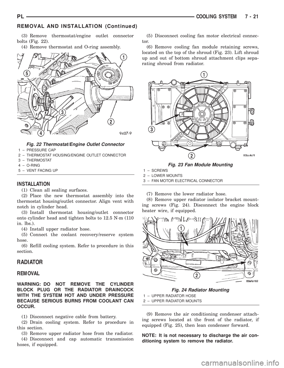
(3) Remove thermostat/engine outlet connector
bolts (Fig. 22).
(4) Remove thermostat and O-ring assembly.
INSTALLATION
(1) Clean all sealing surfaces.
(2) Place the new thermostat assembly into the
thermostat housing/outlet connector. Align vent with
notch in cylinder head.
(3) Install thermostat housing/outlet connector
onto cylinder head and tighten bolts to 12.5 N´m (110
in. lbs.).
(4) Install upper radiator hose.
(5) Connect the coolant recovery/reserve system
hose.
(6) Refill cooling system. Refer to procedure in this
section.
RADIATOR
REMOVAL
WARNING: DO NOT REMOVE THE CYLINDER
BLOCK PLUG OR THE RADIATOR DRAINCOCK
WITH THE SYSTEM HOT AND UNDER PRESSURE
BECAUSE SERIOUS BURNS FROM COOLANT CAN
OCCUR.
(1) Disconnect negative cable from battery.
(2) Drain cooling system. Refer to procedure in
this section.
(3) Remove upper radiator hose from the radiator.
(4) Disconnect and cap automatic transmission
hoses, if equipped.(5) Disconnect cooling fan motor electrical connec-
tor.
(6) Remove cooling fan module retaining screws,
located on the top of the shroud (Fig. 23). Lift shroud
up and out of bottom shroud attachment clips sepa-
rating shroud from radiator.
(7) Remove the lower radiator hose.
(8) Remove upper radiator isolator bracket mount-
ing screws (Fig. 24). Disconnect the engine block
heater wire, if equipped.
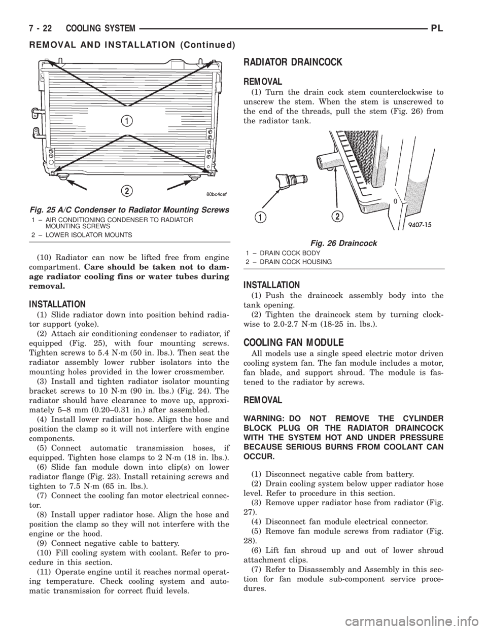
(9) Remove the air conditioning condenser attach-
ing screws located at the front of the radiator, if
equipped (Fig. 25), then lean condenser forward.
NOTE: It is not necessary to discharge the air con-
ditioning system to remove the radiator.
Fig. 22 Thermostat/Engine Outlet Connector
1 ± PRESSURE CAP
2 ± THERMOSTAT HOUSING/ENGINE OUTLET CONNECTOR
3 ± THERMOSTAT
4 ± O-RING
5 ± VENT FACING UP
Fig. 23 Fan Module Mounting
1 ± SCREWS
2 ± LOWER MOUNTS
3 ± FAN MOTOR ELECTRICAL CONNECTOR
Fig. 24 Radiator Mounting
1 ± UPPER RADIATOR HOSE
2 ± UPPER RADIATOR MOUNTS
PLCOOLING SYSTEM 7 - 21
REMOVAL AND INSTALLATION (Continued)
Page 201 of 1285
(10) Radiator can now be lifted free from engine
compartment.Care should be taken not to dam-
age radiator cooling fins or water tubes during
removal.
INSTALLATION
(1) Slide radiator down into position behind radia-
tor support (yoke).
(2) Attach air conditioning condenser to radiator, if
equipped (Fig. 25), with four mounting screws.
Tighten screws to 5.4 N´m (50 in. lbs.). Then seat the
radiator assembly lower rubber isolators into the
mounting holes provided in the lower crossmember.
(3) Install and tighten radiator isolator mounting
bracket screws to 10 N´m (90 in. lbs.) (Fig. 24). The
radiator should have clearance to move up, approxi-
mately 5±8 mm (0.20±0.31 in.) after assembled.
(4) Install lower radiator hose. Align the hose and
position the clamp so it will not interfere with engine
components.
(5) Connect automatic transmission hoses, if
equipped. Tighten hose clamps to 2 N´m (18 in. lbs.).
(6) Slide fan module down into clip(s) on lower
radiator flange (Fig. 23). Install retaining screws and
tighten to 7.5 N´m (65 in. lbs.).
(7) Connect the cooling fan motor electrical connec-
tor.
(8) Install upper radiator hose. Align the hose and
position the clamp so they will not interfere with the
engine or the hood.
(9) Connect negative cable to battery.
(10) Fill cooling system with coolant. Refer to pro-
cedure in this section.
(11) Operate engine until it reaches normal operat-
ing temperature. Check cooling system and auto-
matic transmission for correct fluid levels.
RADIATOR DRAINCOCK
REMOVAL
(1) Turn the drain cock stem counterclockwise to
unscrew the stem. When the stem is unscrewed to
the end of the threads, pull the stem (Fig. 26) from
the radiator tank.
INSTALLATION
(1) Push the draincock assembly body into the
tank opening.
(2) Tighten the draincock stem by turning clock-
wise to 2.0-2.7 N´m (18-25 in. lbs.).
COOLING FAN MODULE
All models use a single speed electric motor driven
cooling system fan. The fan module includes a motor,
fan blade, and support shroud. The module is fas-
tened to the radiator by screws.
REMOVAL
WARNING: DO NOT REMOVE THE CYLINDER
BLOCK PLUG OR THE RADIATOR DRAINCOCK
WITH THE SYSTEM HOT AND UNDER PRESSURE
BECAUSE SERIOUS BURNS FROM COOLANT CAN
OCCUR.
(1) Disconnect negative cable from battery.
(2) Drain cooling system below upper radiator hose
level. Refer to procedure in this section.
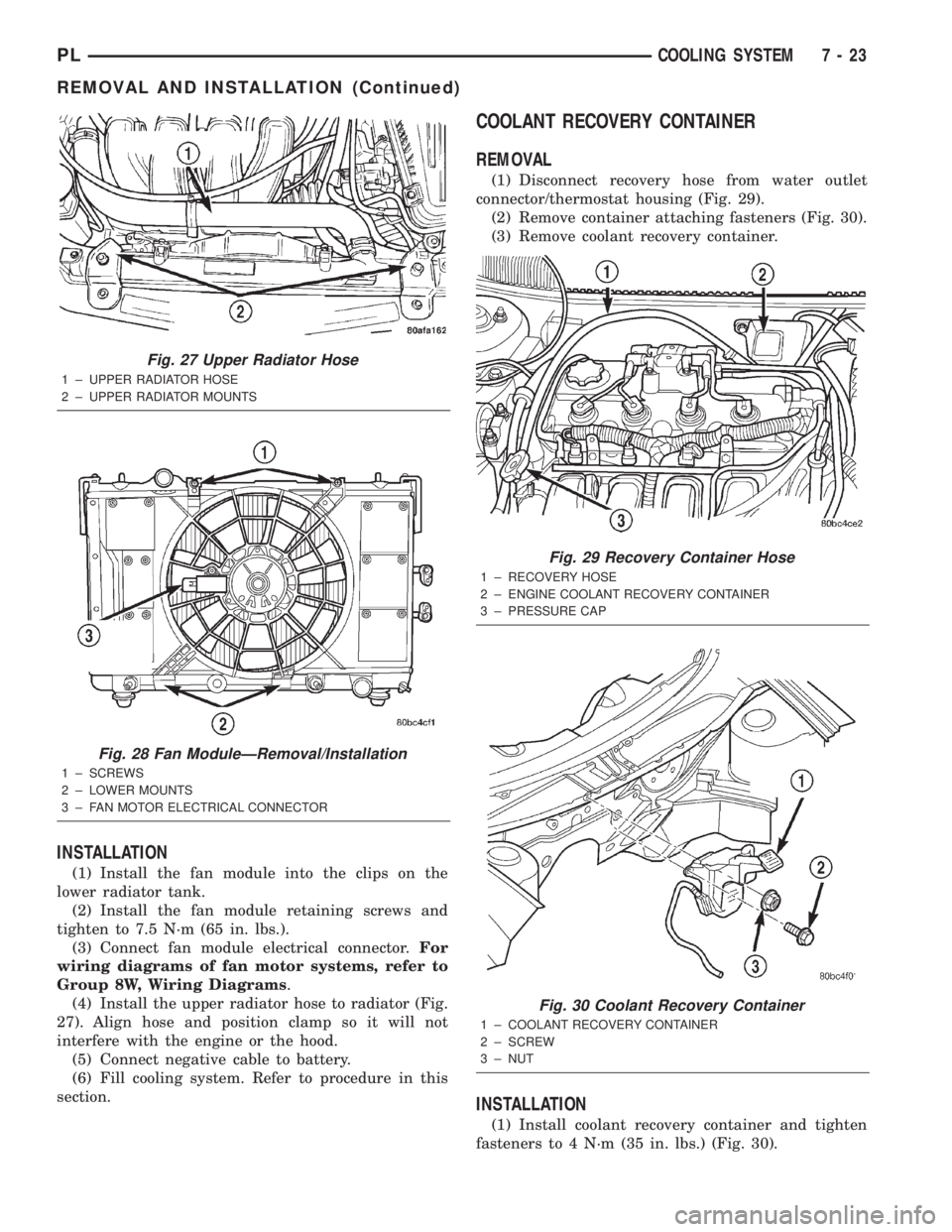
(3) Remove upper radiator hose from radiator (Fig.
27).
(4) Disconnect fan module electrical connector.
(5) Remove fan module screws from radiator (Fig.
28).
(6) Lift fan shroud up and out of lower shroud
attachment clips.
(7) Refer to Disassembly and Assembly in this sec-
tion for fan module sub-component service proce-
dures.
Fig. 25 A/C Condenser to Radiator Mounting Screws
1 ± AIR CONDITIONING CONDENSER TO RADIATOR
MOUNTING SCREWS
2 ± LOWER ISOLATOR MOUNTS
Fig. 26 Draincock
1 ± DRAIN COCK BODY
2 ± DRAIN COCK HOUSING
7 - 22 COOLING SYSTEMPL
REMOVAL AND INSTALLATION (Continued)
Page 202 of 1285
INSTALLATION
(1) Install the fan module into the clips on the
lower radiator tank.
(2) Install the fan module retaining screws and
tighten to 7.5 N´m (65 in. lbs.).
(3) Connect fan module electrical connector.For
wiring diagrams of fan motor systems, refer to
Group 8W, Wiring Diagrams.
(4) Install the upper radiator hose to radiator (Fig.
27). Align hose and position clamp so it will not
interfere with the engine or the hood.
(5) Connect negative cable to battery.
(6) Fill cooling system. Refer to procedure in this
section.
COOLANT RECOVERY CONTAINER
REMOVAL
(1) Disconnect recovery hose from water outlet
connector/thermostat housing (Fig. 29).
(2) Remove container attaching fasteners (Fig. 30).
(3) Remove coolant recovery container.
INSTALLATION
(1) Install coolant recovery container and tighten
fasteners to 4 N´m (35 in. lbs.) (Fig. 30).
Fig. 27 Upper Radiator Hose
1 ± UPPER RADIATOR HOSE
2 ± UPPER RADIATOR MOUNTS
Fig. 28 Fan ModuleÐRemoval/Installation
1 ± SCREWS
2 ± LOWER MOUNTS
3 ± FAN MOTOR ELECTRICAL CONNECTOR
Fig. 29 Recovery Container Hose
1 ± RECOVERY HOSE
2 ± ENGINE COOLANT RECOVERY CONTAINER
3 ± PRESSURE CAP
Fig. 30 Coolant Recovery Container
1 ± COOLANT RECOVERY CONTAINER
2 ± SCREW
3 ± NUT
PLCOOLING SYSTEM 7 - 23
REMOVAL AND INSTALLATION (Continued)
Page 203 of 1285
(2) Connect recovery hose to water outlet connec-
tor/thermostat housing (Fig. 29).
(3) Fill container to proper level. Refer to Cooling
System Refilling in this section.
ENGINE BLOCK HEATER
REMOVAL
(1) Drain coolant from radiator and cylinder block.
Refer to Cooling System Draining in this section for
procedure.
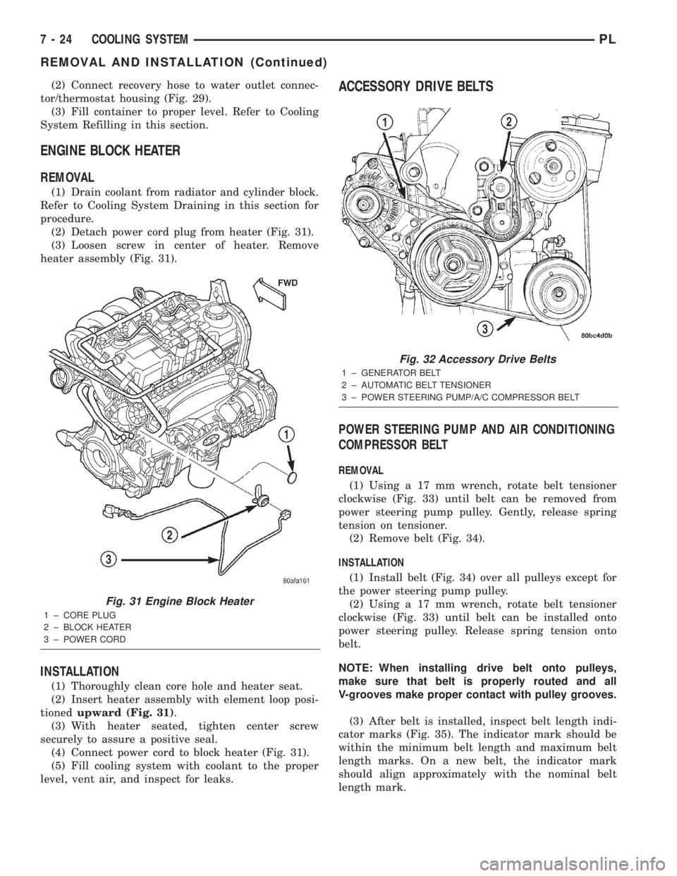
(2) Detach power cord plug from heater (Fig. 31).
(3) Loosen screw in center of heater. Remove
heater assembly (Fig. 31).
INSTALLATION
(1) Thoroughly clean core hole and heater seat.
(2) Insert heater assembly with element loop posi-
tionedupward (Fig. 31).
(3) With heater seated, tighten center screw
securely to assure a positive seal.
(4) Connect power cord to block heater (Fig. 31).
(5) Fill cooling system with coolant to the proper
level, vent air, and inspect for leaks.
ACCESSORY DRIVE BELTS
POWER STEERING PUMP AND AIR CONDITIONING
COMPRESSOR BELT
REMOVAL
(1) Using a 17 mm wrench, rotate belt tensioner
clockwise (Fig. 33) until belt can be removed from
power steering pump pulley. Gently, release spring
tension on tensioner.
(2) Remove belt (Fig. 34).
INSTALLATION
(1) Install belt (Fig. 34) over all pulleys except for
the power steering pump pulley.
(2) Using a 17 mm wrench, rotate belt tensioner
clockwise (Fig. 33) until belt can be installed onto
power steering pulley. Release spring tension onto
belt.
NOTE: When installing drive belt onto pulleys,
make sure that belt is properly routed and all
V-grooves make proper contact with pulley grooves.
(3) After belt is installed, inspect belt length indi-
cator marks (Fig. 35). The indicator mark should be
within the minimum belt length and maximum belt
length marks. On a new belt, the indicator mark
should align approximately with the nominal belt
length mark.
Fig. 31 Engine Block Heater
1 ± CORE PLUG
2 ± BLOCK HEATER
3 ± POWER CORD
Fig. 32 Accessory Drive Belts
1 ± GENERATOR BELT
2 ± AUTOMATIC BELT TENSIONER
3 ± POWER STEERING PUMP/A/C COMPRESSOR BELT
7 - 24 COOLING SYSTEMPL
REMOVAL AND INSTALLATION (Continued)
Page 207 of 1285
SHROUD
REMOVAL
(1) Remove cooling fan module. Refer to procedure
in this section.
(2) Remove fan and fan motor as previously
described.
INSTALLATION
(1) Install fan motor and fan as previously
described.
(2) Install cooling fan module. Refer to procedure
in this section.
CLEANING AND INSPECTION
WATER PUMP
Replace water pump body assembly if it has any of
these defects:
(1) Cracks or damage on the body.
(2) Coolant leaks from the shaft seal, evident by
coolant traces on the pump body.
(3) Loose or rough turning bearing.
(4) Impeller rubs either the pump body or the
engine block.
(5) Impeller loose or damaged.
(6) Sprocket or sprocket flange loose or damaged.
ACCESSORY DRIVE BELT INSPECTION
Belt replacement under any or all of the following
conditions is required, excessive wear, frayed cords or
severe glazing.
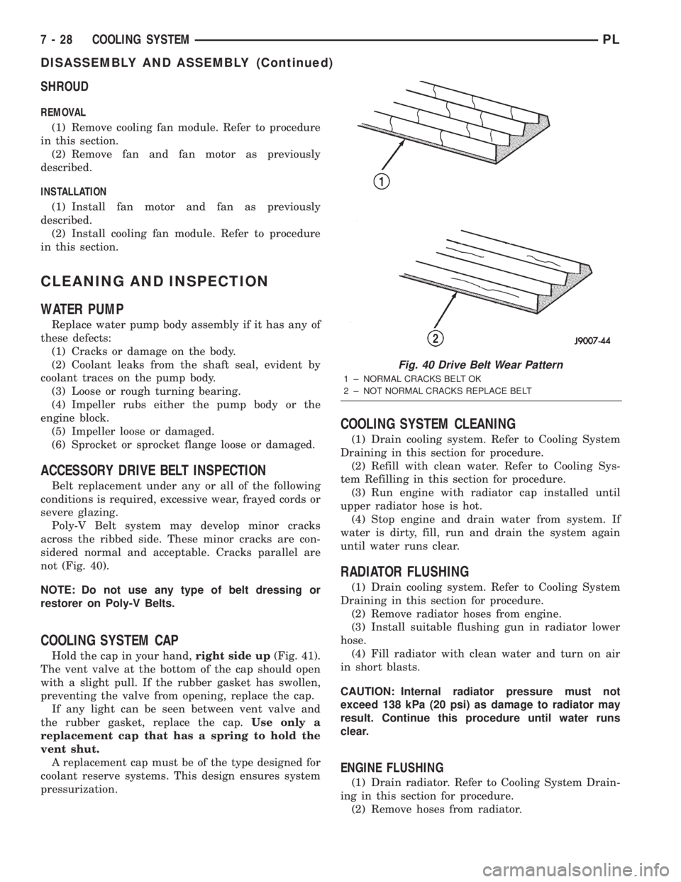
Poly-V Belt system may develop minor cracks
across the ribbed side. These minor cracks are con-
sidered normal and acceptable. Cracks parallel are
not (Fig. 40).
NOTE: Do not use any type of belt dressing or
restorer on Poly-V Belts.
COOLING SYSTEM CAP
Hold the cap in your hand,right side up(Fig. 41).
The vent valve at the bottom of the cap should open
with a slight pull. If the rubber gasket has swollen,
preventing the valve from opening, replace the cap.
If any light can be seen between vent valve and
the rubber gasket, replace the cap.Use only a
replacement cap that has a spring to hold the
vent shut.
A replacement cap must be of the type designed for
coolant reserve systems. This design ensures system
pressurization.
COOLING SYSTEM CLEANING
(1) Drain cooling system. Refer to Cooling System
Draining in this section for procedure.
(2) Refill with clean water. Refer to Cooling Sys-
tem Refilling in this section for procedure.
(3) Run engine with radiator cap installed until
upper radiator hose is hot.
(4) Stop engine and drain water from system. If
water is dirty, fill, run and drain the system again
until water runs clear.
RADIATOR FLUSHING
(1) Drain cooling system. Refer to Cooling System
Draining in this section for procedure.
(2) Remove radiator hoses from engine.
(3) Install suitable flushing gun in radiator lower
hose.
(4) Fill radiator with clean water and turn on air
in short blasts.
CAUTION: Internal radiator pressure must not
exceed 138 kPa (20 psi) as damage to radiator may
result. Continue this procedure until water runs
clear.
ENGINE FLUSHING
(1) Drain radiator. Refer to Cooling System Drain-
ing in this section for procedure.
(2) Remove hoses from radiator.
Fig. 40 Drive Belt Wear Pattern
1 ± NORMAL CRACKS BELT OK
2 ± NOT NORMAL CRACKS REPLACE BELT
7 - 28 COOLING SYSTEMPL
DISASSEMBLY AND ASSEMBLY (Continued)
Page 209 of 1285
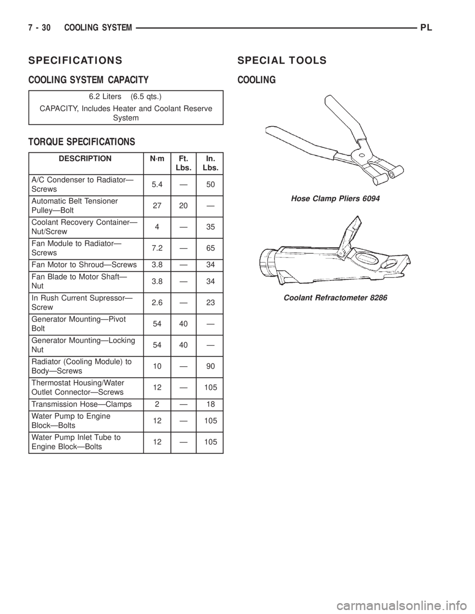
SPECIFICATIONS
COOLING SYSTEM CAPACITY
TORQUE SPECIFICATIONSSPECIAL TOOLS
COOLING
6.2 Liters (6.5 qts.)
CAPACITY, Includes Heater and Coolant Reserve
System
DESCRIPTION N´m Ft.
Lbs.In.
Lbs.
A/C Condenser to RadiatorÐ
Screws5.4 Ð 50
Automatic Belt Tensioner
PulleyÐBolt27 20 Ð
Coolant Recovery ContainerÐ
Nut/Screw4Ð35
Fan Module to RadiatorÐ
Screws7.2 Ð 65
Fan Motor to ShroudÐScrews 3.8 Ð 34
Fan Blade to Motor ShaftÐ
Nut3.8 Ð 34
In Rush Current SupressorÐ
Screw2.6 Ð 23
Generator MountingÐPivot
Bolt54 40 Ð
Generator MountingÐLocking
Nut54 40 Ð
Radiator (Cooling Module) to
BodyÐScrews10 Ð 90
Thermostat Housing/Water
Outlet ConnectorÐScrews12 Ð 105
Transmission HoseÐClamps 2 Ð 18
Water Pump to Engine
BlockÐBolts12 Ð 105
Water Pump Inlet Tube to
Engine BlockÐBolts12 Ð 105
Hose Clamp Pliers 6094
Coolant Refractometer 8286
7 - 30 COOLING SYSTEMPL
Page 246 of 1285
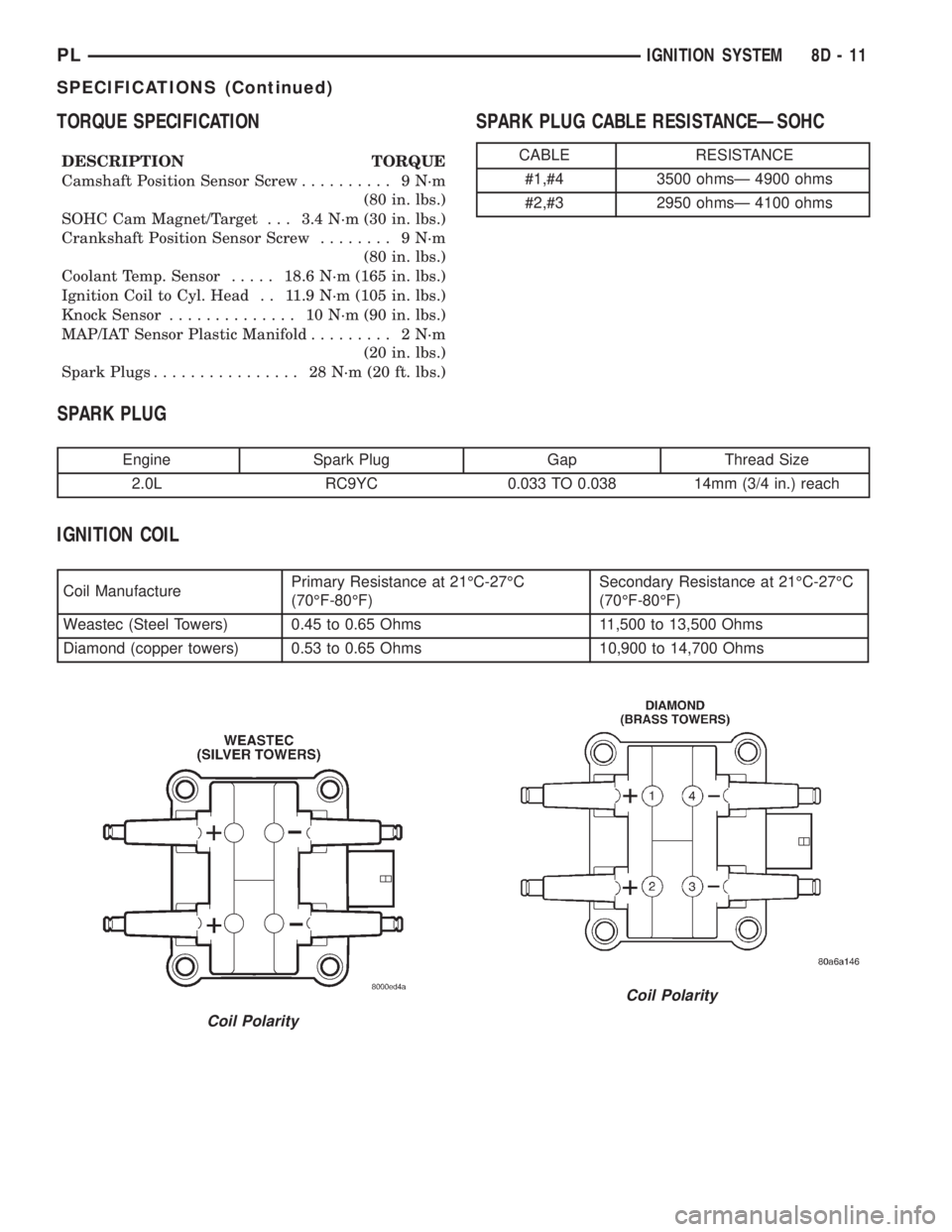
TORQUE SPECIFICATION
DESCRIPTION TORQUE
Camshaft Position Sensor Screw.......... 9N´m
(80 in. lbs.)
SOHC Cam Magnet/Target . . . 3.4 N´m (30 in. lbs.)
Crankshaft Position Sensor Screw........ 9N´m
(80 in. lbs.)
Coolant Temp. Sensor.....18.6 N´m (165 in. lbs.)
Ignition Coil to Cyl. Head . . 11.9 N´m (105 in. lbs.)
Knock Sensor.............. 10N´m(90in.lbs.)
MAP/IAT Sensor Plastic Manifold......... 2N´m
(20 in. lbs.)
Spark Plugs................ 28N´m(20ft.lbs.)
SPARK PLUG CABLE RESISTANCEÐSOHC
SPARK PLUG
Engine Spark Plug Gap Thread Size
2.0L RC9YC 0.033 TO 0.038 14mm (3/4 in.) reach
IGNITION COIL
Coil ManufacturePrimary Resistance at 21ÉC-27ÉC
(70ÉF-80ÉF)Secondary Resistance at 21ÉC-27ÉC
(70ÉF-80ÉF)
Weastec (Steel Towers) 0.45 to 0.65 Ohms 11,500 to 13,500 Ohms
Diamond (copper towers) 0.53 to 0.65 Ohms 10,900 to 14,700 Ohms
CABLE RESISTANCE
#1,#4 3500 ohmsÐ 4900 ohms
#2,#3 2950 ohmsÐ 4100 ohms
Coil Polarity
Coil Polarity
PLIGNITION SYSTEM 8D - 11
SPECIFICATIONS (Continued)
Page 410 of 1285
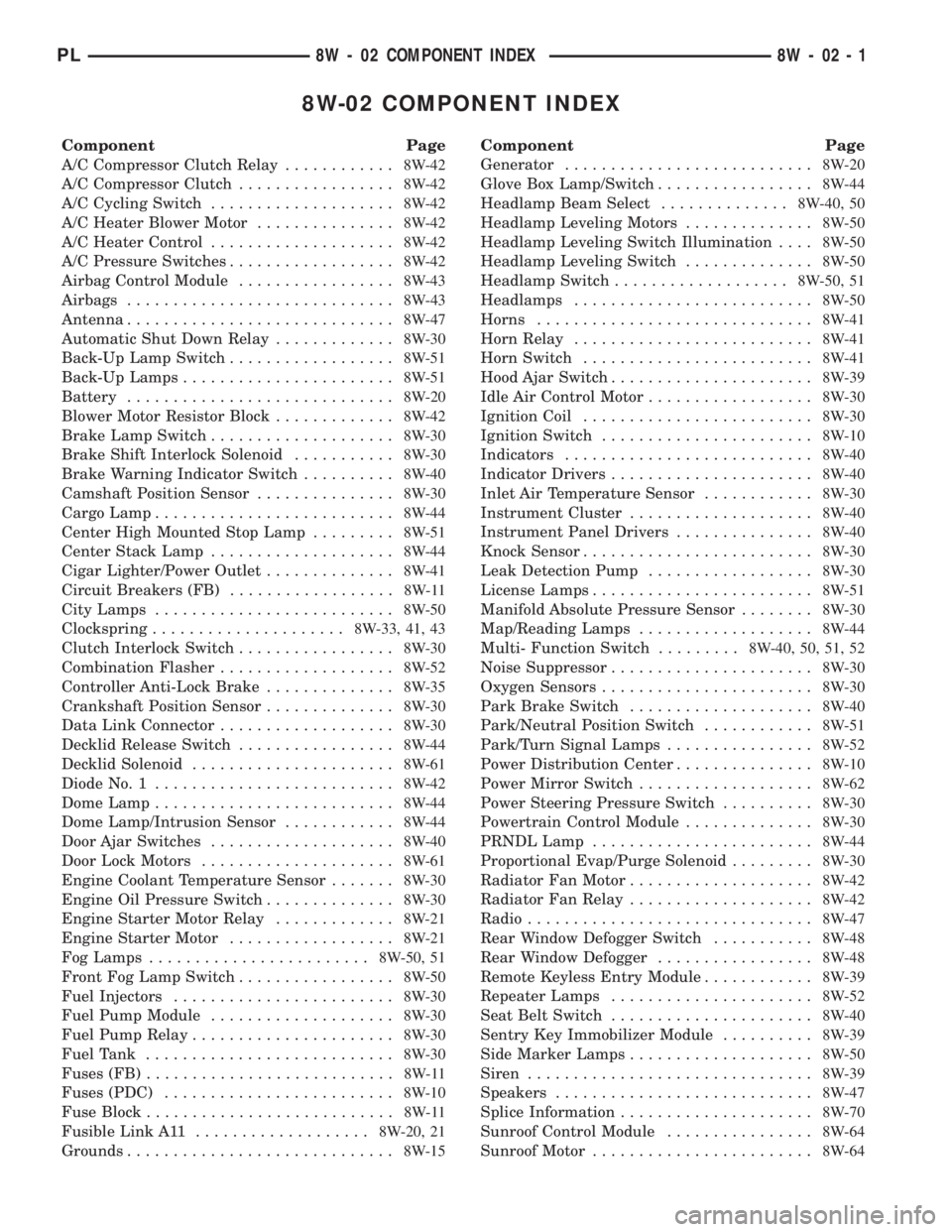
8W-02 COMPONENT INDEX
Component Page
A/C Compressor Clutch Relay............8W-42
A/C Compressor Clutch.................8W-42
A/C Cycling Switch....................8W-42
A/C Heater Blower Motor...............8W-42
A/C Heater Control....................8W-42
A/C Pressure Switches..................8W-42
Airbag Control Module.................8W-43
Airbags.............................8W-43
Antenna.............................8W-47
Automatic Shut Down Relay.............8W-30
Back-Up Lamp Switch..................8W-51
Back-Up Lamps.......................8W-51
Battery.............................8W-20
Blower Motor Resistor Block.............8W-42
Brake Lamp Switch....................8W-30
Brake Shift Interlock Solenoid...........8W-30
Brake Warning Indicator Switch..........8W-40
Camshaft Position Sensor...............8W-30
Cargo Lamp..........................8W-44
Center High Mounted Stop Lamp.........8W-51
Center Stack Lamp....................8W-44
Cigar Lighter/Power Outlet..............8W-41
Circuit Breakers (FB)..................8W-11
City Lamps..........................8W-50
Clockspring.....................8W-33, 41, 43
Clutch Interlock Switch.................8W-30
Combination Flasher...................8W-52
Controller Anti-Lock Brake..............8W-35
Crankshaft Position Sensor..............8W-30
Data Link Connector...................8W-30
Decklid Release Switch.................8W-44
Decklid Solenoid......................8W-61
Diode No. 1..........................8W-42
Dome Lamp..........................8W-44
Dome Lamp/Intrusion Sensor............8W-44
Door Ajar Switches....................8W-40
Door Lock Motors.....................8W-61
Engine Coolant Temperature Sensor.......8W-30
Engine Oil Pressure Switch..............8W-30
Engine Starter Motor Relay.............8W-21
Engine Starter Motor..................8W-21
Fog Lamps........................8W-50, 51
Front Fog Lamp Switch.................8W-50
Fuel Injectors........................8W-30
Fuel Pump Module....................8W-30
Fuel Pump Relay......................8W-30
Fuel Tank...........................8W-30
Fuses (FB)...........................8W-11
Fuses (PDC).........................8W-10
Fuse Block...........................8W-11
Fusible Link A11...................8W-20, 21
Grounds.............................8W-15Component Page
Generator...........................8W-20
Glove Box Lamp/Switch.................8W-44
Headlamp Beam Select..............8W-40, 50
Headlamp Leveling Motors..............8W-50
Headlamp Leveling Switch Illumination....8W-50
Headlamp Leveling Switch..............8W-50
Headlamp Switch...................8W-50, 51
Headlamps..........................8W-50
Horns..............................8W-41
Horn Relay..........................8W-41
Horn Switch.........................8W-41
Hood Ajar Switch......................8W-39
Idle Air Control Motor..................8W-30
Ignition Coil.........................8W-30
Ignition Switch.......................8W-10
Indicators...........................8W-40
Indicator Drivers......................8W-40
Inlet Air Temperature Sensor............8W-30
Instrument Cluster....................8W-40
Instrument Panel Drivers...............8W-40
Knock Sensor.........................8W-30
Leak Detection Pump..................8W-30
License Lamps........................8W-51
Manifold Absolute Pressure Sensor........8W-30
Map/Reading Lamps...................8W-44
Multi- Function Switch.........8W-40, 50, 51, 52
Noise Suppressor......................8W-30
Oxygen Sensors.......................8W-30
Park Brake Switch....................8W-40
Park/Neutral Position Switch............8W-51
Park/Turn Signal Lamps................8W-52
Power Distribution Center...............8W-10
Power Mirror Switch...................8W-62
Power Steering Pressure Switch..........8W-30
Powertrain Control Module..............8W-30
PRNDL Lamp........................8W-44
Proportional Evap/Purge Solenoid.........8W-30
Radiator Fan Motor....................8W-42
Radiator Fan Relay....................8W-42
Radio...............................8W-47
Rear Window Defogger Switch...........8W-48
Rear Window Defogger.................8W-48
Remote Keyless Entry Module............8W-39
Repeater Lamps......................8W-52
Seat Belt Switch......................8W-40
Sentry Key Immobilizer Module..........8W-39
Side Marker Lamps....................8W-50
Siren...............................8W-39
Speakers............................8W-47
Splice Information.....................8W-70
Sunroof Control Module................8W-64
Sunroof Motor........................8W-64
PL8W - 02 COMPONENT INDEX 8W - 02 - 1