2000 DODGE NEON belt
[x] Cancel search: beltPage 234 of 1285
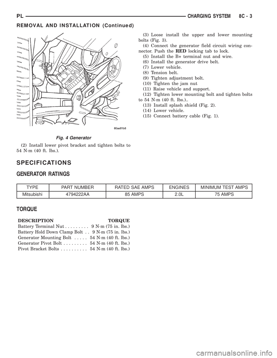
(2) Install lower pivot bracket and tighten bolts to
54 N´m (40 ft. lbs.).(3) Loose install the upper and lower mounting
bolts (Fig. 3).
(4) Connect the generator field circuit wiring con-
nector. Push theREDlocking tab to lock.
(5) Install the B+ terminal nut and wire.
(6) Install the generator drive belt.
(7) Lower vehicle.
(8) Tension belt.
(9) Tighten adjustment bolt.
(10) Tighten the jam nut
(11) Raise vehicle and support.
(12) Tighten lower mounting bolt and tighten bolts
to 54 N´m (40 ft. lbs.)..
(13) Install splash shield (Fig. 2).
(14) Lower vehicle.
(15) Connect battery cable (Fig. 1).
SPECIFICATIONS
GENERATOR RATINGS
TYPE PART NUMBER RATED SAE AMPS ENGINES MINIMUM TEST AMPS
Mitsubishi 4794222AA 85 AMPS 2.0L 75 AMPS
TORQUE
DESCRIPTION TORQUE
Battery Terminal Nut......... 9N´m(75in.lbs.)
Battery Hold Down Clamp Bolt . . 9 N´m (75 in. lbs.)
Generator Mounting Bolt..... 54N´m(40ft.lbs.)
Generator Pivot Bolt......... 54N´m(40ft.lbs.)
Pivot Bracket Bolts.......... 54N´m(40ft.lbs.)
Fig. 4 Generator
PLCHARGING SYSTEM 8C - 3
REMOVAL AND INSTALLATION (Continued)
Page 238 of 1285
OPERATION
The Automatic Shutdown (ASD) relay supplies bat-
tery voltage to the fuel injectors, electronic ignition
coil and the heating elements in the oxygen sensors.
A buss bar in the Power Distribution Center (PDC)
supplies voltage to the solenoid side and contact side
of the relay. The fuse also protects the power circuit
for the fuel pump relay and pump. The fuse is
located in the PDC. Refer to the Wiring Diagrams for
circuit information.
The PCM controls the ASD relay by switching the
ground path for the solenoid side of the relay on and
off. The PCM turns the ground path off when the
ignition switch is in the Off position. When the igni-
tion switch is in On or Start, the PCM monitors the
crankshaft and camshaft position sensor signals to
determine engine speed and ignition timing (coil
dwell). If the PCM does not receive crankshaft and
camshaft position sensor signals when the ignition
switch is in the Run position, it will de-energize the
ASD relay.
CRANKSHAFT POSITION SENSORÐPCM
INPUT
DESCRIPTION
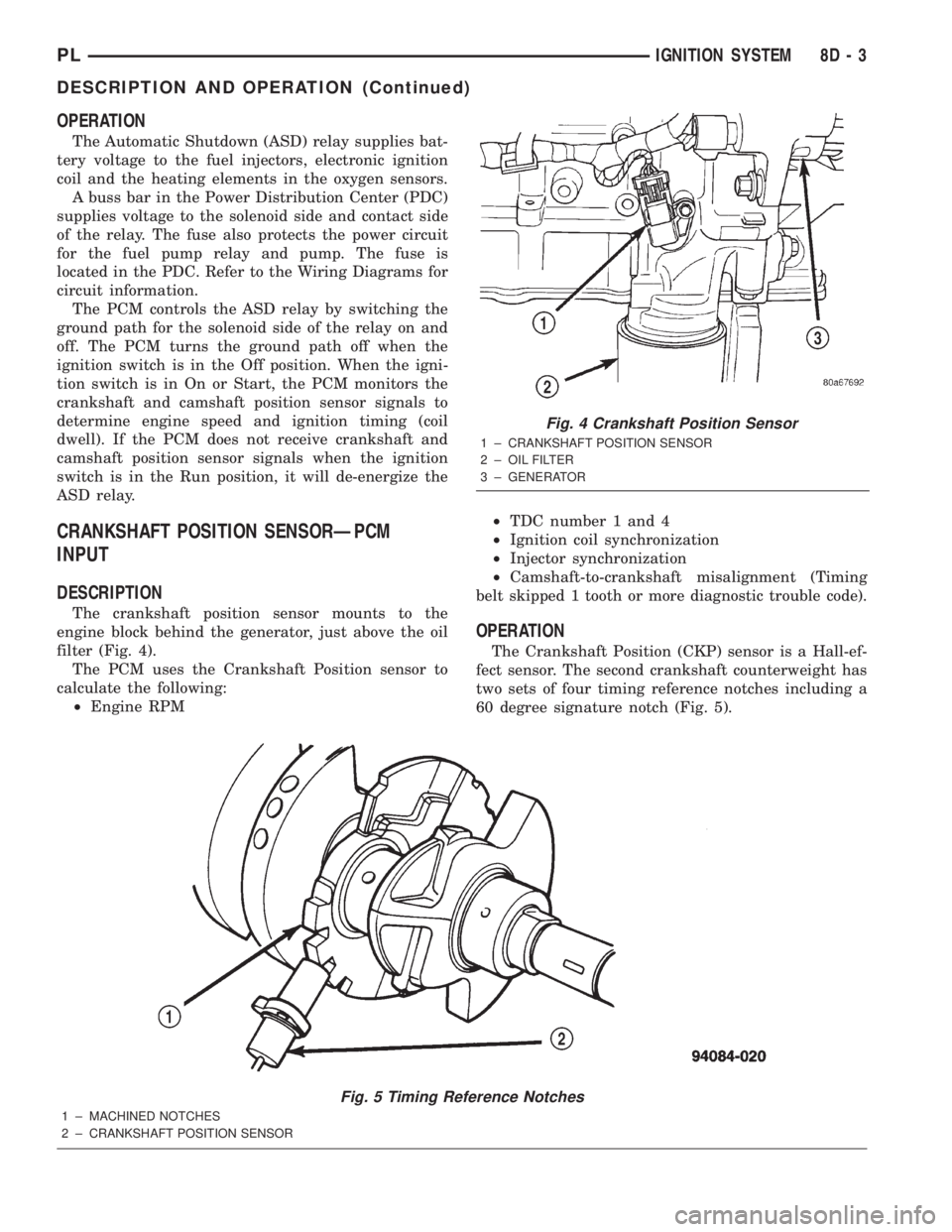
The crankshaft position sensor mounts to the
engine block behind the generator, just above the oil
filter (Fig. 4).
The PCM uses the Crankshaft Position sensor to
calculate the following:
²Engine RPM²TDC number 1 and 4
²Ignition coil synchronization
²Injector synchronization
²Camshaft-to-crankshaft misalignment (Timing
belt skipped 1 tooth or more diagnostic trouble code).
OPERATION
The Crankshaft Position (CKP) sensor is a Hall-ef-
fect sensor. The second crankshaft counterweight has
two sets of four timing reference notches including a
60 degree signature notch (Fig. 5).
Fig. 5 Timing Reference Notches
1 ± MACHINED NOTCHES
2 ± CRANKSHAFT POSITION SENSOR
Fig. 4 Crankshaft Position Sensor
1 ± CRANKSHAFT POSITION SENSOR
2 ± OIL FILTER
3 ± GENERATOR
PLIGNITION SYSTEM 8D - 3
DESCRIPTION AND OPERATION (Continued)
Page 249 of 1285
DESCRIPTION AND OPERATION
HEADLAMP SWITCH
The headlamp switch is part of the Multi-Function
Switch. Refer to Group 8J, Turn Signal and Flasher
for the Multi-Function Switch Test, Removal and
Installation procedures.
INSTRUMENT CLUSTER
There are two conventional instrument cluster
assemblies available. The clusters electronically drive
the speedometer, odometer, gauges, and tachometer
(if equipped). Refer to (Fig. 2) and (Fig. 3).
The instrument cluster controls the courtesy
lamps, it receives and sends messages to other mod-
ules via the PCI bus circuit, it controls all the instru-
ment illumination and the chime is also an integral
part of the cluster. The front turn signals are wired
through the cluster and then go to the front lamps.
The reason being that the DRL module is built into
the cluster (if equipped).
All gauges in the electronic clusters are the analog
type gauges. When the ignition switch is moved to
the OFF position, the cluster drives each gauge to its
lowest position. The individual gauges are not servi-
cable and require complete replacement of the cluster
if one or more gauges are inoperable.
One button is used to switch the display from trip
to total mileage. Holding the button when the display
is in the trip mode will reset the trip mileage. This
button is also used to put the cluster in self-diagnos-
tic mode. Refer to Service Procedures, Cluster Self-
Diagnostics in this section. Most of the indicators will
come on briefly for a bulb heck when the ignition is
turned from OFF to ON. All of the LED's are replace-
able.
In the event that the instrument cluster looses
communication with all other modules on the PCI
bus, the cluster will display ªnobusº in the VF dis-
play. The VF display also displays ªDoorº, ªCruiseº,
ªTracº, and odometer trip or total.
If the cluster does not detect voltage on the cour-
tesy lamp circuit, the message ªFUSEº will alternate
with the odometer/trip odometer for 30 seconds after
the ignition is turned on and for 15 seconds after the
vehicle is first moved. The lack of voltage can be due
to the M1 Fused B(+) (IOD) fuse being open, a bad or
missing courtesy lamp bulb, or a circuit problem.
WARNING AND INDICATOR LAMPS
The instrument cluster has warning lamps and
indicators for the following systems:
²Airbag
²Anti-lock Brakes (ABS) if equipped
²Brake warning
²Charging System²Front fog lamps (if equipped)
²High beam indicator
²Low fuel (premium cluster only)
²Low oil pressure
²Malfunction indicator (service engine soon) lamp
²Right and left turn signals
²Seat belt warning
²Security system
²Trac-Off (ABS equipped vehicles only)
The instrument cluster has a Vacuum Fluorescent
(VF) display for the following systems:
²Cruise
²Door (ajar)
²Odometer
²Set (cruise)
²Trac
²Trip
DIAGNOSIS AND TESTING
AIRBAG WARNING SYSTEM
For testing of this system refer to Group 8M, Pas-
sive Restraint Systems.
BRAKE SYSTEM WARNING LAMP TEST
The brake warning lamp illuminates when the
parking brake is applied with ignition switch turned
to the ON position. The same lamp will also illumi-
nate if one of the two service brake systems fail the
when brake pedal is applied.
To test the system:
²As the ignition switch is turned to the start posi-
tion the lamp should light.
²Turn ignition switch to the ON position and
apply the parking brake. The lamp should light.
If lamp fails to light inspect for:
²A burned out lamp
²Loose, corroded or damaged socket
²A damaged circuit board
²A broken or disconnected wire at the switch
²Defective switch
To test the service brake warning system, refer to
Group 5, Brakes, Hydraulic System Control Valves.
INSTRUMENT CLUSTER LAMPS
Every time the vehicle is switched to the START/
RUN position, the cluster goes through a BULB
CHECK. This tests most of the indicator lamps and
Vacuum Fluorescent (VF) displays. If only one lamp
is out, remove the instrument cluster and replace the
defective bulb or Light Emitting Diode (LED). If
some or all of the lamps fail to light, refer to the
proper Body Diagnostics Procedures Manual.
8E - 2 INSTRUMENT PANEL SYSTEMSPL
Page 250 of 1285
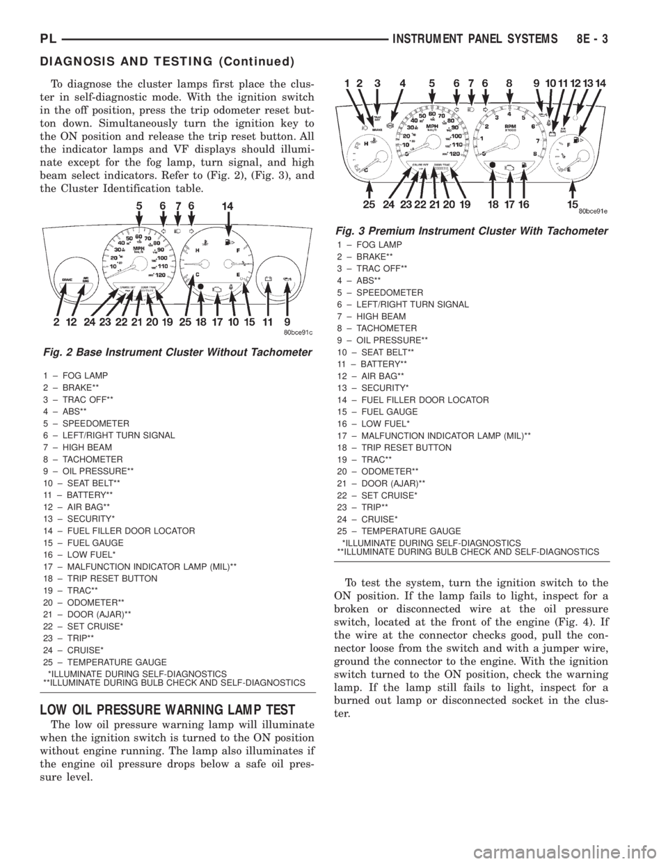
To diagnose the cluster lamps first place the clus-
ter in self-diagnostic mode. With the ignition switch
in the off position, press the trip odometer reset but-
ton down. Simultaneously turn the ignition key to
the ON position and release the trip reset button. All
the indicator lamps and VF displays should illumi-
nate except for the fog lamp, turn signal, and high
beam select indicators. Refer to (Fig. 2), (Fig. 3), and
the Cluster Identification table.
1 ± FOG LAMP
2 ± BRAKE**
3 ± TRAC OFF**
4 ± ABS**
5 ± SPEEDOMETER
6 ± LEFT/RIGHT TURN SIGNAL
7 ± HIGH BEAM
8 ± TACHOMETER
9 ± OIL PRESSURE**
10 ± SEAT BELT**
11 ± BATTERY**
12 ± AIR BAG**
13 ± SECURITY*
14 ± FUEL FILLER DOOR LOCATOR
15 ± FUEL GAUGE
16 ± LOW FUEL*
17 ± MALFUNCTION INDICATOR LAMP (MIL)**
18 ± TRIP RESET BUTTON
19 ± TRAC**
20 ± ODOMETER**
21 ± DOOR (AJAR)**
22 ± SET CRUISE*
23 ± TRIP**
24 ± CRUISE*
25 ± TEMPERATURE GAUGE
*ILLUMINATE DURING SELF-DIAGNOSTICS
**ILLUMINATE DURING BULB CHECK AND SELF-DIAGNOSTICS
LOW OIL PRESSURE WARNING LAMP TEST
The low oil pressure warning lamp will illuminate
when the ignition switch is turned to the ON position
without engine running. The lamp also illuminates if
the engine oil pressure drops below a safe oil pres-
sure level.To test the system, turn the ignition switch to the
ON position. If the lamp fails to light, inspect for a
broken or disconnected wire at the oil pressure
switch, located at the front of the engine (Fig. 4). If
the wire at the connector checks good, pull the con-
nector loose from the switch and with a jumper wire,
ground the connector to the engine. With the ignition
switch turned to the ON position, check the warning
lamp. If the lamp still fails to light, inspect for a
burned out lamp or disconnected socket in the clus-
ter.
Fig. 2 Base Instrument Cluster Without Tachometer
Fig. 3 Premium Instrument Cluster With Tachometer
1 ± FOG LAMP
2 ± BRAKE**
3 ± TRAC OFF**
4 ± ABS**
5 ± SPEEDOMETER
6 ± LEFT/RIGHT TURN SIGNAL
7 ± HIGH BEAM
8 ± TACHOMETER
9 ± OIL PRESSURE**
10 ± SEAT BELT**
11 ± BATTERY**
12 ± AIR BAG**
13 ± SECURITY*
14 ± FUEL FILLER DOOR LOCATOR
15 ± FUEL GAUGE
16 ± LOW FUEL*
17 ± MALFUNCTION INDICATOR LAMP (MIL)**
18 ± TRIP RESET BUTTON
19 ± TRAC**
20 ± ODOMETER**
21 ± DOOR (AJAR)**
22 ± SET CRUISE*
23 ± TRIP**
24 ± CRUISE*
25 ± TEMPERATURE GAUGE
*ILLUMINATE DURING SELF-DIAGNOSTICS
**ILLUMINATE DURING BULB CHECK AND SELF-DIAGNOSTICS
PLINSTRUMENT PANEL SYSTEMS 8E - 3
DIAGNOSIS AND TESTING (Continued)
Page 251 of 1285
MULTIPLE/INDIVIDUAL GAUGES INOPERATIVE
Test speedometer, tachometer and other gauges for
malfunction:
(1) Remove the cluster. Refer to Cluster Removal
and Installation.
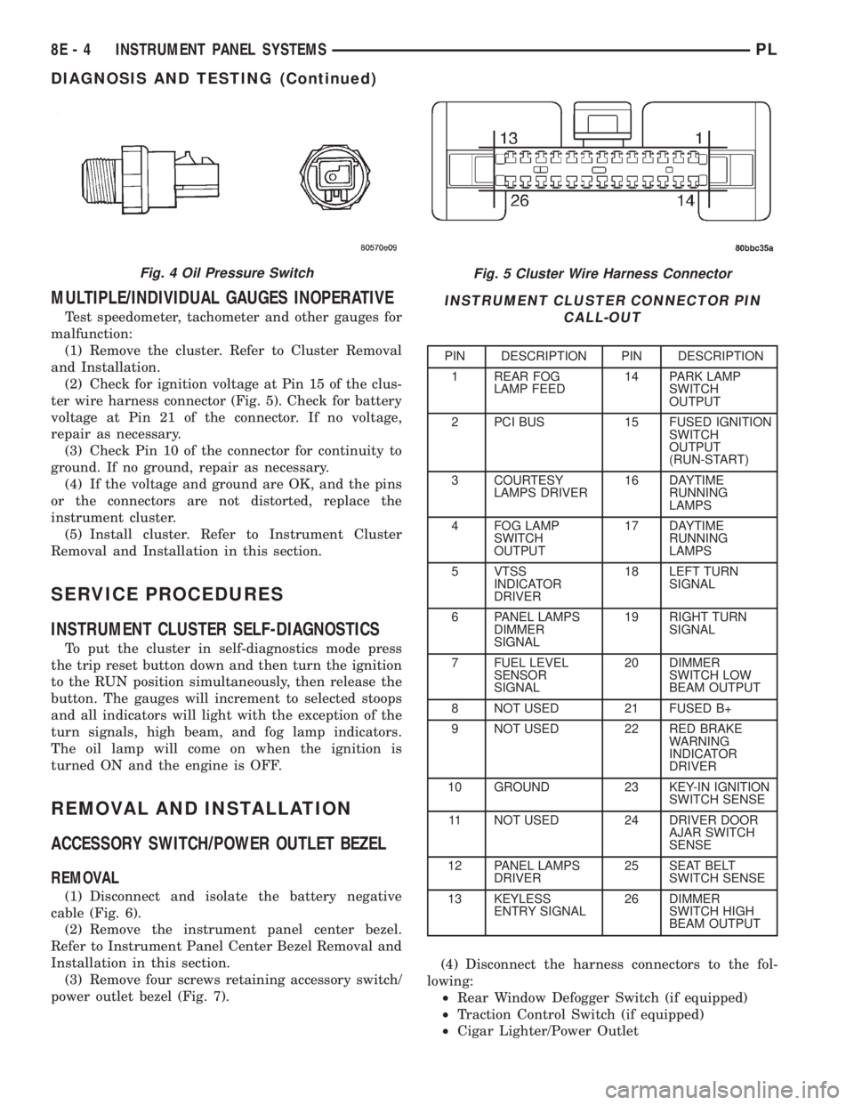
(2) Check for ignition voltage at Pin 15 of the clus-
ter wire harness connector (Fig. 5). Check for battery
voltage at Pin 21 of the connector. If no voltage,
repair as necessary.
(3) Check Pin 10 of the connector for continuity to
ground. If no ground, repair as necessary.
(4) If the voltage and ground are OK, and the pins
or the connectors are not distorted, replace the
instrument cluster.
(5) Install cluster. Refer to Instrument Cluster
Removal and Installation in this section.
SERVICE PROCEDURES
INSTRUMENT CLUSTER SELF-DIAGNOSTICS
To put the cluster in self-diagnostics mode press
the trip reset button down and then turn the ignition
to the RUN position simultaneously, then release the
button. The gauges will increment to selected stoops
and all indicators will light with the exception of the
turn signals, high beam, and fog lamp indicators.
The oil lamp will come on when the ignition is
turned ON and the engine is OFF.
REMOVAL AND INSTALLATION
ACCESSORY SWITCH/POWER OUTLET BEZEL
REMOVAL
(1) Disconnect and isolate the battery negative
cable (Fig. 6).
(2) Remove the instrument panel center bezel.
Refer to Instrument Panel Center Bezel Removal and
Installation in this section.
(3) Remove four screws retaining accessory switch/
power outlet bezel (Fig. 7).(4) Disconnect the harness connectors to the fol-
lowing:
²Rear Window Defogger Switch (if equipped)
²Traction Control Switch (if equipped)
²Cigar Lighter/Power Outlet
Fig. 5 Cluster Wire Harness Connector
INSTRUMENT CLUSTER CONNECTOR PIN
CALL-OUT
PIN DESCRIPTION PIN DESCRIPTION
1 REAR FOG
LAMP FEED14 PARK LAMP
SWITCH
OUTPUT
2 PCI BUS 15 FUSED IGNITION
SWITCH
OUTPUT
(RUN-START)
3 COURTESY
LAMPS DRIVER16 DAYTIME
RUNNING
LAMPS
4 FOG LAMP
SWITCH
OUTPUT17 DAYTIME
RUNNING
LAMPS
5 VTSS
INDICATOR
DRIVER18 LEFT TURN
SIGNAL
6 PANEL LAMPS
DIMMER
SIGNAL19 RIGHT TURN
SIGNAL
7 FUEL LEVEL
SENSOR
SIGNAL20 DIMMER
SWITCH LOW
BEAM OUTPUT
8 NOT USED 21 FUSED B+
9 NOT USED 22 RED BRAKE
WARNING
INDICATOR
DRIVER
10 GROUND 23 KEY-IN IGNITION
SWITCH SENSE
11 NOT USED 24 DRIVER DOOR
AJAR SWITCH
SENSE
12 PANEL LAMPS
DRIVER25 SEAT BELT
SWITCH SENSE
13 KEYLESS
ENTRY SIGNAL26 DIMMER
SWITCH HIGH
BEAM OUTPUT
Fig. 4 Oil Pressure Switch
8E - 4 INSTRUMENT PANEL SYSTEMSPL
DIAGNOSIS AND TESTING (Continued)
Page 309 of 1285
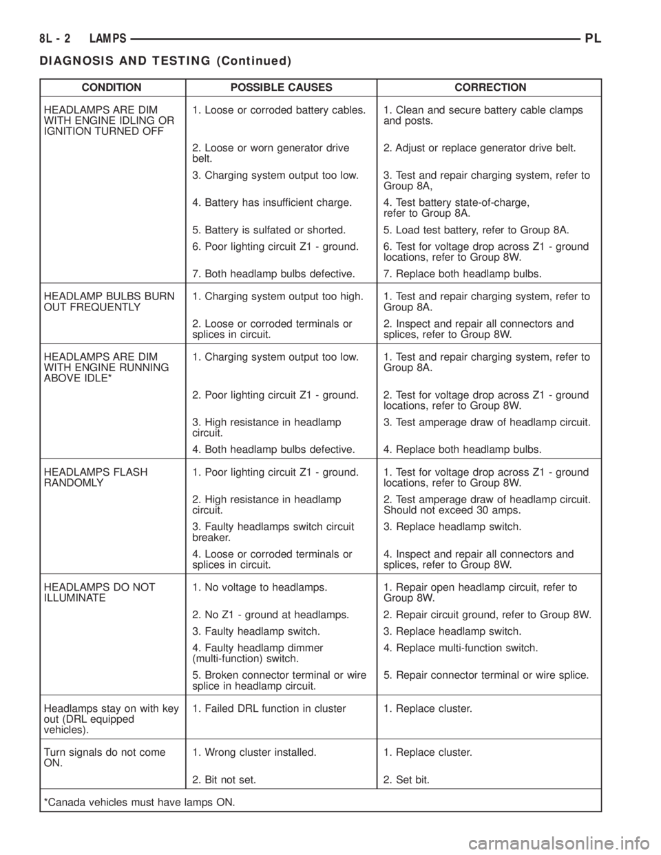
CONDITION POSSIBLE CAUSES CORRECTION
HEADLAMPS ARE DIM
WITH ENGINE IDLING OR
IGNITION TURNED OFF1. Loose or corroded battery cables. 1. Clean and secure battery cable clamps
and posts.
2. Loose or worn generator drive
belt.2. Adjust or replace generator drive belt.
3. Charging system output too low. 3. Test and repair charging system, refer to
Group 8A,
4. Battery has insufficient charge. 4. Test battery state-of-charge,
refer to Group 8A.
5. Battery is sulfated or shorted. 5. Load test battery, refer to Group 8A.
6. Poor lighting circuit Z1 - ground. 6. Test for voltage drop across Z1 - ground
locations, refer to Group 8W.
7. Both headlamp bulbs defective. 7. Replace both headlamp bulbs.
HEADLAMP BULBS BURN
OUT FREQUENTLY1. Charging system output too high. 1. Test and repair charging system, refer to
Group 8A.
2. Loose or corroded terminals or
splices in circuit.2. Inspect and repair all connectors and
splices, refer to Group 8W.
HEADLAMPS ARE DIM
WITH ENGINE RUNNING
ABOVE IDLE*1. Charging system output too low. 1. Test and repair charging system, refer to
Group 8A.
2. Poor lighting circuit Z1 - ground. 2. Test for voltage drop across Z1 - ground
locations, refer to Group 8W.
3. High resistance in headlamp
circuit.3. Test amperage draw of headlamp circuit.
4. Both headlamp bulbs defective. 4. Replace both headlamp bulbs.
HEADLAMPS FLASH
RANDOMLY1. Poor lighting circuit Z1 - ground. 1. Test for voltage drop across Z1 - ground
locations, refer to Group 8W.
2. High resistance in headlamp
circuit.2. Test amperage draw of headlamp circuit.
Should not exceed 30 amps.
3. Faulty headlamps switch circuit
breaker.3. Replace headlamp switch.
4. Loose or corroded terminals or
splices in circuit.4. Inspect and repair all connectors and
splices, refer to Group 8W.
HEADLAMPS DO NOT
ILLUMINATE1. No voltage to headlamps. 1. Repair open headlamp circuit, refer to
Group 8W.
2. No Z1 - ground at headlamps. 2. Repair circuit ground, refer to Group 8W.
3. Faulty headlamp switch. 3. Replace headlamp switch.
4. Faulty headlamp dimmer
(multi-function) switch.4. Replace multi-function switch.
5. Broken connector terminal or wire
splice in headlamp circuit.5. Repair connector terminal or wire splice.
Headlamps stay on with key
out (DRL equipped
vehicles).1. Failed DRL function in cluster 1. Replace cluster.
Turn signals do not come
ON.1. Wrong cluster installed. 1. Replace cluster.
2. Bit not set. 2. Set bit.
*Canada vehicles must have lamps ON.
8L - 2 LAMPSPL
DIAGNOSIS AND TESTING (Continued)
Page 310 of 1285
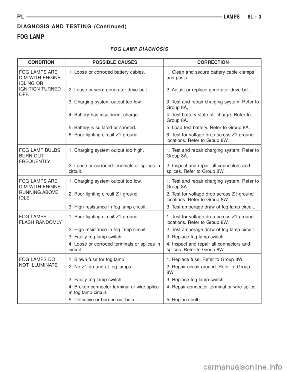
FOG LAMP
FOG LAMP DIAGNOSIS
CONDITION POSSIBLE CAUSES CORRECTION
FOG LAMPS ARE
DIM WITH ENGINE
IDLING OR
IGNITION TURNED
OFF.1. Loose or corroded battery cables. 1. Clean and secure battery cable clamps
and posts.
2. Loose or worn generator drive belt. 2. Adjust or replace generator drive belt.
3. Charging system output too low. 3. Test and repair charging system. Refer to
Group 8A,
4. Battery has insufficient charge. 4. Test battery state-of -charge. Refer to
Group 8A.
5. Battery is sulfated or shorted. 5. Load test battery. Refer to Group 8A.
6. Poor lighting circuit Z1-ground. 6. Test for voltage drop across Z1-ground
locations. Refer to Group 8W.
FOG LAMP BULBS
BURN OUT
FREQUENTLY1. Charging system output too high. 1. Test and repair charging system. Refer to
Group 8A.
2. Loose or corroded terminals or splices in
circuit.2. Inspect and repair all connectors and
splices. Refer to Group 8W.
FOG LAMPS ARE
DIM WITH ENGINE
RUNNING ABOVE
IDLE1. Charging system output too low. 1. Test and repair charging system. Refer to
Group 8A.
2. Poor lighting circuit Z1-ground. 2. Test for voltage drop across Z1-ground
locations. Refer to Group 8W.
3. High resistance in fog lamp circuit. 3. Test amperage draw of fog lamp circuit.
FOG LAMPS
FLASH RANDOMLY1. Poor lighting circuit Z1-ground. 1. Test for voltage drop across Z1-ground
locations. Refer to Group 8W.
2. High resistance in fog lamp circuit. 2. Test amperage draw of fog lamp circuit.
3. Faulty fog lamp switch. 3. Replace fog lamp switch.
4. Loose or corroded terminals or splices in
circuit.4. Inspect and repair all connectors and
splices. Refer to Group 8W.
FOG LAMPS DO
NOT ILLUMINATE1. Blown fuse for fog lamp. 1. Replace fuse. Refer to Group 8W.
2. No Z1-ground at fog lamps. 2. Repair circuit ground. Refer to Group
8W.
3. Faulty fog lamp switch. 3. Replace fog lamp switch.
4. Broken connector terminal or wire splice
in fog lamp circuit.4. Repair connector terminal or wire splice.
5. Defective or burned out bulb. 5. Replace bulb.
PLLAMPS 8L - 3
DIAGNOSIS AND TESTING (Continued)
Page 324 of 1285
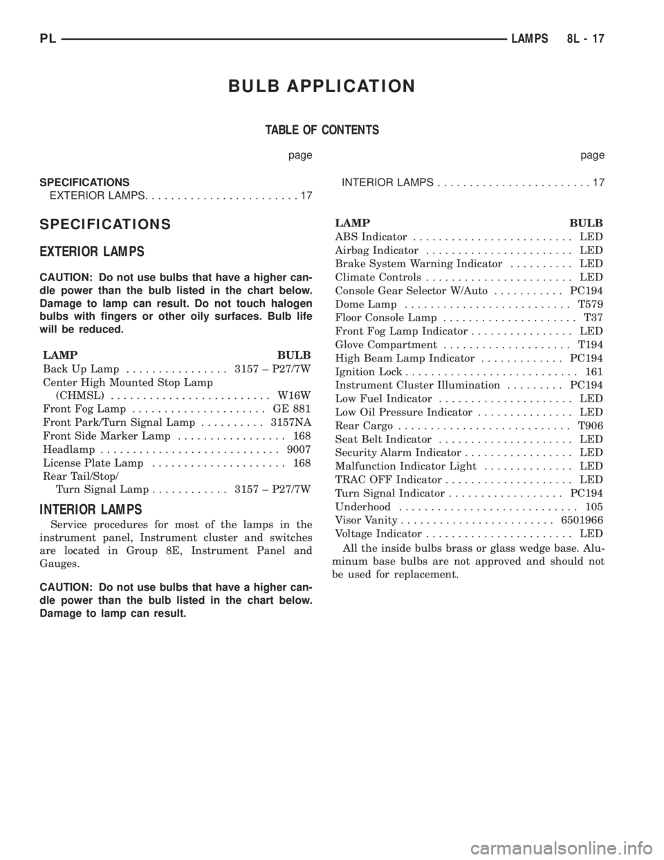
BULB APPLICATION
TABLE OF CONTENTS
page page
SPECIFICATIONS
EXTERIOR LAMPS........................17INTERIOR LAMPS........................17
SPECIFICATIONS
EXTERIOR LAMPS
CAUTION: Do not use bulbs that have a higher can-
dle power than the bulb listed in the chart below.
Damage to lamp can result. Do not touch halogen
bulbs with fingers or other oily surfaces. Bulb life
will be reduced.
LAMP BULB
Back Up Lamp................3157 ± P27/7W
Center High Mounted Stop Lamp
(CHMSL).........................W16W
Front Fog Lamp..................... GE881
Front Park/Turn Signal Lamp..........3157NA
Front Side Marker Lamp................. 168
Headlamp............................9007
License Plate Lamp..................... 168
Rear Tail/Stop/
Turn Signal Lamp............3157 ± P27/7W
INTERIOR LAMPS
Service procedures for most of the lamps in the
instrument panel, Instrument cluster and switches
are located in Group 8E, Instrument Panel and
Gauges.
CAUTION: Do not use bulbs that have a higher can-
dle power than the bulb listed in the chart below.
Damage to lamp can result.LAMP BULB
ABS Indicator......................... LED
Airbag Indicator....................... LED
Brake System Warning Indicator.......... LED
Climate Controls....................... LED
Console Gear Selector W/Auto...........PC194
Dome Lamp..........................T579
Floor Console Lamp..................... T37
Front Fog Lamp Indicator................ LED
Glove Compartment....................T194
High Beam Lamp Indicator.............PC194
Ignition Lock........................... 161
Instrument Cluster Illumination.........PC194
Low Fuel Indicator..................... LED
Low Oil Pressure Indicator............... LED
Rear Cargo...........................T906
Seat Belt Indicator..................... LED
Security Alarm Indicator................. LED
Malfunction Indicator Light.............. LED
TRAC OFF Indicator.................... LED
Turn Signal Indicator..................PC194
Underhood............................ 105
Visor Vanity........................6501966
Voltage Indicator....................... LED
All the inside bulbs brass or glass wedge base. Alu-
minum base bulbs are not approved and should not
be used for replacement.
PLLAMPS 8L - 17