2000 DODGE NEON belt
[x] Cancel search: beltPage 205 of 1285
(3) Install power steering pump and A/C compres-
sor drive belt.
AUTOMATIC BELT TENSIONER & PULLEY
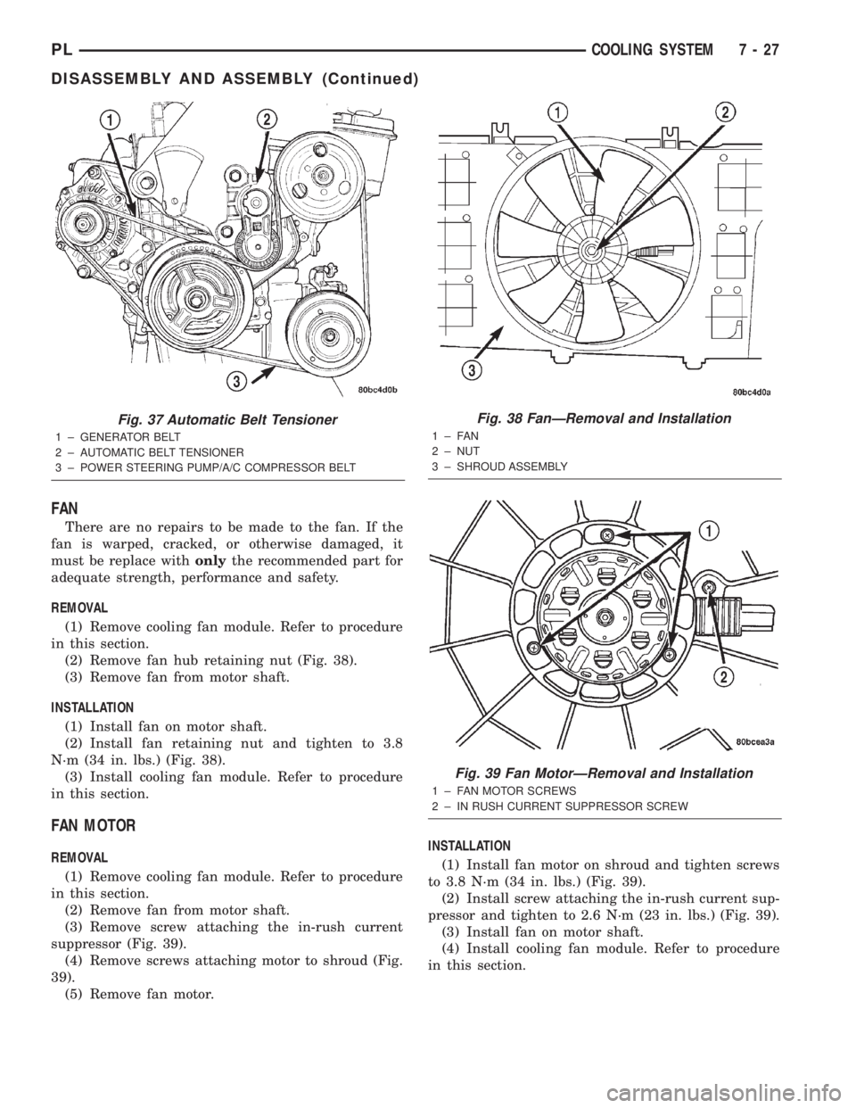
The automatic belt tensioner (Fig. 37) maintains
proper tension on the power steering and air condi-
tioning belt. The tensioner is serviced with the
engine mount bracket assembly. The tensioner pulley
can be serviced.
NOTE: Slight axial movement of the tensioner arm
is normal. Tensioner arm should move freely and
maintain 50±70 lb. tension on belt.
REMOVAL
(1) Remove engine mount bracket assembly. Refer
to Group 9, Engine for procedure.
(2) Remove tensioner pulley mounting bolt.
(3) Remove pulley.
INSTALLATION
(1) Install tensioner pulley and bolt. Tighten bolt
to 27 N´m (20 ft. lbs.).
(2) Install engine mount bracket assembly. Refer
to Group 9, Engine for procedure.
DISASSEMBLY AND ASSEMBLY
COOLING FAN MODULE
The cooling fan module consist of the following
three components: fan, fan motor, and shroud.
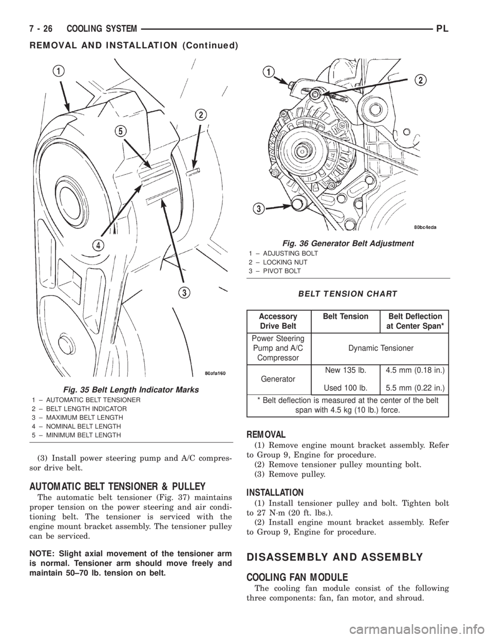
Fig. 35 Belt Length Indicator Marks
1 ± AUTOMATIC BELT TENSIONER
2 ± BELT LENGTH INDICATOR
3 ± MAXIMUM BELT LENGTH
4 ± NOMINAL BELT LENGTH
5 ± MINIMUM BELT LENGTH
Fig. 36 Generator Belt Adjustment
1 ± ADJUSTING BOLT
2 ± LOCKING NUT
3 ± PIVOT BOLT
BELT TENSION CHART
Accessory
Drive BeltBelt Tension Belt Deflection
at Center Span*
Power Steering
Pump and A/C
CompressorDynamic Tensioner
GeneratorNew 135 lb. 4.5 mm (0.18 in.)
Used 100 lb. 5.5 mm (0.22 in.)
* Belt deflection is measured at the center of the belt
span with 4.5 kg (10 lb.) force.
7 - 26 COOLING SYSTEMPL
REMOVAL AND INSTALLATION (Continued)
Page 206 of 1285
FAN
There are no repairs to be made to the fan. If the
fan is warped, cracked, or otherwise damaged, it
must be replace withonlythe recommended part for
adequate strength, performance and safety.
REMOVAL
(1) Remove cooling fan module. Refer to procedure
in this section.
(2) Remove fan hub retaining nut (Fig. 38).
(3) Remove fan from motor shaft.
INSTALLATION
(1) Install fan on motor shaft.
(2) Install fan retaining nut and tighten to 3.8
N´m (34 in. lbs.) (Fig. 38).
(3) Install cooling fan module. Refer to procedure
in this section.
FAN MOTOR
REMOVAL
(1) Remove cooling fan module. Refer to procedure
in this section.
(2) Remove fan from motor shaft.
(3) Remove screw attaching the in-rush current
suppressor (Fig. 39).
(4) Remove screws attaching motor to shroud (Fig.
39).
(5) Remove fan motor.INSTALLATION
(1) Install fan motor on shroud and tighten screws
to 3.8 N´m (34 in. lbs.) (Fig. 39).
(2) Install screw attaching the in-rush current sup-
pressor and tighten to 2.6 N´m (23 in. lbs.) (Fig. 39).
(3) Install fan on motor shaft.
(4) Install cooling fan module. Refer to procedure
in this section.
Fig. 37 Automatic Belt Tensioner
1 ± GENERATOR BELT
2 ± AUTOMATIC BELT TENSIONER
3 ± POWER STEERING PUMP/A/C COMPRESSOR BELT
Fig. 38 FanÐRemoval and Installation
1±FAN
2 ± NUT
3 ± SHROUD ASSEMBLY
Fig. 39 Fan MotorÐRemoval and Installation
1 ± FAN MOTOR SCREWS
2 ± IN RUSH CURRENT SUPPRESSOR SCREW
PLCOOLING SYSTEM 7 - 27
DISASSEMBLY AND ASSEMBLY (Continued)
Page 207 of 1285
SHROUD
REMOVAL
(1) Remove cooling fan module. Refer to procedure
in this section.
(2) Remove fan and fan motor as previously
described.
INSTALLATION
(1) Install fan motor and fan as previously
described.
(2) Install cooling fan module. Refer to procedure
in this section.
CLEANING AND INSPECTION
WATER PUMP
Replace water pump body assembly if it has any of
these defects:
(1) Cracks or damage on the body.
(2) Coolant leaks from the shaft seal, evident by
coolant traces on the pump body.
(3) Loose or rough turning bearing.
(4) Impeller rubs either the pump body or the
engine block.
(5) Impeller loose or damaged.
(6) Sprocket or sprocket flange loose or damaged.
ACCESSORY DRIVE BELT INSPECTION
Belt replacement under any or all of the following
conditions is required, excessive wear, frayed cords or
severe glazing.
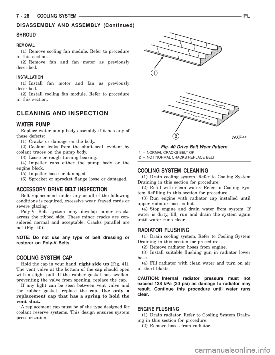
Poly-V Belt system may develop minor cracks
across the ribbed side. These minor cracks are con-
sidered normal and acceptable. Cracks parallel are
not (Fig. 40).
NOTE: Do not use any type of belt dressing or
restorer on Poly-V Belts.
COOLING SYSTEM CAP
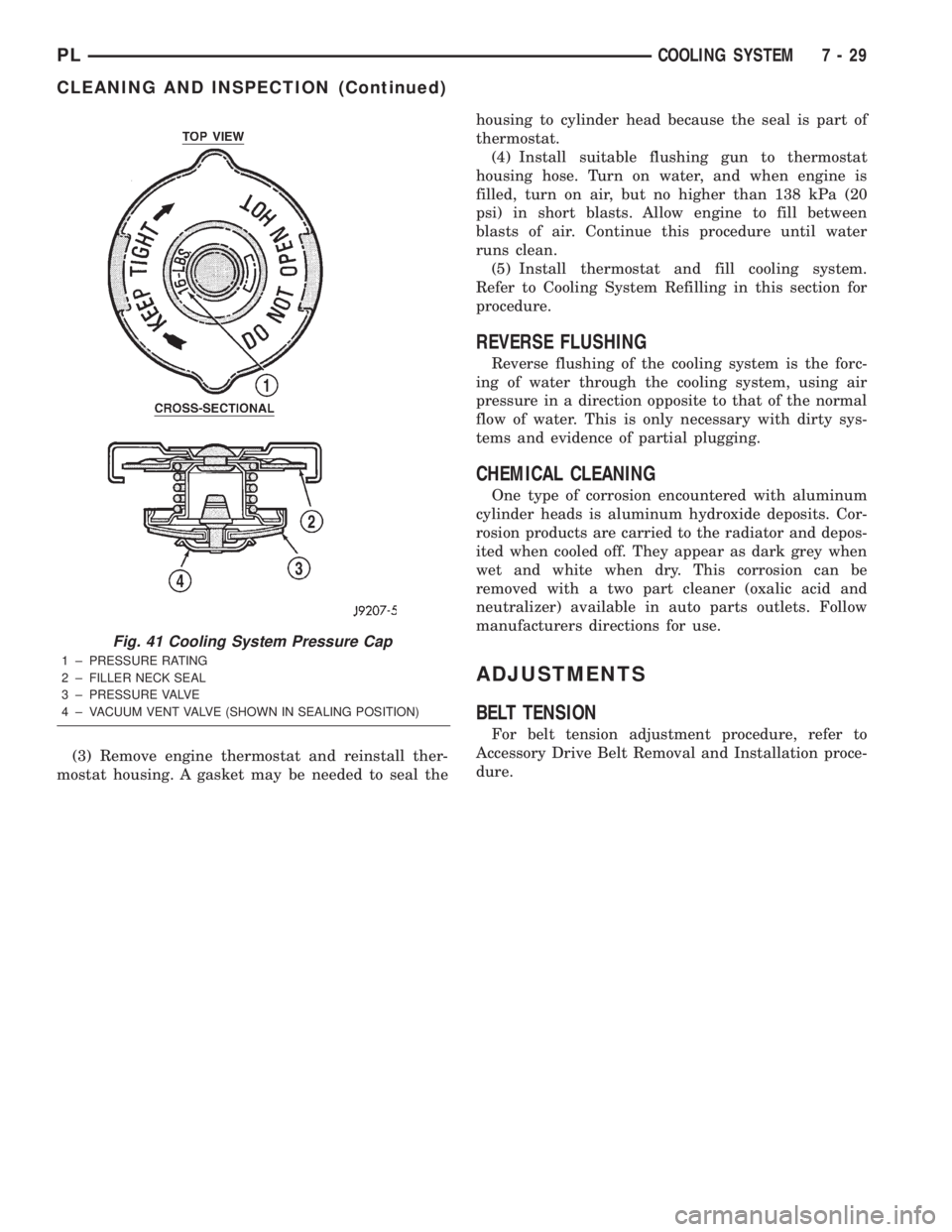
Hold the cap in your hand,right side up(Fig. 41).
The vent valve at the bottom of the cap should open
with a slight pull. If the rubber gasket has swollen,
preventing the valve from opening, replace the cap.
If any light can be seen between vent valve and
the rubber gasket, replace the cap.Use only a
replacement cap that has a spring to hold the
vent shut.
A replacement cap must be of the type designed for
coolant reserve systems. This design ensures system
pressurization.
COOLING SYSTEM CLEANING
(1) Drain cooling system. Refer to Cooling System
Draining in this section for procedure.
(2) Refill with clean water. Refer to Cooling Sys-
tem Refilling in this section for procedure.
(3) Run engine with radiator cap installed until
upper radiator hose is hot.
(4) Stop engine and drain water from system. If
water is dirty, fill, run and drain the system again
until water runs clear.
RADIATOR FLUSHING
(1) Drain cooling system. Refer to Cooling System
Draining in this section for procedure.
(2) Remove radiator hoses from engine.
(3) Install suitable flushing gun in radiator lower
hose.
(4) Fill radiator with clean water and turn on air
in short blasts.
CAUTION: Internal radiator pressure must not
exceed 138 kPa (20 psi) as damage to radiator may
result. Continue this procedure until water runs
clear.
ENGINE FLUSHING
(1) Drain radiator. Refer to Cooling System Drain-
ing in this section for procedure.
(2) Remove hoses from radiator.
Fig. 40 Drive Belt Wear Pattern
1 ± NORMAL CRACKS BELT OK
2 ± NOT NORMAL CRACKS REPLACE BELT
7 - 28 COOLING SYSTEMPL
DISASSEMBLY AND ASSEMBLY (Continued)
Page 208 of 1285
(3) Remove engine thermostat and reinstall ther-
mostat housing. A gasket may be needed to seal thehousing to cylinder head because the seal is part of
thermostat.
(4) Install suitable flushing gun to thermostat
housing hose. Turn on water, and when engine is
filled, turn on air, but no higher than 138 kPa (20
psi) in short blasts. Allow engine to fill between
blasts of air. Continue this procedure until water
runs clean.
(5) Install thermostat and fill cooling system.
Refer to Cooling System Refilling in this section for
procedure.
REVERSE FLUSHING
Reverse flushing of the cooling system is the forc-
ing of water through the cooling system, using air
pressure in a direction opposite to that of the normal
flow of water. This is only necessary with dirty sys-
tems and evidence of partial plugging.
CHEMICAL CLEANING
One type of corrosion encountered with aluminum
cylinder heads is aluminum hydroxide deposits. Cor-
rosion products are carried to the radiator and depos-
ited when cooled off. They appear as dark grey when
wet and white when dry. This corrosion can be
removed with a two part cleaner (oxalic acid and
neutralizer) available in auto parts outlets. Follow
manufacturers directions for use.
ADJUSTMENTS
BELT TENSION
For belt tension adjustment procedure, refer to
Accessory Drive Belt Removal and Installation proce-
dure.
Fig. 41 Cooling System Pressure Cap
1 ± PRESSURE RATING
2 ± FILLER NECK SEAL
3 ± PRESSURE VALVE
4 ± VACUUM VENT VALVE (SHOWN IN SEALING POSITION)
PLCOOLING SYSTEM 7 - 29
CLEANING AND INSPECTION (Continued)
Page 209 of 1285
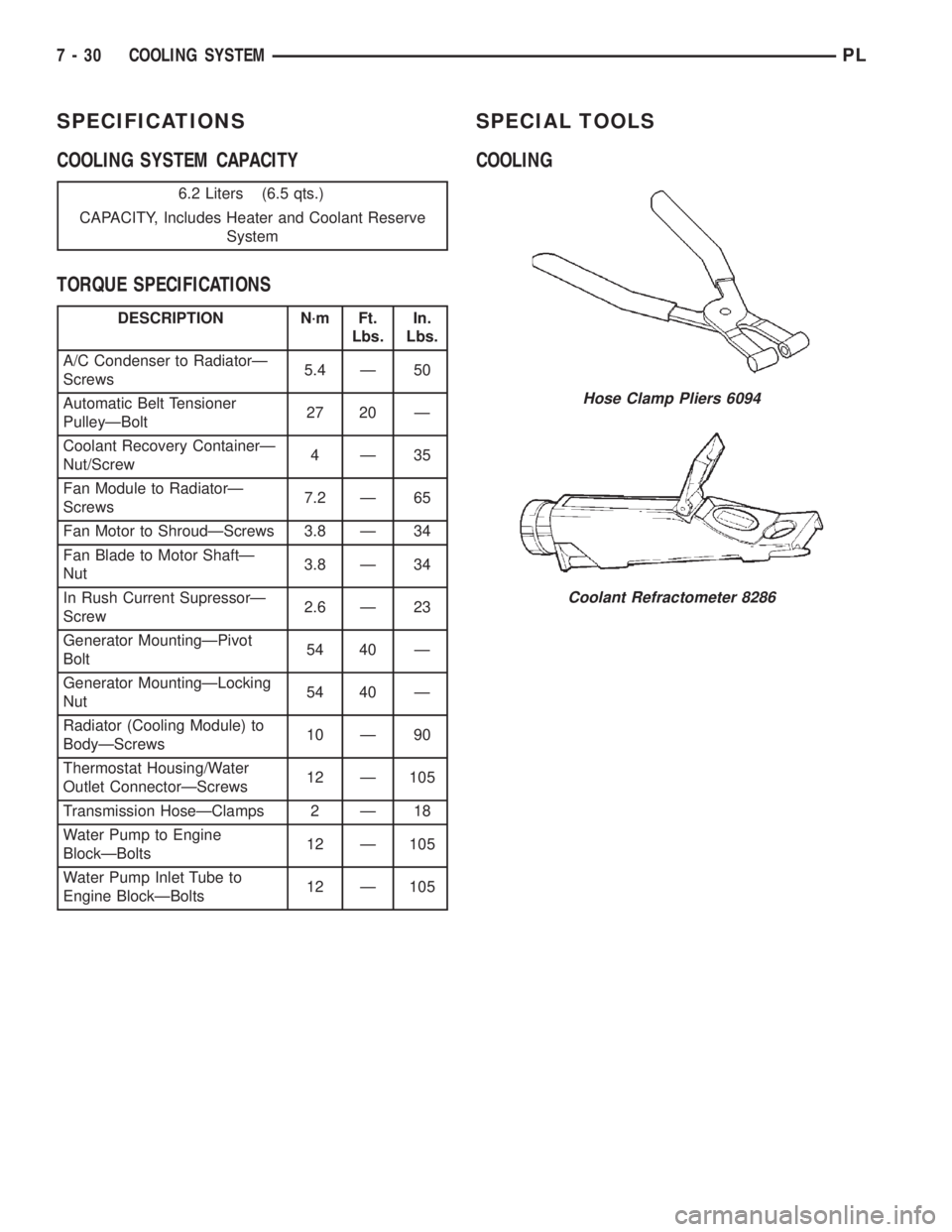
SPECIFICATIONS
COOLING SYSTEM CAPACITY
TORQUE SPECIFICATIONSSPECIAL TOOLS
COOLING
6.2 Liters (6.5 qts.)
CAPACITY, Includes Heater and Coolant Reserve
System
DESCRIPTION N´m Ft.
Lbs.In.
Lbs.
A/C Condenser to RadiatorÐ
Screws5.4 Ð 50
Automatic Belt Tensioner
PulleyÐBolt27 20 Ð
Coolant Recovery ContainerÐ
Nut/Screw4Ð35
Fan Module to RadiatorÐ
Screws7.2 Ð 65
Fan Motor to ShroudÐScrews 3.8 Ð 34
Fan Blade to Motor ShaftÐ
Nut3.8 Ð 34
In Rush Current SupressorÐ
Screw2.6 Ð 23
Generator MountingÐPivot
Bolt54 40 Ð
Generator MountingÐLocking
Nut54 40 Ð
Radiator (Cooling Module) to
BodyÐScrews10 Ð 90
Thermostat Housing/Water
Outlet ConnectorÐScrews12 Ð 105
Transmission HoseÐClamps 2 Ð 18
Water Pump to Engine
BlockÐBolts12 Ð 105
Water Pump Inlet Tube to
Engine BlockÐBolts12 Ð 105
Hose Clamp Pliers 6094
Coolant Refractometer 8286
7 - 30 COOLING SYSTEMPL
Page 213 of 1285
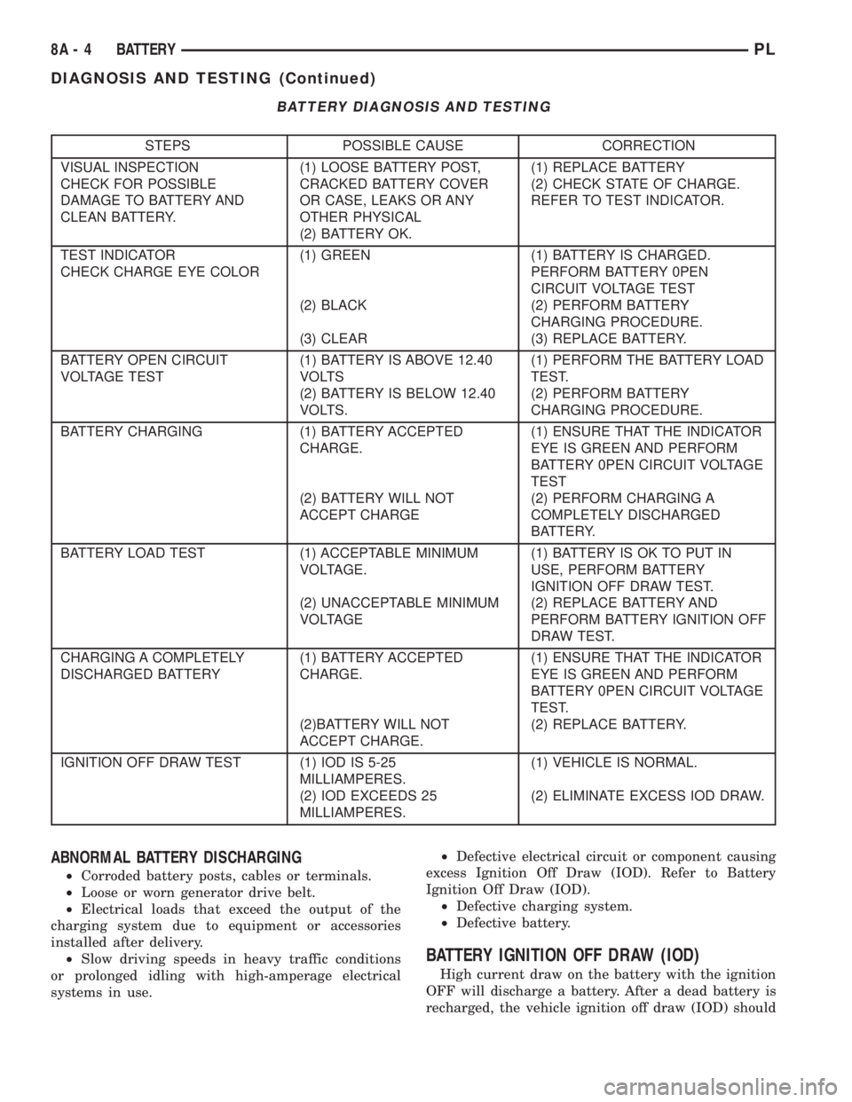
BATTERY DIAGNOSIS AND TESTING
STEPS POSSIBLE CAUSE CORRECTION
VISUAL INSPECTION
CHECK FOR POSSIBLE
DAMAGE TO BATTERY AND
CLEAN BATTERY.(1) LOOSE BATTERY POST,
CRACKED BATTERY COVER
OR CASE, LEAKS OR ANY
OTHER PHYSICAL
(2) BATTERY OK.(1) REPLACE BATTERY
(2) CHECK STATE OF CHARGE.
REFER TO TEST INDICATOR.
TEST INDICATOR
CHECK CHARGE EYE COLOR(1) GREEN
(2) BLACK
(3) CLEAR(1) BATTERY IS CHARGED.
PERFORM BATTERY 0PEN
CIRCUIT VOLTAGE TEST
(2) PERFORM BATTERY
CHARGING PROCEDURE.
(3) REPLACE BATTERY.
BATTERY OPEN CIRCUIT
VOLTAGE TEST(1) BATTERY IS ABOVE 12.40
VOLTS
(2) BATTERY IS BELOW 12.40
VOLTS.(1) PERFORM THE BATTERY LOAD
TEST.
(2) PERFORM BATTERY
CHARGING PROCEDURE.
BATTERY CHARGING (1) BATTERY ACCEPTED
CHARGE.
(2) BATTERY WILL NOT
ACCEPT CHARGE(1) ENSURE THAT THE INDICATOR
EYE IS GREEN AND PERFORM
BATTERY 0PEN CIRCUIT VOLTAGE
TEST
(2) PERFORM CHARGING A
COMPLETELY DISCHARGED
BATTERY.
BATTERY LOAD TEST (1) ACCEPTABLE MINIMUM
VOLTAGE.
(2) UNACCEPTABLE MINIMUM
VOLTAGE(1) BATTERY IS OK TO PUT IN
USE, PERFORM BATTERY
IGNITION OFF DRAW TEST.
(2) REPLACE BATTERY AND
PERFORM BATTERY IGNITION OFF
DRAW TEST.
CHARGING A COMPLETELY
DISCHARGED BATTERY(1) BATTERY ACCEPTED
CHARGE.
(2)BATTERY WILL NOT
ACCEPT CHARGE.(1) ENSURE THAT THE INDICATOR
EYE IS GREEN AND PERFORM
BATTERY 0PEN CIRCUIT VOLTAGE
TEST.
(2) REPLACE BATTERY.
IGNITION OFF DRAW TEST (1) IOD IS 5-25
MILLIAMPERES.
(2) IOD EXCEEDS 25
MILLIAMPERES.(1) VEHICLE IS NORMAL.
(2) ELIMINATE EXCESS IOD DRAW.
ABNORMAL BATTERY DISCHARGING
²Corroded battery posts, cables or terminals.
²Loose or worn generator drive belt.
²Electrical loads that exceed the output of the
charging system due to equipment or accessories
installed after delivery.
²Slow driving speeds in heavy traffic conditions
or prolonged idling with high-amperage electrical
systems in use.²Defective electrical circuit or component causing
excess Ignition Off Draw (IOD). Refer to Battery
Ignition Off Draw (IOD).
²Defective charging system.
²Defective battery.
BATTERY IGNITION OFF DRAW (IOD)
High current draw on the battery with the ignition
OFF will discharge a battery. After a dead battery is
recharged, the vehicle ignition off draw (IOD) should
8A - 4 BATTERYPL
DIAGNOSIS AND TESTING (Continued)
Page 232 of 1285
CHARGING SYSTEM
TABLE OF CONTENTS
page page
DESCRIPTION AND OPERATION
CHARGING SYSTEM.......................1
GENERATOR.............................1
ELECTRONIC VOLTAGE REGULATOR..........1
REMOVAL AND INSTALLATION
GENERATOR.............................2SPECIFICATIONS
GENERATOR RATINGS.....................3
TORQUE................................3
DESCRIPTION AND OPERATION
CHARGING SYSTEM
DESCRIPTION
The charging system consists of:
²Generator
²Electronic Voltage Regulator (EVR) circuitry
within the Powertrain Control Module (PCM)
²Ignition switch (refer to the Ignition System for
information)
²Battery (refer to the Battery for information)
²Battery temperature sensor
²Wiring harness and connections (refer to the
Wiring for information)
OPERATION
The charging system is turned on and off with the
ignition switch. When the ignition switch is turned to
the ON position, battery voltage is applied to the
generator rotor through one of the two field termi-
nals to produce a magnetic field. The generator is
driven by the engine through a serpentine belt and
pulley arrangement.
The amount of DC current produced by the gener-
ator is controlled by the EVR (field control) circuitry,
contained within the PCM. This circuitry is con-
nected in series with the second rotor field terminal
and ground.
Temperature data, along with data from monitored
line voltage, is used by the PCM to vary the battery
charging rate. This is done by cycling the ground
path to control the strength of the rotor magnetic
field. The PCM then compensates and regulates gen-
erator current output accordingly and to maintain
the proper voltage depending on battery tempera-
ture.
All vehicles are equipped with On-Board Diagnos-
tics (OBD). All OBD-sensed systems, including the
EVR (field control) circuitry, are monitored by thePCM. Each monitored circuit is assigned a Diagnos-
tic Trouble Code (DTC). The PCM will store a DTC in
electronic memory for any failure it detects.
GENERATOR
DESCRIPTION
The generator is belt-driven by the engine. It is
serviced only as a complete assembly. If the genera-
tor fails for any reason, the entire assembly must be
replaced.
OPERATION
As the energized rotor begins to rotate within the
generator, the spinning magnetic field induces a cur-
rent into the windings of the stator coil. Once the
generator begins producing sufficient current, it also
provides the current needed to energize the rotor.
The Y type stator winding connections deliver the
induced AC current to 3 positive and 3 negative
diodes for rectification. From the diodes, rectified DC
current is delivered to the vehicles electrical system
through the generator, battery, and ground terminals.
Noise emitting from the generator may be caused
by:
²Worn, loose or defective bearings
²Loose or defective drive pulley
²Incorrect, worn, damaged or misadjusted drive
belt
²Loose mounting bolts
²Misaligned drive pulley
²Defective stator or diode
²Damaged internal fins
ELECTRONIC VOLTAGE REGULATOR
DESCRIPTION
The Electronic Voltage Regulator (EVR) is not a
separate component. It is actually a voltage regulat-
ing circuit located within the Powertrain Control
PLCHARGING SYSTEM 8C - 1
Page 233 of 1285
Module (PCM). The EVR is not serviced separately. If
replacement is necessary, the PCM must be replaced.
OPERATION
The amount of DC current produced by the gener-
ator is controlled by EVR circuitry contained within
the PCM. This circuitry is connected in series with
the generators second rotor field terminal and its
ground.
Voltage is regulated by cycling the ground path to
control the strength of the rotor magnetic field. The
EVR circuitry monitors system line voltage (B+) and
battery temperature (refer to Battery Temperature
Sensor for more information). It then determines a
target charging voltage. If sensed battery voltage is
0.5 volts or lower than the target voltage, the PCM
grounds the field winding until sensed battery volage
is 0.5 volts above target voltage. A circuit in the PCM
cycles the ground side of the generator field up to
100 times per second (100Hz), but has the capability
to ground the field control wire 100% of the time (full
field) to achieve the target voltage. If the charging
rate cannot be monitored (limp-in), a duty cycle of
25% is used by the PCM in order to have some gen-
erator output. Also refer to Charging System Opera-
tion for additional information.
REMOVAL AND INSTALLATION
GENERATOR
REMOVAL
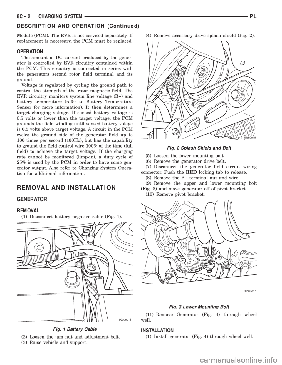
(1) Disconnect battery negative cable (Fig. 1).
(2) Loosen the jam nut and adjustment bolt.
(3) Raise vehicle and support.(4) Remove accessary drive splash shield (Fig. 2).
(5) Loosen the lower mounting bolt.
(6) Remove the generator drive belt.
(7) Disconnect the generator field circuit wiring
connector. Push theREDlocking tab to release.
(8) Remove the B+ terminal nut and wire.
(9) Remove the upper and lower mounting bolt
(Fig. 3) and move generator off of pivot bracket.
(10) Remove pivot bracket.
(11) Remove Generator (Fig. 4) through wheel
well.
INSTALLATION
(1) Install generator (Fig. 4) through wheel well.
Fig. 1 Battery Cable
Fig. 2 Splash Shield and Belt
Fig. 3 Lower Mounting Bolt
8C - 2 CHARGING SYSTEMPL
DESCRIPTION AND OPERATION (Continued)