2000 DODGE NEON oil change
[x] Cancel search: oil changePage 782 of 1285
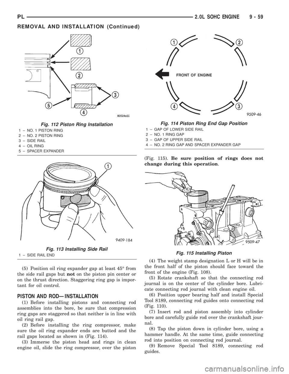
(5) Position oil ring expander gap at least 45É from
the side rail gaps butnoton the piston pin center or
on the thrust direction. Staggering ring gap is impor-
tant for oil control.
PISTON AND RODÐINSTALLATION
(1) Before installing pistons and connecting rod
assemblies into the bore, be sure that compression
ring gaps are staggered so that neither is in line with
oil ring rail gap.
(2) Before installing the ring compressor, make
sure the oil ring expander ends are butted and the
rail gaps located as shown in (Fig. 114).
(3) Immerse the piston head and rings in clean
engine oil, slide the ring compressor, over the piston(Fig. 115).Be sure position of rings does not
change during this operation.
(4) The weight stamp designation L or H will be in
the front half of the piston should face toward the
front of the engine (Fig. 108).
(5) Rotate crankshaft so that the connecting rod
journal is on the center of the cylinder bore. Lubri-
cate connecting rod journal with clean engine oil.
(6) Position upper bearing half and install Special
Tool 8189, connecting rod guides onto connecting rod
(Fig. 110).
(7) Insert rod and piston assembly into cylinder
bore and carefully guide rod over the crankshaft jour-
nal.
(8) Tap the piston down in cylinder bore, using a
hammer handle. At the same time, guide connecting
rod into position on connecting rod journal.
(9) Remove Special Tool 8189, connecting rod
guides.
Fig. 112 Piston Ring Installation
1 ± NO. 1 PISTON RING
2 ± NO. 2 PISTON RING
3 ± SIDE RAIL
4 ± OIL RING
5 ± SPACER EXPANDER
Fig. 113 Installing Side Rail
1 ± SIDE RAIL END
Fig. 114 Piston Ring End Gap Position
1 ± GAP OF LOWER SIDE RAIL
2 ± NO. 1 RING GAP
3 ± GAP OF UPPER SIDE RAIL
4 ± NO. 2 RING GAP AND SPACER EXPANDER GAP
Fig. 115 Installing Piston
PL2.0L SOHC ENGINE 9 - 59
REMOVAL AND INSTALLATION (Continued)
Page 846 of 1285
²Air Conditioning Controls
²Battery Voltage
²Inlet Air/Battery Temperature Sensor
²Brake Switch
²Camshaft Position Sensor
²Crankshaft Position Sensor
²Engine Coolant Temperature Sensor
²Fuel Level Sensor
²Ignition Switch
²Inlet Air/Intake Air Temperature Sensor
²Knock Sensor
²Manifold Absolute Pressure (MAP) Sensor
²Oxygen Sensors
²Power Steering Pressure Switch²SCI Receive
²Speed Control Switches
²Throttle Position Sensor
²Transmission Park/Neutral Switch (automatic
transmission)
²Vehicle Speed Sensor
PCM Outputs:
²Air Conditioning WOT Relay
²Auto Shutdown (ASD) Relay
²Charging Indicator Lamp
²Data Link Connector
²Proportional Purge Solenoid
²EGR Solenoid
²Fuel Injectors
²Fuel Pump Relay
²Generator Field
²Idle Air Control Motor
²Ignition Coils
²Malfunction Indicator (Check Engine) Lamp
²Radiator Fan Relay
²Speed Control Solenoids
²Tachometer
²Torque Convertor Clutch Solenoid
Based on inputs it receives, the PCM adjusts fuel
injector pulse width, idle speed, ignition spark
advance, ignition coil dwell and EVAP canister purge
operation. The PCM regulates the cooling fan, air
conditioning and speed control systems. The PCM
changes generator charge rate by adjusting the gen-
erator field. The PCM also performs diagnostics.
The PCM adjusts injector pulse width (air-fuel
ratio) based on the following inputs.
²Battery voltage
²Coolant temperature
²Inlet Air/Intake air temperature
²Exhaust gas content (oxygen sensor)
²Engine speed (crankshaft position sensor)
²Manifold absolute pressure
²Throttle position
The PCM adjusts ignition timing based on the fol-
lowing inputs.
²Coolant temperature
²Inlet Air/Intake air temperature
²Engine speed (crankshaft position sensor)
²Knock sensor
²Manifold absolute pressure
²Throttle position
²Transmission gear selection (park/neutral
switch)
The PCM also adjusts engine idle speed through
the idle air control motor based on the following
inputs.
²Air conditioning sense
²Battery voltage
²Battery temperature
²Brake switch
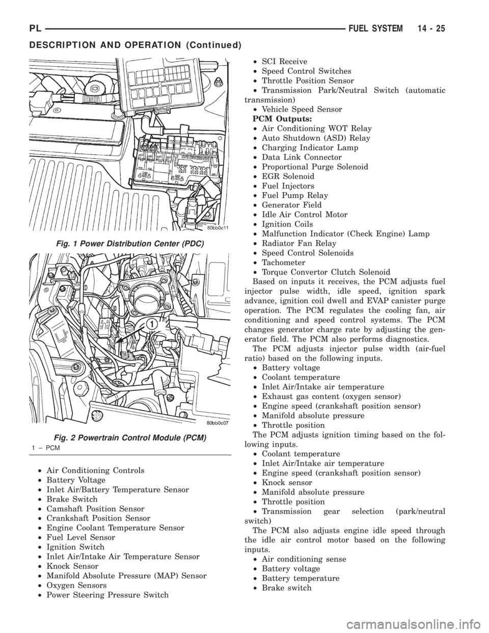
Fig. 1 Power Distribution Center (PDC)
Fig. 2 Powertrain Control Module (PCM)
1 ± PCM
PLFUEL SYSTEM 14 - 25
DESCRIPTION AND OPERATION (Continued)
Page 847 of 1285
²Coolant temperature
²Engine speed (crankshaft position sensor)
²Engine run time
²Manifold absolute pressure
²Power steering pressure switch
²Throttle position
²Transmission gear selection (park/neutral
switch)
²Vehicle distance (speed)
The Auto Shutdown (ASD) and fuel pump relays
are mounted externally, but turned on and off by the
PCM.
The crankshaft position sensor signal is sent to the
PCM. If the PCM does not receive the signal within
approximately one second of engine cranking, it deac-
tivates the ASD relay and fuel pump relay. When
these relays deactivate, power is shut off from the
fuel injectors, ignition coils, heating element in the
oxygen sensors and the fuel pump.
The PCM contains a voltage converter that
changes battery voltage to a regulated 8 volts direct
current to power the camshaft position sensor, crank-
shaft position sensor and vehicle speed sensor. The
PCM also provides a 5 volt direct current supply for
the manifold absolute pressure sensor and throttle
position sensor.
PCM GROUND
OPERATION
Ground is provided through multiple pins of the
PCM connector. Depending on the vehicle there may
be as many as three different ground pins. There are
power grounds and sensor grounds.
The power grounds are used to control the ground
side of any relay, solenoid, ignition coil or injector.
The signal ground is used for any input that uses
sensor return for ground, and the ground side of any
internal processing component.
The SBEC III case is shielded to prevent RFI and
EMI. The PCM case is grounded and must be firmly
attached to a good, clean body ground.
Internally all grounds are connected together, how-
ever there is noise suppression on the sensor ground.
For EMI and RFI protection the case is also
grounded separately from the ground pins.
5 VOLT SUPPLYÐPCM OUTPUT
OPERATION
The PCM supplies 5 volts to the following sensors:
²A/C pressure transducer
²Engine coolant temperature sensor
²Manifold absolute pressure sensor
²Throttle position sensor
²Linear EGR solenoid
8-VOLT SUPPLYÐPCM OUTPUT
OPERATION
The PCM supplies 8 volts to the crankshaft posi-
tion sensor, camshaft position sensor.
FUEL CORRECTION or ADAPTIVE MEMORIES
DESCRIPTION
In Open Loop, the PCM changes pulse width with-
out feedback from the O2 Sensors. Once the engine
warms up to approximately 30 to 35É F, the PCM
goes into closed loopShort Term Correctionand
utilitzes feedback from the O2 Sensors. Closed loop
Long Term Adaptive Memoryis maintained above
170É to 190É F unless the PCM senses wide open
throttle. At that time the PCM returns to Open Loop
operation.
OPERATION
Short Term
The first fuel correction program that begins func-
tioning is the short term fuel correction. This system
corrects fuel delivery in direct proportion to the read-
ings from the Upstream O2 Sensor.
The PCM monitors the air/fuel ratio by using the
input voltage from the O2 Sensor. When the voltage
reaches its preset high or low limit, the PCM begins
to add or remove fuel until the sensor reaches its
switch point. The short term corrections then begin.
The PCM makes a series of quick changes in the
injector pulse-width until the O2 Sensor reaches its
opposite preset limit or switch point. The process
then repeats itself in the opposite direction.
Short term fuel correction will keep increasing or
decreasing injector pulse-width based upon the
upstream O2 Sensor input. The maximum range of
authority for short term memory is 25% (+/-) of base
pulse-width.
Long Term
The second fuel correction program is the long
term adaptive memory. In order to maintain correct
emission throughout all operating ranges of the
engine, a cell structure based on engine rpm and load
(MAP) is used.
There are up to 16 cells. Two cells are used only
during idle, based upon TPS and Park/Neutral
switch inputs. There may be two other cells used for
deceleration, based on TPS, engine rpm, and vehicle
speed. The other twelve cells represent a manifold
pressure and an rpm range. Six of the cells are high
rpm and the other six are low rpm. Each of these
cells is a specific MAP voltage range.
14 - 26 FUEL SYSTEMPL
DESCRIPTION AND OPERATION (Continued)
Page 848 of 1285
As the engine enters one of these cells the PCM
looks at the amount of short term correction being
used. Because the goal is to keep short term at 0 (O2
Sensor switching at 0.5 volt), long term will update
in the same direction as short term correction was
moving to bring the short term back to 0. Once short
term is back at 0, this long term correction factor is
stored in memory.
The values stored in long term adaptive memory
are used for all operating conditions, including open
loop. However, the updating of the long term memoryoccurs after the engine has exceeded approximately
17É F, with fuel control in closed loop and two min-
utes of engine run time. This is done to prevent any
transitional temperature or start-up compensations
from corrupting long term fuel correction.
Long term adaptive memory can change the pulse-
width by as much as 25%, which means it can correct
for all of short term. It is possible to have a problem
that would drive long term to 25% and short term to
another 25% for a total change of 50% away from
base pulse-width calculation.
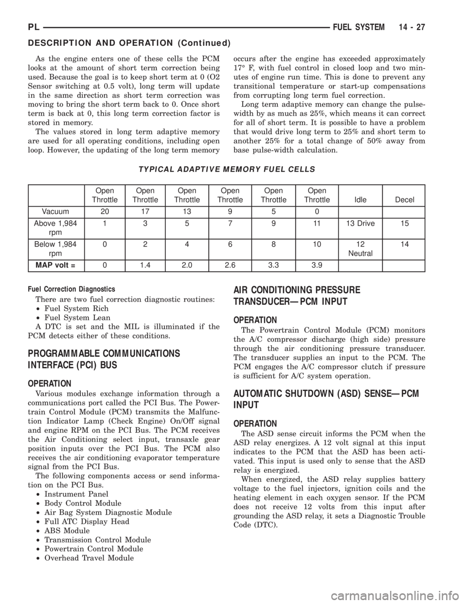
TYPICAL ADAPTIVE MEMORY FUEL CELLS
Open
ThrottleOpen
ThrottleOpen
ThrottleOpen
ThrottleOpen
ThrottleOpen
Throttle Idle Decel
Vacuum 20 17 13 9 5 0
Above 1,984
rpm1 3 5 7 9 11 13 Drive 15
Below 1,984
rpm02 4 6 8 1012
Neutral14
MAP volt =0 1.4 2.0 2.6 3.3 3.9
Fuel Correction Diagnostics
There are two fuel correction diagnostic routines:
²Fuel System Rich
²Fuel System Lean
A DTC is set and the MIL is illuminated if the
PCM detects either of these conditions.
PROGRAMMABLE COMMUNICATIONS
INTERFACE (PCI) BUS
OPERATION
Various modules exchange information through a
communications port called the PCI Bus. The Power-
train Control Module (PCM) transmits the Malfunc-
tion Indicator Lamp (Check Engine) On/Off signal
and engine RPM on the PCI Bus. The PCM receives
the Air Conditioning select input, transaxle gear
position inputs over the PCI Bus. The PCM also
receives the air conditioning evaporator temperature
signal from the PCI Bus.
The following components access or send informa-
tion on the PCI Bus.
²Instrument Panel
²Body Control Module
²Air Bag System Diagnostic Module
²Full ATC Display Head
²ABS Module
²Transmission Control Module
²Powertrain Control Module
²Overhead Travel Module
AIR CONDITIONING PRESSURE
TRANSDUCERÐPCM INPUT
OPERATION
The Powertrain Control Module (PCM) monitors
the A/C compressor discharge (high side) pressure
through the air conditioning pressure transducer.
The transducer supplies an input to the PCM. The
PCM engages the A/C compressor clutch if pressure
is sufficient for A/C system operation.
AUTOMATIC SHUTDOWN (ASD) SENSEÐPCM
INPUT
OPERATION
The ASD sense circuit informs the PCM when the
ASD relay energizes. A 12 volt signal at this input
indicates to the PCM that the ASD has been acti-
vated. This input is used only to sense that the ASD
relay is energized.
When energized, the ASD relay supplies battery
voltage to the fuel injectors, ignition coils and the
heating element in each oxygen sensor. If the PCM
does not receive 12 volts from this input after
grounding the ASD relay, it sets a Diagnostic Trouble
Code (DTC).
PLFUEL SYSTEM 14 - 27
DESCRIPTION AND OPERATION (Continued)
Page 851 of 1285
signal to the PCM, allowing engine starter operation.
The interlock switch is not adjustable.
Clutch Pedal Upstop Switch
With the clutch pedal at rest, the clutch pedal
upstop switch is closed, allowing speed control oper-
ation. When the clutch pedal is depressed, the upstop
switch opens and signals the PCM to cancel speed
control operation, and enter a modified engine cali-
bration schedule to improve driveability during gear-
to-gear shifts. The upstop switch is not adjustable.
CRANKSHAFT POSITION SENSORÐPCM
INPUT
DESCRIPTION
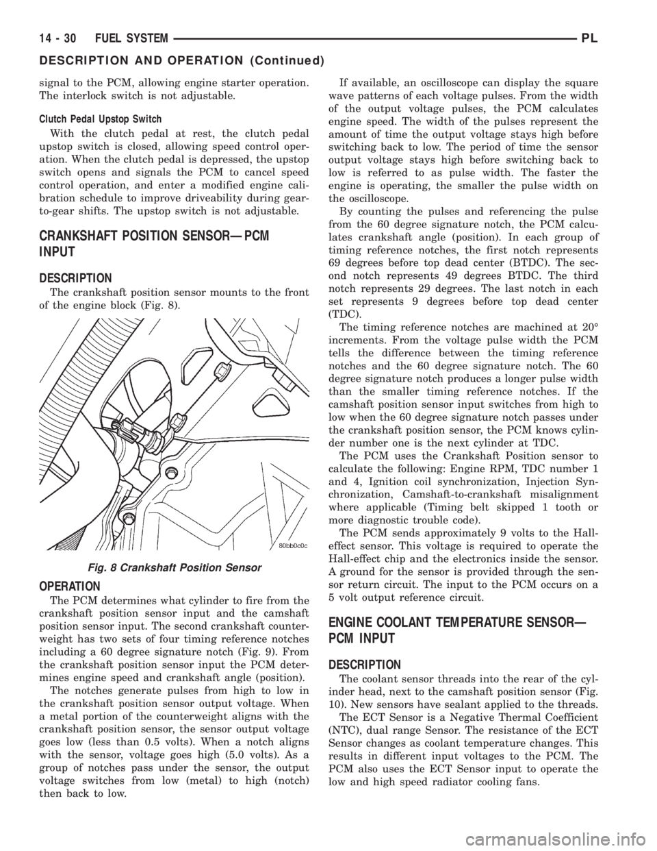
The crankshaft position sensor mounts to the front
of the engine block (Fig. 8).
OPERATION
The PCM determines what cylinder to fire from the
crankshaft position sensor input and the camshaft
position sensor input. The second crankshaft counter-
weight has two sets of four timing reference notches
including a 60 degree signature notch (Fig. 9). From
the crankshaft position sensor input the PCM deter-
mines engine speed and crankshaft angle (position).
The notches generate pulses from high to low in
the crankshaft position sensor output voltage. When
a metal portion of the counterweight aligns with the
crankshaft position sensor, the sensor output voltage
goes low (less than 0.5 volts). When a notch aligns
with the sensor, voltage goes high (5.0 volts). As a
group of notches pass under the sensor, the output
voltage switches from low (metal) to high (notch)
then back to low.If available, an oscilloscope can display the square
wave patterns of each voltage pulses. From the width
of the output voltage pulses, the PCM calculates
engine speed. The width of the pulses represent the
amount of time the output voltage stays high before
switching back to low. The period of time the sensor
output voltage stays high before switching back to
low is referred to as pulse width. The faster the
engine is operating, the smaller the pulse width on
the oscilloscope.
By counting the pulses and referencing the pulse
from the 60 degree signature notch, the PCM calcu-
lates crankshaft angle (position). In each group of
timing reference notches, the first notch represents
69 degrees before top dead center (BTDC). The sec-
ond notch represents 49 degrees BTDC. The third
notch represents 29 degrees. The last notch in each
set represents 9 degrees before top dead center
(TDC).
The timing reference notches are machined at 20É
increments. From the voltage pulse width the PCM
tells the difference between the timing reference
notches and the 60 degree signature notch. The 60
degree signature notch produces a longer pulse width
than the smaller timing reference notches. If the
camshaft position sensor input switches from high to
low when the 60 degree signature notch passes under
the crankshaft position sensor, the PCM knows cylin-
der number one is the next cylinder at TDC.
The PCM uses the Crankshaft Position sensor to
calculate the following: Engine RPM, TDC number 1
and 4, Ignition coil synchronization, Injection Syn-
chronization, Camshaft-to-crankshaft misalignment
where applicable (Timing belt skipped 1 tooth or
more diagnostic trouble code).
The PCM sends approximately 9 volts to the Hall-
effect sensor. This voltage is required to operate the
Hall-effect chip and the electronics inside the sensor.
A ground for the sensor is provided through the sen-
sor return circuit. The input to the PCM occurs on a
5 volt output reference circuit.
ENGINE COOLANT TEMPERATURE SENSORÐ
PCM INPUT
DESCRIPTION
The coolant sensor threads into the rear of the cyl-
inder head, next to the camshaft position sensor (Fig.
10). New sensors have sealant applied to the threads.
The ECT Sensor is a Negative Thermal Coefficient
(NTC), dual range Sensor. The resistance of the ECT
Sensor changes as coolant temperature changes. This
results in different input voltages to the PCM. The
PCM also uses the ECT Sensor input to operate the
low and high speed radiator cooling fans.
Fig. 8 Crankshaft Position Sensor
14 - 30 FUEL SYSTEMPL
DESCRIPTION AND OPERATION (Continued)
Page 862 of 1285
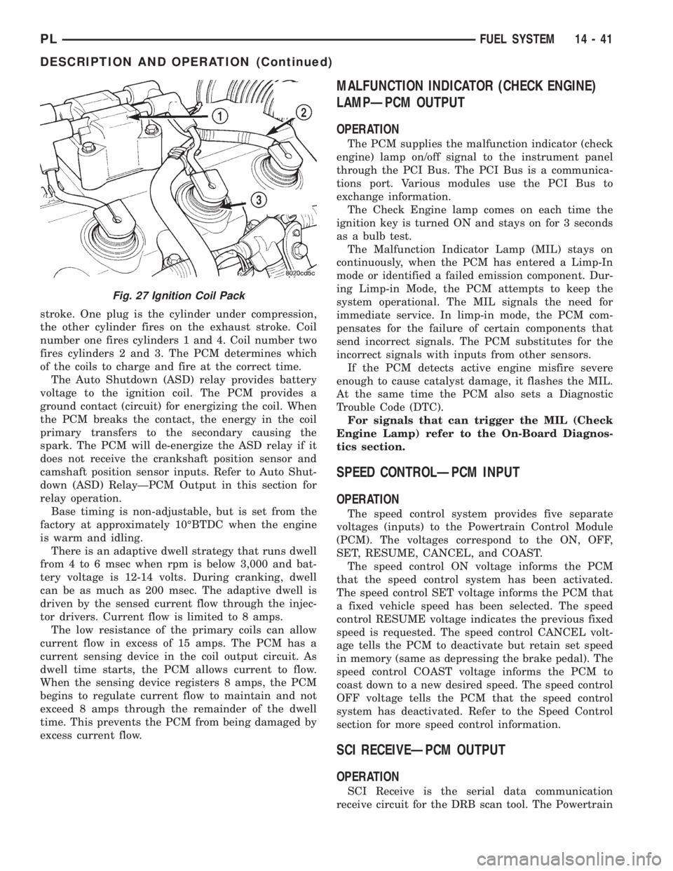
stroke. One plug is the cylinder under compression,
the other cylinder fires on the exhaust stroke. Coil
number one fires cylinders 1 and 4. Coil number two
fires cylinders 2 and 3. The PCM determines which
of the coils to charge and fire at the correct time.
The Auto Shutdown (ASD) relay provides battery
voltage to the ignition coil. The PCM provides a
ground contact (circuit) for energizing the coil. When
the PCM breaks the contact, the energy in the coil
primary transfers to the secondary causing the
spark. The PCM will de-energize the ASD relay if it
does not receive the crankshaft position sensor and
camshaft position sensor inputs. Refer to Auto Shut-
down (ASD) RelayÐPCM Output in this section for
relay operation.
Base timing is non-adjustable, but is set from the
factory at approximately 10ÉBTDC when the engine
is warm and idling.
There is an adaptive dwell strategy that runs dwell
from 4 to 6 msec when rpm is below 3,000 and bat-
tery voltage is 12-14 volts. During cranking, dwell
can be as much as 200 msec. The adaptive dwell is
driven by the sensed current flow through the injec-
tor drivers. Current flow is limited to 8 amps.
The low resistance of the primary coils can allow
current flow in excess of 15 amps. The PCM has a
current sensing device in the coil output circuit. As
dwell time starts, the PCM allows current to flow.
When the sensing device registers 8 amps, the PCM
begins to regulate current flow to maintain and not
exceed 8 amps through the remainder of the dwell
time. This prevents the PCM from being damaged by
excess current flow.
MALFUNCTION INDICATOR (CHECK ENGINE)
LAMPÐPCM OUTPUT
OPERATION
The PCM supplies the malfunction indicator (check
engine) lamp on/off signal to the instrument panel
through the PCI Bus. The PCI Bus is a communica-
tions port. Various modules use the PCI Bus to
exchange information.
The Check Engine lamp comes on each time the
ignition key is turned ON and stays on for 3 seconds
as a bulb test.
The Malfunction Indicator Lamp (MIL) stays on
continuously, when the PCM has entered a Limp-In
mode or identified a failed emission component. Dur-
ing Limp-in Mode, the PCM attempts to keep the
system operational. The MIL signals the need for
immediate service. In limp-in mode, the PCM com-
pensates for the failure of certain components that
send incorrect signals. The PCM substitutes for the
incorrect signals with inputs from other sensors.
If the PCM detects active engine misfire severe
enough to cause catalyst damage, it flashes the MIL.
At the same time the PCM also sets a Diagnostic
Trouble Code (DTC).
For signals that can trigger the MIL (Check
Engine Lamp) refer to the On-Board Diagnos-
tics section.
SPEED CONTROLÐPCM INPUT
OPERATION
The speed control system provides five separate
voltages (inputs) to the Powertrain Control Module
(PCM). The voltages correspond to the ON, OFF,
SET, RESUME, CANCEL, and COAST.
The speed control ON voltage informs the PCM
that the speed control system has been activated.
The speed control SET voltage informs the PCM that
a fixed vehicle speed has been selected. The speed
control RESUME voltage indicates the previous fixed
speed is requested. The speed control CANCEL volt-
age tells the PCM to deactivate but retain set speed
in memory (same as depressing the brake pedal). The
speed control COAST voltage informs the PCM to
coast down to a new desired speed. The speed control
OFF voltage tells the PCM that the speed control
system has deactivated. Refer to the Speed Control
section for more speed control information.
SCI RECEIVEÐPCM OUTPUT
OPERATION
SCI Receive is the serial data communication
receive circuit for the DRB scan tool. The Powertrain
Fig. 27 Ignition Coil Pack
PLFUEL SYSTEM 14 - 41
DESCRIPTION AND OPERATION (Continued)
Page 915 of 1285
ferential case transfers torque from the ring gear to the
drive axles by means of differential side gears.
The NV T350 (A-578) transaxle internal components
can only be serviced by separating the case halves.
CAUTION: The transaxle output shaft is serviced as
a unit. No disassembly and reassembly is possible.
Damage to the transaxle may result.
TRANSAXLE IDENTIFICATION
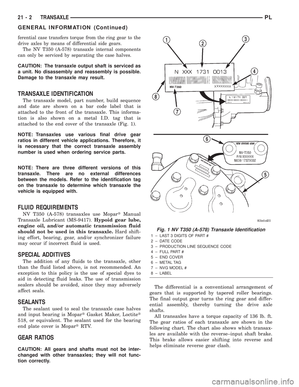
The transaxle model, part number, build sequence
and date are shown on a bar code label that is
attached to the front of the transaxle. This informa-
tion is also shown on a metal I.D. tag that is
attached to the end cover of the transaxle (Fig. 1).
NOTE: Transaxles use various final drive gear
ratios in different vehicle applications. Therefore, it
is necessary that the correct transaxle assembly
number is used when ordering service parts.
NOTE: There are three different versions of this
transaxle. There are no external differences
between the models. Refer to the identification tag
on the transaxle to determine which transaxle the
vehicle is equipped with.
FLUID REQUIREMENTS
NV T350 (A-578) transaxles use MopartManual
Transaxle Lubricant (MS-9417).Hypoid gear lube,
engine oil, and/or automatic transmission fluid
should not be used in this transaxle.Hard shift-
ing effort, bearing, gear, and/or synchronizer failure
may occur if incorrect fluid is used.
SPECIAL ADDITIVES
The addition of any fluids to the transaxle, other
than the fluid listed above, is not recommended. An
exception to this policy is the use of special dyes to
aid in detecting fluid leaks. The use of transmission
sealers should be avoided, since they may adversely
affect seals.
SEALANTS
The sealant used to seal the transaxle case halves
and input bearing is MopartGasket Maker, Loctitet
518, or equivalent. The sealant used for the bearing
end plate cover is MopartRTV.
GEAR RATIOS
CAUTION: All gears and shafts must not be inter-
changed with other transaxles; they will not func-
tion correctly.The differential is a conventional arrangement of
gears that is supported by tapered roller bearings.
The final output gear turns the ring gear and differ-
ential assembly, thereby turning the drive axle
shafts.
All transaxles have a torque capacity of 136 lb. ft.
The gear ratios of each transaxle are shown in the
following chart. The chart also shows which transax-
les are available with the reverse±input shaft brake.
This brake allows easier shifting into reverse and
helps eliminate reverse gear clash.
Fig. 1 NV T350 (A-578) Transaxle Identification
1 ± LAST 3 DIGITS OF PART #
2 ± DATE CODE
3 ± PRODUCTION LINE SEQUENCE CODE
4 ± FULL PART #
5 ± END COVER
6 ± METAL TAG
7 ± NVG MODEL #
8 ± LABEL
21 - 2 TRANSAXLEPL
GENERAL INFORMATION (Continued)
Page 968 of 1285
GENERAL INFORMATION
IN VEHICLE SERVICE
The following components are serviceable in the
vehicle without transaxle removal:
²Valve Body Assembly
²Converter Clutch Solenoid
²Governor
²Vehicle Speed Sensor & Pinion
²Park/Neutral & Back-up Lamp Switch
²Transfer Gears and Transfer Shaft
²Low/Reverse Servo
²Kickdown Servo
²Accumulator
FLUID REQUIREMENTS
NOTE: The transmission and differential have a
common oil sump with an opening between the
two.
TRANSMISSION/DIFFERENTIAL
MopartATF+4 (Automatic Transmission Fluid
Type 9602) is required in this transaxle. Substitute
fluids must meet fluid specification MS-9602.
FLUID ADDITIVES
Chrysler Corporation strongly recommends against
the addition of any fluids to the transmission, other
than those automatic transmission fluids listed
above. Exceptions to this policy are the use of special
dyes to aid in detecting fluid leaks.
Various ªspecialº additives and supplements exist
that claim to improve shift feel/quality and converter
clutch operation, inhibit overheating, oxidation, var-
nish and sludge. These claims have not been sup-
ported to Chrysler's satisfaction and these additives
must not be used. The use of transmission ªsealersº
should also be avoided, since they may adversely
affect the integrity of tranmission seals.
DESCRIPTION AND OPERATION
31TH GENERAL INFORMATION
NOTE: Safety goggles should be worn at all times
when working on these transaxles.
This transaxle combines torque converter, three
speed transmission, final drive gearing, and differen-
tial into a front wheel drive system.
NOTE: Transaxle operation requirements are differ-
ent for each vehicle and engine combination. Some
internal parts will be different to provide for this.Therefore, when replacing parts, refer to the seven
digit part number stamped on rear of the transaxle
oil pan flange.
Within this transaxle, there are three primary
areas:
(1) Main center line plus valve body.
(2) Transfer shaft center line (includes governor
and parking sprag).
(3) Differential center line.
Center distances between the main rotating parts
in these three areas are held precise to maintain a
low noise level.
The torque converter, transaxle area, and differen-
tial are housed in an integral aluminum die casting.
The differential oil sump is common with the
transaxle sump. Separate filling of the differen-
tial is NOT necessary.
The torque converter is attached to the crankshaft
through a flexible driving plate. Cooling of the con-
verter is accomplished by circulating the transaxle
fluid through a remote cooler. There are two types of
coolers used. An oil-to-water type cooler located in
the radiator side tank and/or an oil-to-air heat
exchanger. The torque converter assembly is a sealed
unit that cannot be disassembled.
The transaxle fluid is filtered by an internal filter
attached to the lower side of the valve body assembly.
Engine torque is transmitted to the torque con-
verter and then through the input shaft to multiple-
disc clutches in the transaxle. The power flow
depends on the application of the clutches and bands.
Refer to Elements in Use Chart in Diagnosis and
Tests section.
The transaxle consists of:
²Two multiple-disc clutches
²An overrunning clutch
²Two servos
²A hydraulic accumulator
²Two bands
²Two planetary gear sets
This provides three forward ratios and a reverse
ratio. The common sun gear of the planetary gear
sets is connected to the front clutch by a driving
shell. The driving shell is splined to the sun gear and
front clutch retainer. The hydraulic system consists
of an oil pump and a single valve body which con-
tains all of the valves except the governor valves.
The transaxle sump and differential sump are both
vented through the dipstick. Output torque from the
main center line is delivered through helical gears to
the transfer shaft. This gear set is a factor in the
transaxle final drive (axle) ratio. The shaft also car-
ries the governor and parking sprag. An integral heli-
cal gear on the transfer shaft drives the differential
ring gear.
PLTRANSAXLE 21 - 55