2000 DODGE NEON oil change
[x] Cancel search: oil changePage 193 of 1285
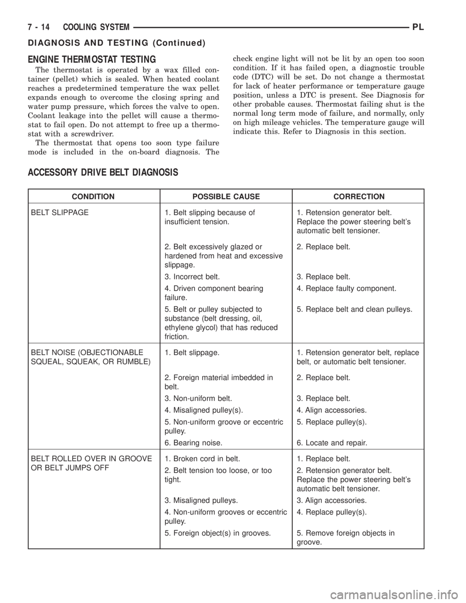
ENGINE THERMOSTAT TESTING
The thermostat is operated by a wax filled con-
tainer (pellet) which is sealed. When heated coolant
reaches a predetermined temperature the wax pellet
expands enough to overcome the closing spring and
water pump pressure, which forces the valve to open.
Coolant leakage into the pellet will cause a thermo-
stat to fail open. Do not attempt to free up a thermo-
stat with a screwdriver.
The thermostat that opens too soon type failure
mode is included in the on-board diagnosis. Thecheck engine light will not be lit by an open too soon
condition. If it has failed open, a diagnostic trouble
code (DTC) will be set. Do not change a thermostat
for lack of heater performance or temperature gauge
position, unless a DTC is present. See Diagnosis for
other probable causes. Thermostat failing shut is the
normal long term mode of failure, and normally, only
on high mileage vehicles. The temperature gauge will
indicate this. Refer to Diagnosis in this section.
ACCESSORY DRIVE BELT DIAGNOSIS
CONDITION POSSIBLE CAUSE CORRECTION
BELT SLIPPAGE 1. Belt slipping because of
insufficient tension.1. Retension generator belt.
Replace the power steering belt's
automatic belt tensioner.
2. Belt excessively glazed or
hardened from heat and excessive
slippage.2. Replace belt.
3. Incorrect belt. 3. Replace belt.
4. Driven component bearing
failure.4. Replace faulty component.
5. Belt or pulley subjected to
substance (belt dressing, oil,
ethylene glycol) that has reduced
friction.5. Replace belt and clean pulleys.
BELT NOISE (OBJECTIONABLE
SQUEAL, SQUEAK, OR RUMBLE)1. Belt slippage. 1. Retension generator belt, replace
belt, or automatic belt tensioner.
2. Foreign material imbedded in
belt.2. Replace belt.
3. Non-uniform belt. 3. Replace belt.
4. Misaligned pulley(s). 4. Align accessories.
5. Non-uniform groove or eccentric
pulley.5. Replace pulley(s).
6. Bearing noise. 6. Locate and repair.
BELT ROLLED OVER IN GROOVE
OR BELT JUMPS OFF1. Broken cord in belt. 1. Replace belt.
2. Belt tension too loose, or too
tight.2. Retension generator belt.
Replace the power steering belt's
automatic belt tensioner.
3. Misaligned pulleys. 3. Align accessories.
4. Non-uniform grooves or eccentric
pulley.4. Replace pulley(s).
5. Foreign object(s) in grooves. 5. Remove foreign objects in
groove.
7 - 14 COOLING SYSTEMPL
DIAGNOSIS AND TESTING (Continued)
Page 308 of 1285
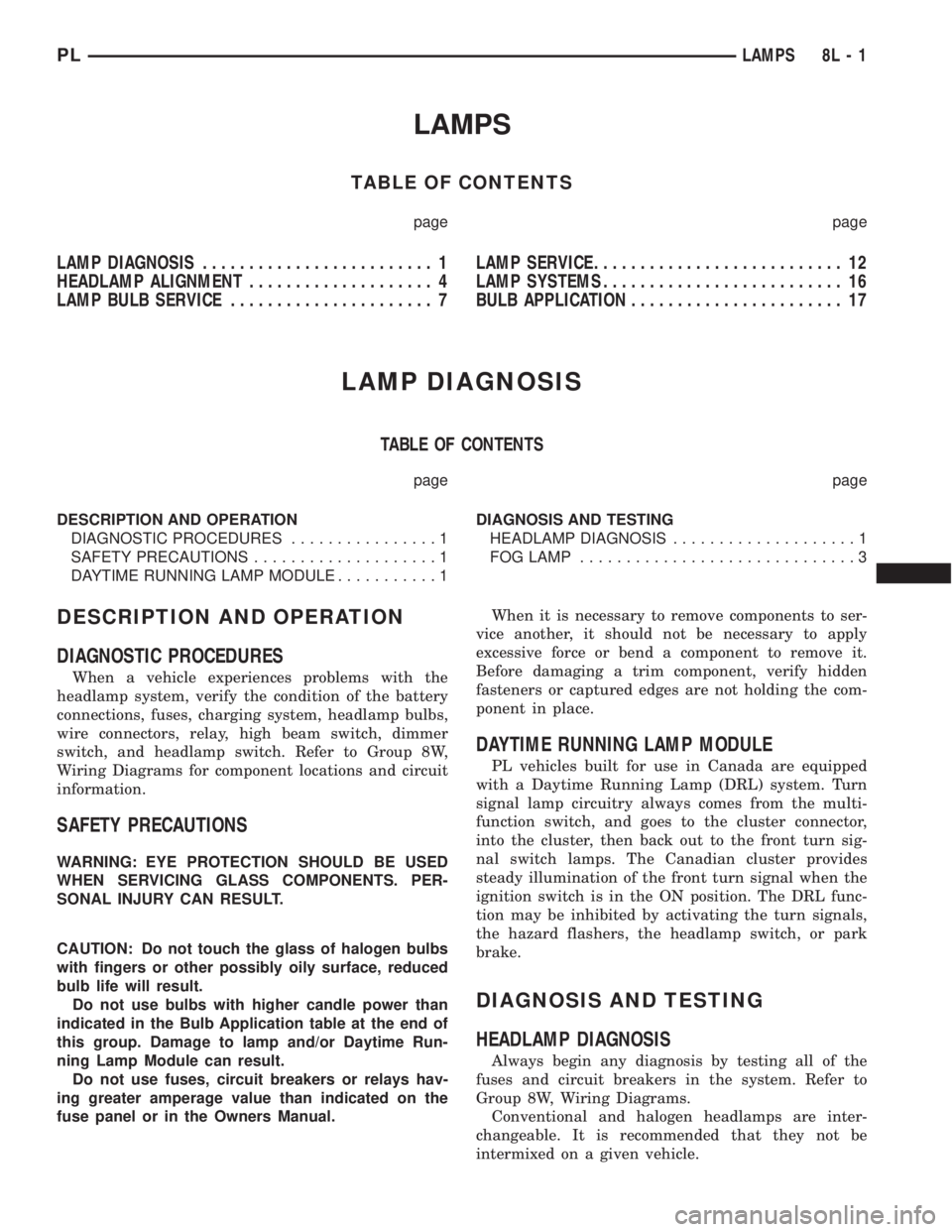
LAMPS
TABLE OF CONTENTS
page page
LAMP DIAGNOSIS......................... 1
HEADLAMP ALIGNMENT.................... 4
LAMP BULB SERVICE...................... 7LAMP SERVICE........................... 12
LAMP SYSTEMS.......................... 16
BULB APPLICATION....................... 17
LAMP DIAGNOSIS
TABLE OF CONTENTS
page page
DESCRIPTION AND OPERATION
DIAGNOSTIC PROCEDURES................1
SAFETY PRECAUTIONS....................1
DAYTIME RUNNING LAMP MODULE...........1DIAGNOSIS AND TESTING
HEADLAMP DIAGNOSIS....................1
FOG LAMP..............................3
DESCRIPTION AND OPERATION
DIAGNOSTIC PROCEDURES
When a vehicle experiences problems with the
headlamp system, verify the condition of the battery
connections, fuses, charging system, headlamp bulbs,
wire connectors, relay, high beam switch, dimmer
switch, and headlamp switch. Refer to Group 8W,
Wiring Diagrams for component locations and circuit
information.
SAFETY PRECAUTIONS
WARNING: EYE PROTECTION SHOULD BE USED
WHEN SERVICING GLASS COMPONENTS. PER-
SONAL INJURY CAN RESULT.
CAUTION: Do not touch the glass of halogen bulbs
with fingers or other possibly oily surface, reduced
bulb life will result.
Do not use bulbs with higher candle power than
indicated in the Bulb Application table at the end of
this group. Damage to lamp and/or Daytime Run-
ning Lamp Module can result.
Do not use fuses, circuit breakers or relays hav-
ing greater amperage value than indicated on the
fuse panel or in the Owners Manual.When it is necessary to remove components to ser-
vice another, it should not be necessary to apply
excessive force or bend a component to remove it.
Before damaging a trim component, verify hidden
fasteners or captured edges are not holding the com-
ponent in place.
DAYTIME RUNNING LAMP MODULE
PL vehicles built for use in Canada are equipped
with a Daytime Running Lamp (DRL) system. Turn
signal lamp circuitry always comes from the multi-
function switch, and goes to the cluster connector,
into the cluster, then back out to the front turn sig-
nal switch lamps. The Canadian cluster provides
steady illumination of the front turn signal when the
ignition switch is in the ON position. The DRL func-
tion may be inhibited by activating the turn signals,
the hazard flashers, the headlamp switch, or park
brake.
DIAGNOSIS AND TESTING
HEADLAMP DIAGNOSIS
Always begin any diagnosis by testing all of the
fuses and circuit breakers in the system. Refer to
Group 8W, Wiring Diagrams.
Conventional and halogen headlamps are inter-
changeable. It is recommended that they not be
intermixed on a given vehicle.
PLLAMPS 8L - 1
Page 730 of 1285
ENGINE OIL SERVICE
WARNING: NEW OR USED ENGINE OIL CAN BE
IRRITATING TO THE SKIN. AVOID PROLONGED OR
REPEATED SKIN CONTACT WITH ENGINE OIL.
CONTAMINANTS IN USED ENGINE OIL, CAUSED BY
INTERNAL COMBUSTION, CAN BE HAZARDOUS TO
YOUR HEALTH. THOROUGHLY WASH EXPOSED
SKIN WITH SOAP AND WATER. DO NOT WASH
SKIN WITH GASOLINE, DIESEL FUEL, THINNER, OR
SOLVENTS, HEALTH PROBLEMS CAN RESULT. DO
NOT POLLUTE, DISPOSE OF USED ENGINE OIL
PROPERLY. CONTACT YOUR DEALER OR GOVERN-
MENT AGENCY FOR LOCATION OF COLLECTION
CENTER IN YOUR AREA.
ENGINE OIL SPECIFICATION
CAUTION: Do not use non-detergent or straight
mineral oil when adding or changing crankcase
lubricant. Engine failure can result.
API SERVICE GRADE CERTIFIED
Use an engine oil that is API Service Grade Certi-
fied. MOPARtprovides engine oils that conforms to
this service grade.
SAE VISCOSITY
An SAE viscosity grade is used to specify the vis-
cosity of engine oil. Use only, engine oils with multi-
ple viscosities such as 5W-30 or 10W-30. These are
specified with a dual SAE viscosity grade which indi-
cates the cold-to-hot temperature viscosity range.
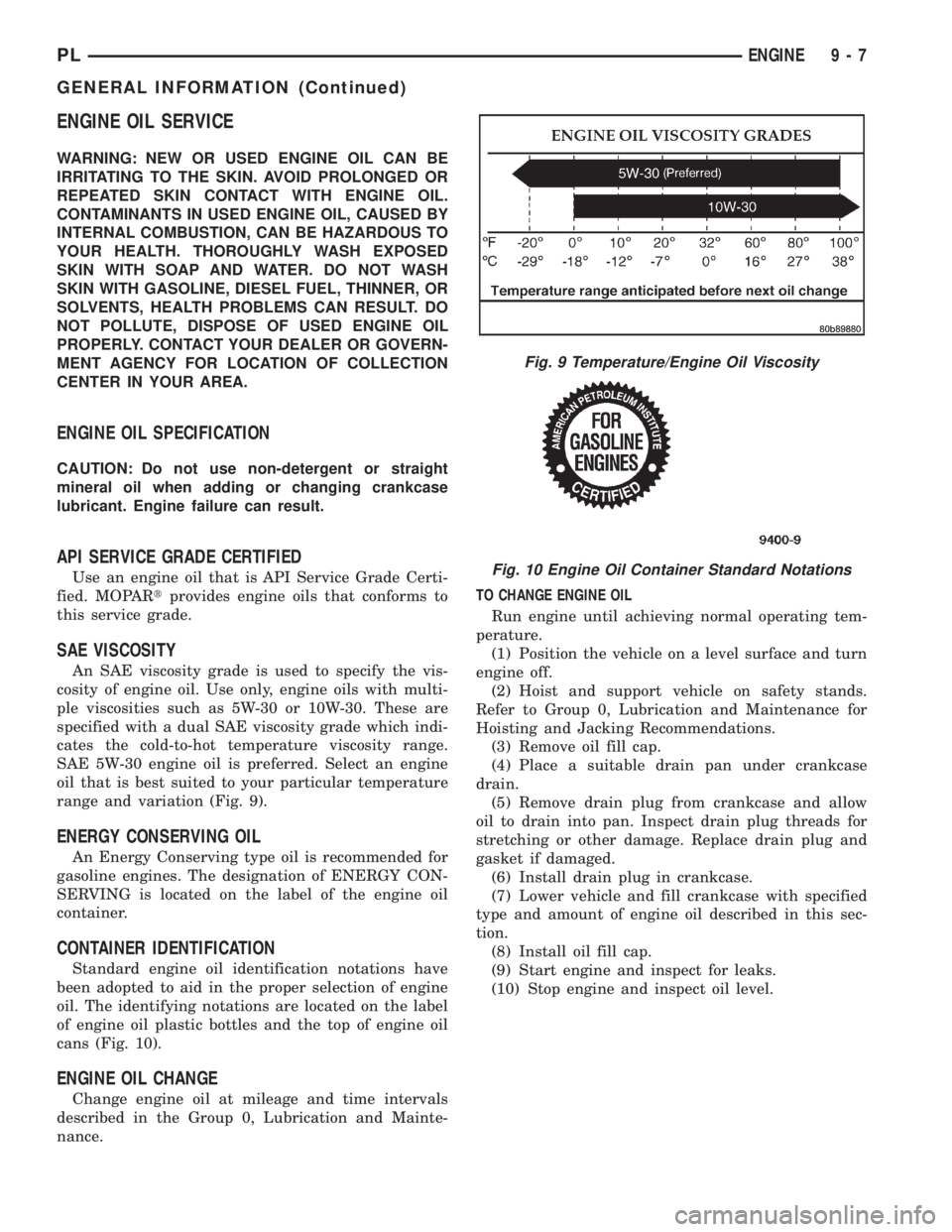
SAE 5W-30 engine oil is preferred. Select an engine
oil that is best suited to your particular temperature
range and variation (Fig. 9).
ENERGY CONSERVING OIL
An Energy Conserving type oil is recommended for
gasoline engines. The designation of ENERGY CON-
SERVING is located on the label of the engine oil
container.
CONTAINER IDENTIFICATION
Standard engine oil identification notations have
been adopted to aid in the proper selection of engine
oil. The identifying notations are located on the label
of engine oil plastic bottles and the top of engine oil
cans (Fig. 10).
ENGINE OIL CHANGE
Change engine oil at mileage and time intervals
described in the Group 0, Lubrication and Mainte-
nance.TO CHANGE ENGINE OIL
Run engine until achieving normal operating tem-
perature.
(1) Position the vehicle on a level surface and turn
engine off.
(2) Hoist and support vehicle on safety stands.
Refer to Group 0, Lubrication and Maintenance for
Hoisting and Jacking Recommendations.
(3) Remove oil fill cap.
(4) Place a suitable drain pan under crankcase
drain.
(5) Remove drain plug from crankcase and allow
oil to drain into pan. Inspect drain plug threads for
stretching or other damage. Replace drain plug and
gasket if damaged.
(6) Install drain plug in crankcase.
(7) Lower vehicle and fill crankcase with specified
type and amount of engine oil described in this sec-
tion.
(8) Install oil fill cap.
(9) Start engine and inspect for leaks.
(10) Stop engine and inspect oil level.
Fig. 9 Temperature/Engine Oil Viscosity
Fig. 10 Engine Oil Container Standard Notations
PLENGINE 9 - 7
GENERAL INFORMATION (Continued)
Page 731 of 1285
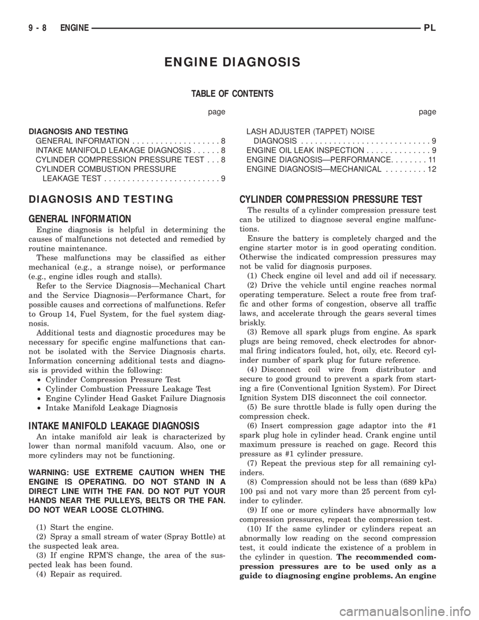
ENGINE DIAGNOSIS
TABLE OF CONTENTS
page page
DIAGNOSIS AND TESTING
GENERAL INFORMATION...................8
INTAKE MANIFOLD LEAKAGE DIAGNOSIS......8
CYLINDER COMPRESSION PRESSURE TEST . . . 8
CYLINDER COMBUSTION PRESSURE
LEAKAGE TEST.........................9LASH ADJUSTER (TAPPET) NOISE
DIAGNOSIS............................9
ENGINE OIL LEAK INSPECTION..............9
ENGINE DIAGNOSISÐPERFORMANCE........11
ENGINE DIAGNOSISÐMECHANICAL.........12
DIAGNOSIS AND TESTING
GENERAL INFORMATION
Engine diagnosis is helpful in determining the
causes of malfunctions not detected and remedied by
routine maintenance.
These malfunctions may be classified as either
mechanical (e.g., a strange noise), or performance
(e.g., engine idles rough and stalls).
Refer to the Service DiagnosisÐMechanical Chart
and the Service DiagnosisÐPerformance Chart, for
possible causes and corrections of malfunctions. Refer
to Group 14, Fuel System, for the fuel system diag-
nosis.
Additional tests and diagnostic procedures may be
necessary for specific engine malfunctions that can-
not be isolated with the Service Diagnosis charts.
Information concerning additional tests and diagno-
sis is provided within the following:
²Cylinder Compression Pressure Test
²Cylinder Combustion Pressure Leakage Test
²Engine Cylinder Head Gasket Failure Diagnosis
²Intake Manifold Leakage Diagnosis
INTAKE MANIFOLD LEAKAGE DIAGNOSIS
An intake manifold air leak is characterized by
lower than normal manifold vacuum. Also, one or
more cylinders may not be functioning.
WARNING: USE EXTREME CAUTION WHEN THE
ENGINE IS OPERATING. DO NOT STAND IN A
DIRECT LINE WITH THE FAN. DO NOT PUT YOUR
HANDS NEAR THE PULLEYS, BELTS OR THE FAN.
DO NOT WEAR LOOSE CLOTHING.
(1) Start the engine.
(2) Spray a small stream of water (Spray Bottle) at
the suspected leak area.
(3) If engine RPM'S change, the area of the sus-
pected leak has been found.
(4) Repair as required.
CYLINDER COMPRESSION PRESSURE TEST
The results of a cylinder compression pressure test
can be utilized to diagnose several engine malfunc-
tions.
Ensure the battery is completely charged and the
engine starter motor is in good operating condition.
Otherwise the indicated compression pressures may
not be valid for diagnosis purposes.
(1) Check engine oil level and add oil if necessary.
(2) Drive the vehicle until engine reaches normal
operating temperature. Select a route free from traf-
fic and other forms of congestion, observe all traffic
laws, and accelerate through the gears several times
briskly.
(3) Remove all spark plugs from engine. As spark
plugs are being removed, check electrodes for abnor-
mal firing indicators fouled, hot, oily, etc. Record cyl-
inder number of spark plug for future reference.
(4) Disconnect coil wire from distributor and
secure to good ground to prevent a spark from start-
ing a fire (Conventional Ignition System). For Direct
Ignition System DIS disconnect the coil connector.
(5) Be sure throttle blade is fully open during the
compression check.
(6) Insert compression gage adaptor into the #1
spark plug hole in cylinder head. Crank engine until
maximum pressure is reached on gage. Record this
pressure as #1 cylinder pressure.
(7) Repeat the previous step for all remaining cyl-
inders.
(8) Compression should not be less than (689 kPa)
100 psi and not vary more than 25 percent from cyl-
inder to cylinder.
(9) If one or more cylinders have abnormally low
compression pressures, repeat the compression test.
(10) If the same cylinder or cylinders repeat an
abnormally low reading on the second compression
test, it could indicate the existence of a problem in
the cylinder in question.The recommended com-
pression pressures are to be used only as a
guide to diagnosing engine problems. An engine
9 - 8 ENGINEPL
Page 735 of 1285
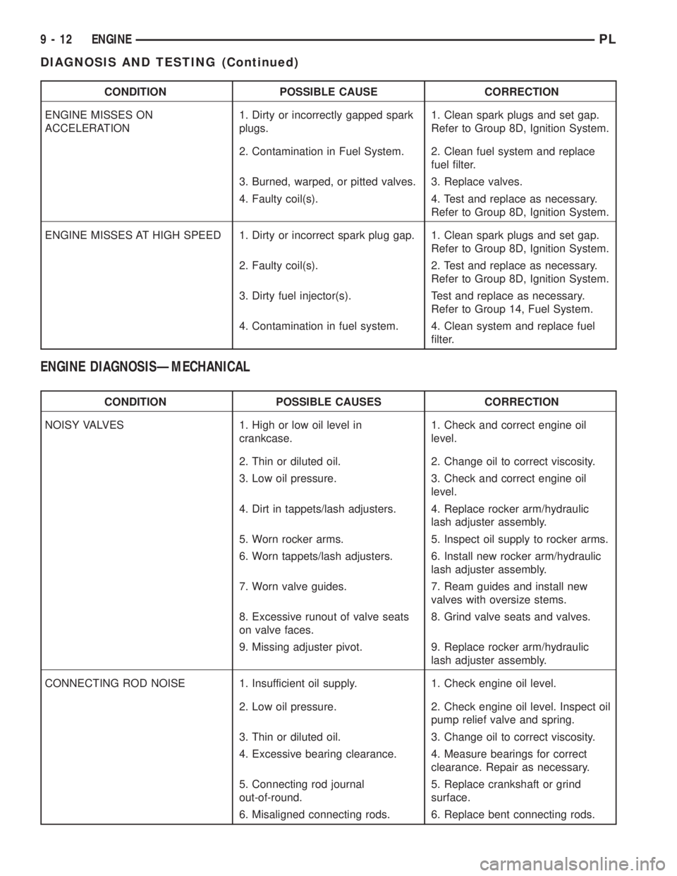
CONDITION POSSIBLE CAUSE CORRECTION
ENGINE MISSES ON
ACCELERATION1. Dirty or incorrectly gapped spark
plugs.1. Clean spark plugs and set gap.
Refer to Group 8D, Ignition System.
2. Contamination in Fuel System. 2. Clean fuel system and replace
fuel filter.
3. Burned, warped, or pitted valves. 3. Replace valves.
4. Faulty coil(s). 4. Test and replace as necessary.
Refer to Group 8D, Ignition System.
ENGINE MISSES AT HIGH SPEED 1. Dirty or incorrect spark plug gap. 1. Clean spark plugs and set gap.
Refer to Group 8D, Ignition System.
2. Faulty coil(s). 2. Test and replace as necessary.
Refer to Group 8D, Ignition System.
3. Dirty fuel injector(s). Test and replace as necessary.
Refer to Group 14, Fuel System.
4. Contamination in fuel system. 4. Clean system and replace fuel
filter.
ENGINE DIAGNOSISÐMECHANICAL
CONDITION POSSIBLE CAUSES CORRECTION
NOISY VALVES 1. High or low oil level in
crankcase.1. Check and correct engine oil
level.
2. Thin or diluted oil. 2. Change oil to correct viscosity.
3. Low oil pressure. 3. Check and correct engine oil
level.
4. Dirt in tappets/lash adjusters. 4. Replace rocker arm/hydraulic
lash adjuster assembly.
5. Worn rocker arms. 5. Inspect oil supply to rocker arms.
6. Worn tappets/lash adjusters. 6. Install new rocker arm/hydraulic
lash adjuster assembly.
7. Worn valve guides. 7. Ream guides and install new
valves with oversize stems.
8. Excessive runout of valve seats
on valve faces.8. Grind valve seats and valves.
9. Missing adjuster pivot. 9. Replace rocker arm/hydraulic
lash adjuster assembly.
CONNECTING ROD NOISE 1. Insufficient oil supply. 1. Check engine oil level.
2. Low oil pressure. 2. Check engine oil level. Inspect oil
pump relief valve and spring.
3. Thin or diluted oil. 3. Change oil to correct viscosity.
4. Excessive bearing clearance. 4. Measure bearings for correct
clearance. Repair as necessary.
5. Connecting rod journal
out-of-round.5. Replace crankshaft or grind
surface.
6. Misaligned connecting rods. 6. Replace bent connecting rods.
9 - 12 ENGINEPL
DIAGNOSIS AND TESTING (Continued)
Page 736 of 1285
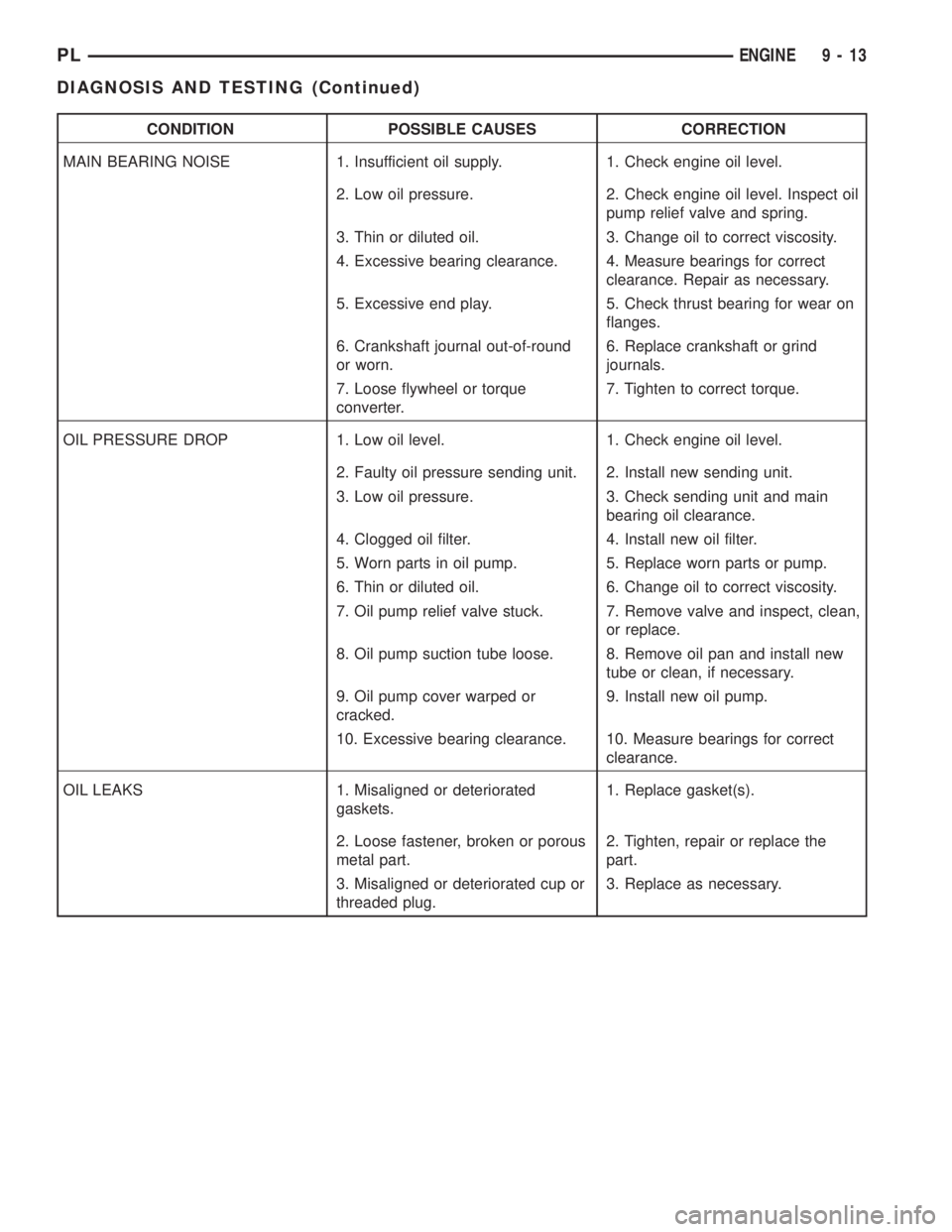
CONDITION POSSIBLE CAUSES CORRECTION
MAIN BEARING NOISE 1. Insufficient oil supply. 1. Check engine oil level.
2. Low oil pressure. 2. Check engine oil level. Inspect oil
pump relief valve and spring.
3. Thin or diluted oil. 3. Change oil to correct viscosity.
4. Excessive bearing clearance. 4. Measure bearings for correct
clearance. Repair as necessary.
5. Excessive end play. 5. Check thrust bearing for wear on
flanges.
6. Crankshaft journal out-of-round
or worn.6. Replace crankshaft or grind
journals.
7. Loose flywheel or torque
converter.7. Tighten to correct torque.
OIL PRESSURE DROP 1. Low oil level. 1. Check engine oil level.
2. Faulty oil pressure sending unit. 2. Install new sending unit.
3. Low oil pressure. 3. Check sending unit and main
bearing oil clearance.
4. Clogged oil filter. 4. Install new oil filter.
5. Worn parts in oil pump. 5. Replace worn parts or pump.
6. Thin or diluted oil. 6. Change oil to correct viscosity.
7. Oil pump relief valve stuck. 7. Remove valve and inspect, clean,
or replace.
8. Oil pump suction tube loose. 8. Remove oil pan and install new
tube or clean, if necessary.
9. Oil pump cover warped or
cracked.9. Install new oil pump.
10. Excessive bearing clearance. 10. Measure bearings for correct
clearance.
OIL LEAKS 1. Misaligned or deteriorated
gaskets.1. Replace gasket(s).
2. Loose fastener, broken or porous
metal part.2. Tighten, repair or replace the
part.
3. Misaligned or deteriorated cup or
threaded plug.3. Replace as necessary.
PLENGINE 9 - 13
DIAGNOSIS AND TESTING (Continued)
Page 739 of 1285
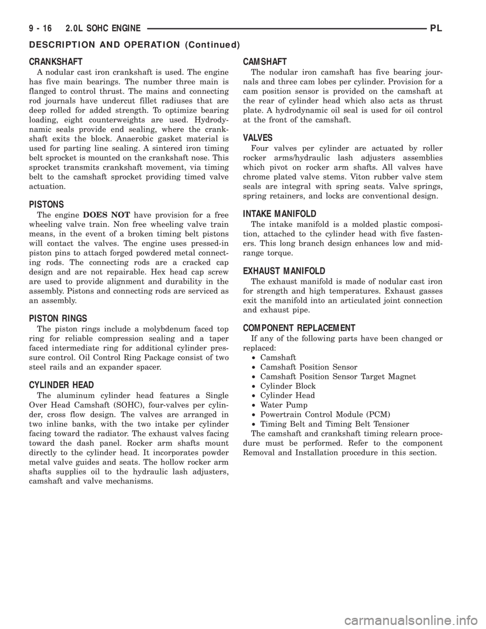
CRANKSHAFT
A nodular cast iron crankshaft is used. The engine
has five main bearings. The number three main is
flanged to control thrust. The mains and connecting
rod journals have undercut fillet radiuses that are
deep rolled for added strength. To optimize bearing
loading, eight counterweights are used. Hydrody-
namic seals provide end sealing, where the crank-
shaft exits the block. Anaerobic gasket material is
used for parting line sealing. A sintered iron timing
belt sprocket is mounted on the crankshaft nose. This
sprocket transmits crankshaft movement, via timing
belt to the camshaft sprocket providing timed valve
actuation.
PISTONS
The engineDOES NOThave provision for a free
wheeling valve train. Non free wheeling valve train
means, in the event of a broken timing belt pistons
will contact the valves. The engine uses pressed-in
piston pins to attach forged powdered metal connect-
ing rods. The connecting rods are a cracked cap
design and are not repairable. Hex head cap screw
are used to provide alignment and durability in the
assembly. Pistons and connecting rods are serviced as
an assembly.
PISTON RINGS
The piston rings include a molybdenum faced top
ring for reliable compression sealing and a taper
faced intermediate ring for additional cylinder pres-
sure control. Oil Control Ring Package consist of two
steel rails and an expander spacer.
CYLINDER HEAD
The aluminum cylinder head features a Single
Over Head Camshaft (SOHC), four-valves per cylin-
der, cross flow design. The valves are arranged in
two inline banks, with the two intake per cylinder
facing toward the radiator. The exhaust valves facing
toward the dash panel. Rocker arm shafts mount
directly to the cylinder head. It incorporates powder
metal valve guides and seats. The hollow rocker arm
shafts supplies oil to the hydraulic lash adjusters,
camshaft and valve mechanisms.
CAMSHAFT
The nodular iron camshaft has five bearing jour-
nals and three cam lobes per cylinder. Provision for a
cam position sensor is provided on the camshaft at
the rear of cylinder head which also acts as thrust
plate. A hydrodynamic oil seal is used for oil control
at the front of the camshaft.
VALVES
Four valves per cylinder are actuated by roller
rocker arms/hydraulic lash adjusters assemblies
which pivot on rocker arm shafts. All valves have
chrome plated valve stems. Viton rubber valve stem
seals are integral with spring seats. Valve springs,
spring retainers, and locks are conventional design.
INTAKE MANIFOLD
The intake manifold is a molded plastic composi-
tion, attached to the cylinder head with five fasten-
ers. This long branch design enhances low and mid-
range torque.
EXHAUST MANIFOLD
The exhaust manifold is made of nodular cast iron
for strength and high temperatures. Exhaust gasses
exit the manifold into an articulated joint connection
and exhaust pipe.
COMPONENT REPLACEMENT
If any of the following parts have been changed or
replaced:
²Camshaft
²Camshaft Position Sensor
²Camshaft Position Sensor Target Magnet
²Cylinder Block
²Cylinder Head
²Water Pump
²Powertrain Control Module (PCM)
²Timing Belt and Timing Belt Tensioner
The camshaft and crankshaft timing relearn proce-
dure must be performed. Refer to the component
Removal and Installation procedure in this section.
9 - 16 2.0L SOHC ENGINEPL
DESCRIPTION AND OPERATION (Continued)
Page 776 of 1285
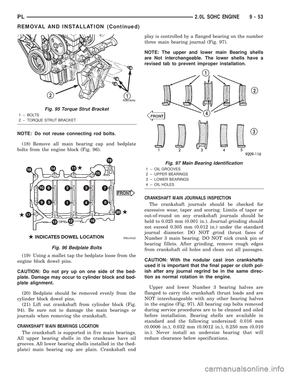
NOTE: Do not reuse connecting rod bolts.
(18) Remove all main bearing cap and bedplate
bolts from the engine block (Fig. 96).
(19) Using a mallet tap the bedplate loose from the
engine block dowel pins.
CAUTION: Do not pry up on one side of the bed-
plate. Damage may occur to cylinder block and bed-
plate alignment.
(20) Bedplate should be removed evenly from the
cylinder block dowel pins.
(21) Lift out crankshaft from cylinder block (Fig.
94). Be sure not to damage the main bearings or
journals when removing the crankshaft.
CRANKSHAFT MAIN BEARINGS LOCATION
The crankshaft is supported in five main bearings.
All upper bearing shells in the crankcase have oil
grooves. All lower bearing shells installed in the (bed-
plate) main bearing cap are plain. Crankshaft endplay is controlled by a flanged bearing on the number
three main bearing journal (Fig. 97).
NOTE: The upper and lower main Bearing shells
are Not interchangeable. The lower shells have a
revised tab to prevent improper installation.
CRANKSHAFT MAIN JOURNALS INSPECTION
The crankshaft journals should be checked for
excessive wear, taper and scoring. Limits of taper or
out-of-round on any crankshaft journals should be
held to 0.025 mm (0.001 in.). Journal grinding should
not exceed 0.305 mm (0.012 in.) under the standard
journal diameter. DO NOT grind thrust faces of
Number 3 main bearing. DO NOT nick crank pin or
bearing fillets. After grinding, remove rough edges
from crankshaft oil holes and clean out all passages.
CAUTION: With the nodular cast iron crankshafts
used it is important that the final paper or cloth pol-
ish after any journal regrind be in the same direc-
tion as normal rotation in the engine.
Upper and lower Number 3 bearing halves are
flanged to carry the crankshaft thrust loads and are
NOT interchangeable with any other bearing halves
in the engine (Fig. 97). All bearing cap bolts removed
during service procedures are to be cleaned and oiled
before installation. Bearing shells are available in
standard and the following undersized: 0.016 mm
(0.0006 in.), 0.032 mm (0.0012 in.), 0.250 mm (0.010
in.). Never install an undersize bearing that will
reduce clearance below specifications.
Fig. 95 Torque Strut Bracket
1 ± BOLTS
2 ± TORQUE STRUT BRACKET
Fig. 96 Bedplate Bolts
Fig. 97 Main Bearing Identification
1 ± OIL GROOVES
2 ± UPPER BEARINGS
3 ± LOWER BEARINGS
4 ± OIL HOLES
PL2.0L SOHC ENGINE 9 - 53
REMOVAL AND INSTALLATION (Continued)