2000 DODGE NEON manual transmission
[x] Cancel search: manual transmissionPage 224 of 1285
STARTER RELAY PIN CALL-OUT
PIN CIRCUIT COLOR DESCRIPTION
1 (86) A041 YL IGNITION SWITCH OUTPUT (START)
2 (85) K090 TN PCM
3 (30) A001 RD FUSED B+
4 (87A) NOT USED
5 (87) T040 BR STARTER SOLENOID
RELAY CIRCUIT TEST
(1) The relay common feed terminal cavity (30) is
connected to battery voltage and should be hot at all
times. If OK, go to Step 2. If not OK, repair the open
circuit to the PDC fuse as required.
(2) The relay normally closed terminal (87A) is
connected to terminal 30 in the de-energized position,
but is not used for this application. Go to Step 3.
(3) The relay normally open terminal (87) is con-
nected to the common feed terminal (30) in the ener-
gized position. This terminal supplies battery voltage
to the starter solenoid field coils. There should be
continuity between the cavity for relay terminal 87
and the starter solenoid terminal at all times. If OK,
go to Step 4. If not OK, repair the open circuit to the
starter solenoid as required.
(4) The coil battery terminal (86) is connected to
the electromagnet in the relay. It is energized when
the ignition switch is held in the START position. On
vehicles with a manual transmission, the clutch
pedal must be fully depressed for this test. Check for
battery voltage at the cavity for relay terminal 86
with the ignition switch in the START position, and
no voltage when the ignition switch is released to the
ON position. If OK, go to Step 5. If not OK with an
automatic transmission, check for an open or short
circuit to the ignition switch and repair, if required.
If the circuit to the ignition switch is OK, see the
Ignition Switch Test procedure in this group. If not
OK with a manual transmission, check the circuit
between the relay and the clutch interlock/upstop
switch for an open or a short circuit. If the circuit is
OK, refer to the Clutch Interlock/Upstop Switch
Diagnosis and Testing in Group 6-Clutch.
(5) The coil ground terminal (85) is connected to
the electromagnet in the relay. It is grounded
through the PCM only when the gearshift selector
lever is in the Park or Neutral positions. On vehicles
with a manual transmission, it is grounded through
the PCM when the clutch pedal is depressed. Check
for continuity to ground at the cavity for relay termi-
nal 85. If not OK, check for an open or short circuit
to the park/neutral starting and back-up lamp
switch, or the clutch interlock/upstop switch. Repair,
as necessary. If the circuit is OK, refer to the Park/Neutral Starting and Back-Up Lamp Switch Removal
and Installation in Group 21-Transaxle. Testing is
located within the Removal and Installation proce-
dures.
SAFETY SWITCHES
For diagnosis of:
²Clutch Interlock/Upstop Switch, refer to Diagno-
sis and Testing in Group 6-Clutch.
²Park/Neutral Starting and Back-Up Lamp
Switch, refer to Removal and Installation in Group
21-Transaxle. Testing is located within the Removal
and Installation procedures.
IGNITION SWITCH
After testing starter solenoid and relay, test igni-
tion switch and wiring. Check all wiring for opens or
shorts, and all connectors for being loose or corroded.
Refer to Group 8D-Ignition Systems, or Group
8W-Wiring Diagrams.
BATTERY
Refer to Group 8A-Battery for Diagnosis and Test-
ing of the battery.
ALL RELATED WIRING AND CONNECTORS
Refer to Group 8W-Wiring Diagrams.
FEED CIRCUIT RESISTANCE
Before proceeding with this operation, review Diag-
nostic Preparation and Starter Feed Circuit Tests.
The following operation will require a voltmeter,
accurate to 1/10 of a volt.
CAUTION: Ignition system also must be disabled to
prevent engine start while performing the following
tests.
(1) To disable the ignition and fuel systems, dis-
connect the Automatic Shutdown (ASD) Relay. The
ASD relay is located in the Power Distribution Cen-
ter (PDC). Refer to the PDC cover for proper relay
location.
(2) With all wiring harnesses and components
properly connected, perform the following:
PLSTARTING SYSTEMS 8B - 3
DIAGNOSIS AND TESTING (Continued)
Page 287 of 1285
SPEED CONTROL SERVO-PCM OUTPUT
DESCRIPTION
The servo unit consists of a solenoid valve body,
and a vacuum chamber. The solenoid valve body con-
tains three solenoids:
²Vacuum
²Vent
²Dump
The vacuum chamber contains a diaphragm with a
cable attached to control the throttle linkage.
OPERATION
The PCM controls the solenoid valve body. The
solenoid valve body controls the application and
release of vacuum to the diaphragm of the vacuum
servo. The servo unit cannot be repaired and is ser-
viced only as a complete assembly.
Power is supplied to the servo's by the PCM
through the brake switch. The PCM controls the
ground path for the vacuum and vent solenoids.
The dump solenoid is energized anytime it receives
power. If power to the dump solenoid is interrupted,
the solenoid dumps vacuum in the servo. This pro-
vides a safety backup to the vent and vacuum sole-
noids.
The vacuum and vent solenoids must be grounded
at the PCM to operate. When the PCM grounds the
vacuum servo solenoid, the solenoid allows vacuum
to enter the servo and pull open the throttle plate
using the cable. When the PCM breaks the ground,
the solenoid closes and no more vacuum is allowed to
enter the servo. The PCM also operates the vent sole-
noid via ground. The vent solenoid opens and closes a
passage to bleed or hold vacuum in the servo as
required.
The PCM duty cycles the vacuum and vent sole-
noids to maintain the set speed, or to accelerate and
decelerate the vehicle. To increase throttle opening,
the PCM grounds the vacuum and vent solenoids. To
decrease throttle opening, the PCM removes the
grounds from the vacuum and vent solenoids. When
the brake is released, if vehicle speed exceeds 25
mph to resume, 30 mph to set, and the RES/ACCEL
switch has been depressed, ground for the vent and
vacuum circuits is restored.
SPEED CONTROL SWITCHESÐPCM INPUT
Description
There are two separate switch pods that operate
the speed control system. The steering-wheel-
mounted switches use multiplexed circuits to provide
inputs to the PCM for ON, OFF, RESUME, ACCEL-
ERATE, SET, DECEL and CANCEL modes. Refer tothe owner's manual for more information on speed
control switch functions and setting procedures.
The individual switches cannot be repaired. If one
switch fails, the entire switch module must be
replaced.
Operation
When speed control is selected by depressing the
ON, OFF switch, the PCM allows a set speed to be
stored in RAM for speed control. To store a set speed,
depress the SET switch while the vehicle is moving
at a speed between 25 and 85 mph. In order for the
speed control to engage, the brakes cannot be
applied, nor can the gear selector be indicating the
transmission is in Park or Neutral.
Once the speed control has been disengaged,
depressing the ACCEL switch restores the vehicle to
the target speed that was stored in the PCM's RAM.
NOTE: Depressing the OFF switch will erase the
set speed stored in the PCM's RAM.
If, while the speed control is engaged, the driver
wishes to increase vehicle speed, the PCM is pro-
grammed for an acceleration feature. With the
ACCEL switch held closed, the vehicle accelerates
slowly to the desired speed. The new target speed is
stored in the RAM when the ACCEL switch is
released. The PCM also has a ªtap-upº feature in
which vehicle speed increases at a rate of approxi-
mately 2 mph for each momentary switch activation
of the ACCEL switch.
The PCM also provides a means to decelerate with-
out disengaging speed control. To decelerate from an
existing recorded target speed, depress and hold the
COAST switch until the desired speed is reached.
Then release the switch. The ON, OFF switch oper-
ates two components: the PCM's ON, OFF input, and
the battery voltage to the brake switch, which powers
the speed control servo.
Multiplexing
The PCM sends out 5 volts through a fixed resistor
and monitors the voltage change between the fixed
resistor and the switches. If none of the switches are
depressed, the PCM will measure 5 volts at the sen-
sor point (open circuit). If a switch with no resistor is
closed, the PCM will measure 0 volts (grounded cir-
cuit). Now, if a resistor is added to a switch, then the
PCM will measure some voltage proportional to the
size of the resistor. By adding a different resistor to
each switch, the PCM will see a different voltage
depending on which switch is pushed.
8H - 2 VEHICLE SPEED CONTROL SYSTEMPL
DESCRIPTION AND OPERATION (Continued)
Page 400 of 1285
TERMINOLOGY
This a list of terms with there definitions used in
the wiring diagrams.
Built-Up-Export....... Vehicles Built For Sale In
Markets Other Than North America
Except-Built-Up-Export . Vehicles Built For Sale In
North America
LHD ................Left Hand Drive Vehicles
RHD ...............Right Hand Drive Vehicles
ATX . . Automatic Transmission-Front Wheel Drive
MTX ....Manual Transmission-Front Wheel Drive
AT ....Automatic Transmission-Rear Wheel Drive
MT......Manual Transmission-Rear Wheel Drive
SOHC...........Single Over Head Cam Engine
DOHC............Dual Over Head Cam Engine
CONNECTOR INFORMATION
CAUTION: Not all connectors are serviced. Some
connectors are serviced only with a harness. A typ-
ical example might be the Supplemental Restraint
System connectors. Always check parts availability
before attempting a repair.
IDENTIFICATION
In-line connectors are identified by a number, as
follows:
²In-line connectors located on theengine com-
partment harnessareC100series numbers.
²Connectors located on theinstrument panel
harnessareC200series numbers.
²Connectors located on thebody harnessare
C300series numbers.
²Jumper harness connectorsareC400series
numbers.
²Grounds and ground connectorsare identi-
fied with aªGºand follow the same series number-
ing as the in-line connector.
Component connectors are identified by the compo-
nent name instead of a number. Multiple connectors
on a component use a C1, C2, etc. identifier.
LOCATIONS
Section 8W-90 contains connector/ground location
illustrations. The illustrations contain the connector
name (or number)/ground number and component
identification. Connector/ground location charts in
Section 8W-90 reference the illustration number for
components and connectors.
Section 8W-80 shows each connector and the cir-
cuits involved with that connector. The connectors
are identified using the name/number on the Dia-
gram pages.
SPLICE LOCATIONS
Splice Location charts in Section 8W-70 show the
entire splice, and provide references to other sections
the splice serves.
Section 8W-95 contains illustrations that show the
general location of the splices in each harness. The
illustrations show the splice by number, and provide
a written location.
NOTES, CAUTIONS, and WARNINGS
Throughout this group additional important infor-
mation is presented in three ways; Notes, Cautions,
and Warnings.
NOTESare used to help describe how switches or
components operate to complete a particular circuit.
They are also used to indicate different conditions
that may appear on the vehicle. For example, an
up-to and after condition.
CAUTIONSare used to indicate information that
could prevent making an error that may damage the
vehicle.
WARNINGSprovide information to prevent per-
sonal injury and vehicle damage. Below is a list of
general warnings that should be followed any time a
vehicle is being serviced.
WARNING: ALWAYS WEAR SAFETY GLASSES FOR
EYE PROTECTION.
WARNING: USE SAFETY STANDS ANYTIME A PRO-
CEDURE REQUIRES BEING UNDER A VEHICLE.
WARNING: BE SURE THAT THE IGNITION SWITCH
ALWAYS IS IN THE OFF POSITION, UNLESS THE
PROCEDURE REQUIRES IT TO BE ON.
WARNING: SET THE PARKING BRAKE WHEN
WORKING ON ANY VEHICLE. AN AUTOMATIC
TRANSMISSION SHOULD BE IN PARK. A MANUAL
TRANSMISSION SHOULD BE IN NEUTRAL.
WARNING: OPERATE THE ENGINE ONLY IN A
WELL-VENTILATED AREA.
WARNING: KEEP AWAY FROM MOVING PARTS
WHEN THE ENGINE IS RUNNING, ESPECIALLY THE
FAN AND BELTS.
WARNING: TO PREVENT SERIOUS BURNS, AVOID
CONTACT WITH HOT PARTS SUCH AS THE RADIA-
TOR, EXHAUST MANIFOLD(S), TAIL PIPE, CATA-
LYTIC CONVERTER, AND MUFFLER.
PL8W - 01 GENERAL INFORMATION 8W - 01 - 7
DESCRIPTION AND OPERATION (Continued)
Page 733 of 1285
make sure the dye is thoroughly mixed as indicated
with a bright yellow color under a black light.
(3) Using a black light, inspect the entire engine
for fluorescent dye, particularly at the suspected area
of oil leak. If the oil leak is found and identified,
repair per service manual instructions.
(4) If dye is not observed, drive the vehicle at var-
ious speeds for approximately 24 km (15 miles), and
repeat inspection.
(5)If the oil leak source is not positively
identified at this time, proceed with the air leak
detection test method as follows:
²Disconnect the fresh air hose (makeup air) at
the cylinder head cover and plug or cap the nipple on
the cover.
²Remove the PCV valve hose from the cylinder
head cover. Cap or plug the PCV valve nipple on the
cover.
²Attach an air hose with pressure gauge and reg-
ulator to the dipstick tube.
CAUTION: Do not subject the engine assembly to
more than 20.6 kpa (3 PSI) of test pressure.
²Gradually apply air pressure from 1 psi to 2.5
psi maximum while applying soapy water at the sus-
pected source. Adjust the regulator to the suitable
test pressure that provides the best bubbles which
will pinpoint the leak source. If the oil leak is
detected and identified, repair per service manual
procedures.
²If the leakage occurs at the crankshaft rear oil
seal area, refer to the section, Inspection for Rear
Seal Area Leak.
(6) If no leaks are detected, turn off the air supply.
Remove the air hose, all plugs, and caps. Install the
PCV valve and CCV hose. Proceed to next step.
(7) Clean the oil off the suspect oil leak area using
a suitable solvent. Drive the vehicle at various
speeds approximately 24 km (15 miles). Inspect the
engine for signs of an oil leak by using a black light.
INSPECTION FOR REAR SEAL AREA LEAKS
Since it is sometimes difficult to determine the
source of an oil leak in the rear seal area of theengine, a more involved inspection is necessary. The
following steps should be followed to help pinpoint
the source of the leak.
If the leakage occurs at the crankshaft rear oil seal
area:
(1) Disconnect the battery.
(2) Raise the vehicle.
(3) Remove torque converter or clutch housing
cover and inspect rear of block for evidence of oil.
Use a black light to check for the oil leak. If a leak is
present in this area remove transmission for further
inspection.
(a) Circular spray pattern generally indicates
seal leakage or crankshaft damage.
(b) Where leakage tends to run straight down,
possible causes are a porous block, oil galley cup
plug, bedplate to cylinder block mating surfaces
and seal bore. See proper repair procedures for
these items.
(4) If no leaks are detected, pressurized the crank-
case as previously described.
CAUTION: Do not exceed 20.6 kPa (3 psi).
(5) If the leak is not detected, very slowly turn the
crankshaft and watch for leakage. If a leak is
detected between the crankshaft and seal while
slowly turning the crankshaft, it is possible the
crankshaft seal surface is damaged. The seal area on
the crankshaft could have minor nicks or scratches
that can be polished out with emery cloth.
CAUTION: Use extreme caution when crankshaft
polishing is necessary to remove minor nicks and
scratches. The crankshaft seal flange is especially
machined to complement the function of the rear oil
seal.
(6) For bubbles that remain steady with shaft
rotation, no further inspection can be done until dis-
assembled.
(7) After the oil leak root cause and appropriate
corrective action have been identified, refer to Crank-
shaft Oil SealÐRear for proper replacement proce-
dures.
9 - 10 ENGINEPL
DIAGNOSIS AND TESTING (Continued)
Page 749 of 1285
(4) Discharge air conditioning system, if equipped.
Refer to Group 24, Heating and Air Conditioning for
procedure.
(5) Disconnect the following: air intake duct at
intake manifold, throttle cables, electrical connectors
from throttle body and air cleaner housing.
(6) Remove air cleaner housing assembly.
(7) Remove upper radiator hose and fan module.
Refer to Group 7, Cooling System for procedure.
(8) Remove lower radiator hose.
(9) Disconnect automatic transmission cooler lines
and plug, if equipped.
(10) Disconnect shift linkage, electrical connectors,
and clutch cable, if equipped with manual transaxle.
(11) Disconnect engine wiring harness.
(12) Disconnect positive cable from Power Distri-
bution Center (PDC) and ground wire from vehicle
body.
(13) Disconnect ground wire from the vehicle body-
to-engine at the right side strut tower.
(14) Disconnect heater hoses.
(15) Disconnect vacuum hose from brake booster.
(16) Disconnect coolant reserve/recovery hose.
(17) Remove accessory drive belts. Refer to Group
7, Cooling System for procedure.
(18) Remove power steering pump and reservoir
and set them aside.
(19) Hoist vehicle and remove right inner splash
shield.
(20) Drain engine oil.
(21) Remove front wheels.
(22) Remove axle shafts. Refer to Group 3, Differ-
ential and Driveline for procedure.
(23) Disconnect exhaust system from manifold.
(24) Disconnect the downstream oxygen sensor
connector.
(25) Remove lower engine torque strut.
(26) Remove structural collar. Refer to procedure
in this section.
(27) Lower vehicle and remove A/C compressor.
(28) Raise vehicle enough to allow engine dolly
and cradle, Special Tools 6135 and 6710 to be
installed under vehicle.
(29) Loosen engine support posts to allow move-
ment for positioning onto engine locating holes and
flange on the engine bedplate. Lower vehicle and
position cradle until the engine is resting on support
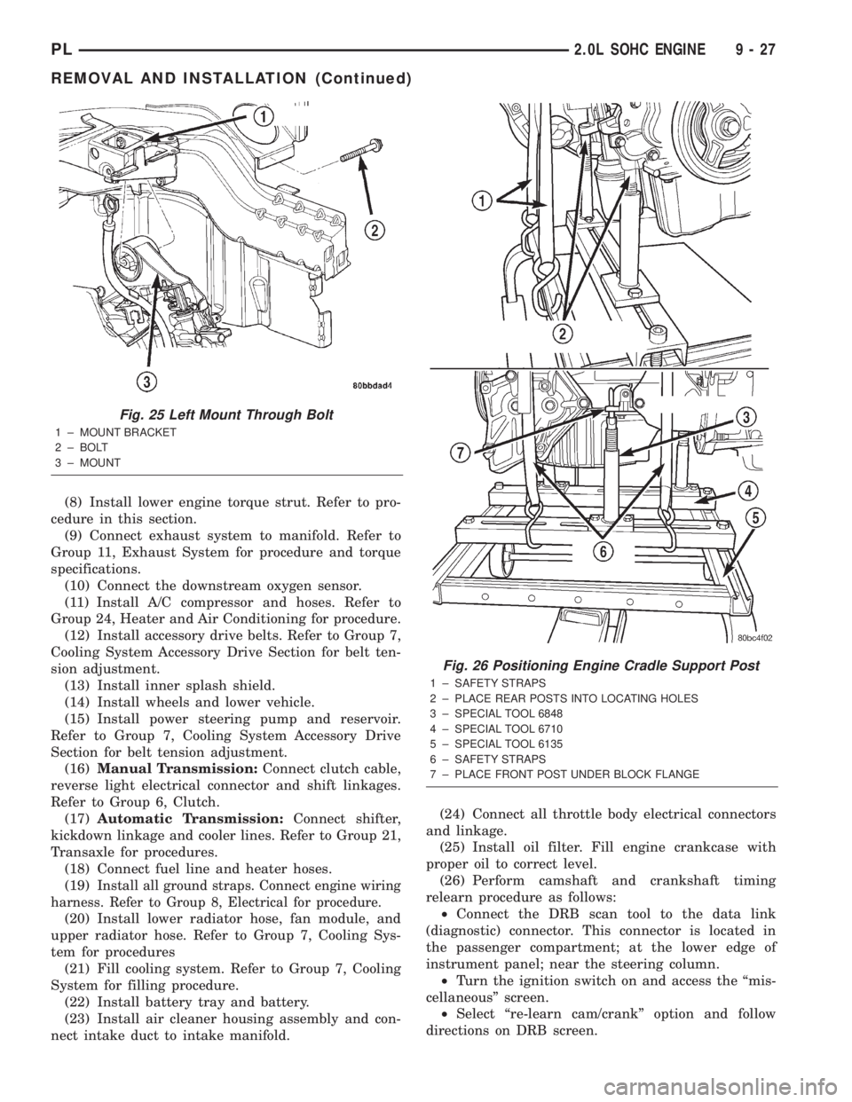
posts (Fig. 26). Tighten mounts to cradle frame. This
will keep support posts from moving when removing
or installing engine and transmission.
(30) Install safety straps around the engine to cra-
dle (Fig. 26). Tighten straps and lock them into posi-
tion.
WARNING: Safety straps MUST be used.(31) Raise vehicle enough to see if straps are tight
enough to hold cradle assembly to engine.
(32) Lower vehicle so weight of the engine and
transmission ONLY is on the cradle assembly.
(33) Remove the upper engine torque strut.
(34) Remove right and left engine and transaxle
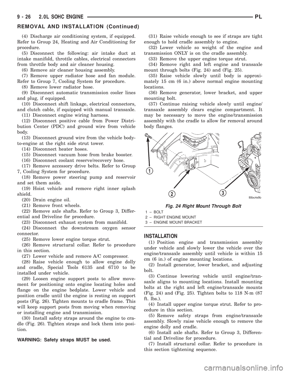
mount through bolts (Fig. 24) and (Fig. 25).
(35) Raise vehicle slowly until body is approxi-
mately 15 cm (6 in.) above normal engine mounting
locations.
(36) Remove generator, lower bracket, and upper
mounting bolt.
(37) Continue raising vehicle slowly until engine/
transaxle assembly clears engine compartment. It
may be necessary to move the engine/transmission
assembly with the cradle to allow for removal around
body flanges.
INSTALLATION
(1) Position engine and transmission assembly
under vehicle and slowly lower the vehicle over the
engine/transaxle assembly until vehicle is within 15
cm (6 in.) of engine mounting locations.
(2) Install generator, lower bracket, and adjusting
bolt.
(3) Continue lowering vehicle until engine/tran-
saxle aligns to mounting locations. Install mounting
bolts at the right and left engine/transaxle mounts
(Fig. 24) and (Fig. 25). Tighten bolts to 118 N´m (87
ft. lbs.).
(4) Install upper engine torque strut. Refer to pro-
cedure in this section.
(5) Remove safety straps from engine/transaxle
assembly. Slowly raise vehicle enough to remove the
engine dolly and cradle.
(6) Install axle shafts. Refer to Group 3, Differen-
tial and Driveline for procedure.
(7) Install structural collar. Refer to procedure in
this section tightening sequence.
Fig. 24 Right Mount Through Bolt
1 ± BOLT
2 ± RIGHT ENGINE MOUNT
3 ± ENGINE MOUNT BRACKET
9 - 26 2.0L SOHC ENGINEPL
REMOVAL AND INSTALLATION (Continued)
Page 750 of 1285
(8) Install lower engine torque strut. Refer to pro-
cedure in this section.
(9) Connect exhaust system to manifold. Refer to
Group 11, Exhaust System for procedure and torque
specifications.
(10) Connect the downstream oxygen sensor.
(11) Install A/C compressor and hoses. Refer to
Group 24, Heater and Air Conditioning for procedure.
(12) Install accessory drive belts. Refer to Group 7,
Cooling System Accessory Drive Section for belt ten-
sion adjustment.
(13) Install inner splash shield.
(14) Install wheels and lower vehicle.
(15) Install power steering pump and reservoir.
Refer to Group 7, Cooling System Accessory Drive
Section for belt tension adjustment.
(16)Manual Transmission:Connect clutch cable,
reverse light electrical connector and shift linkages.
Refer to Group 6, Clutch.
(17)Automatic Transmission:Connect shifter,
kickdown linkage and cooler lines. Refer to Group 21,
Transaxle for procedures.
(18) Connect fuel line and heater hoses.
(19)
Install all ground straps. Connect engine wiring
harness. Refer to Group 8, Electrical for procedure.
(20) Install lower radiator hose, fan module, and
upper radiator hose. Refer to Group 7, Cooling Sys-
tem for procedures
(21) Fill cooling system. Refer to Group 7, Cooling
System for filling procedure.
(22) Install battery tray and battery.
(23) Install air cleaner housing assembly and con-
nect intake duct to intake manifold.(24) Connect all throttle body electrical connectors
and linkage.
(25) Install oil filter. Fill engine crankcase with
proper oil to correct level.
(26) Perform camshaft and crankshaft timing
relearn procedure as follows:
²Connect the DRB scan tool to the data link
(diagnostic) connector. This connector is located in
the passenger compartment; at the lower edge of
instrument panel; near the steering column.
²Turn the ignition switch on and access the ªmis-
cellaneousº screen.
²Select ªre-learn cam/crankº option and follow
directions on DRB screen.
Fig. 25 Left Mount Through Bolt
1 ± MOUNT BRACKET
2 ± BOLT
3 ± MOUNT
Fig. 26 Positioning Engine Cradle Support Post
1 ± SAFETY STRAPS
2 ± PLACE REAR POSTS INTO LOCATING HOLES
3 ± SPECIAL TOOL 6848
4 ± SPECIAL TOOL 6710
5 ± SPECIAL TOOL 6135
6 ± SAFETY STRAPS
7 ± PLACE FRONT POST UNDER BLOCK FLANGE
PL2.0L SOHC ENGINE 9 - 27
REMOVAL AND INSTALLATION (Continued)
Page 858 of 1285
position of the throttle blade changes, the resistance
of the TPS changes.
OPERATION
The PCM supplies approximately 5 volts DC to the
TPS. The TPS output voltage (input signal to the
powertrain control module) represents throttle blade
position. The TPS output voltage to the PCM varies
from approximately 0.35 to 1.03 volts at minimum
throttle opening (idle) to a maximum of 3.1 to 4.0
volts at wide open throttle.
Along with inputs from other sensors, the PCM
uses the TPS input to determine current engine oper-
ating conditions. The PCM also adjusts fuel injector
pulse width and ignition timing based on these
inputs.
When the TPS indicates a voltage that is too high,
too low or not believable, the PCM sets a DTC. When
the DTC is set, the MIL is illuminated and the PCM
moves into limp-in mode. Limp-in for the TPS is
divided into three categories:
²Idle
²Part-throttle
²Wide open throttle (WOT)
VEHICLE SPEED SIGNAL (VSS)ÐPCM INPUT
DESCRIPTION
The PCM requires the VSS to be able to control
the following programs:
²Speed Control
²IAC motor (during deceleration)
²Injection pulse width (during deceleration)
²OBD II diagnostics
²PCM mileage EEPROM
²Road speed shutdown
²Speedometer/Odometer (bused message)NOTE: Road Speed Shutdown is the PCM shutting
off fuel injectors above a preset vehicle speed.
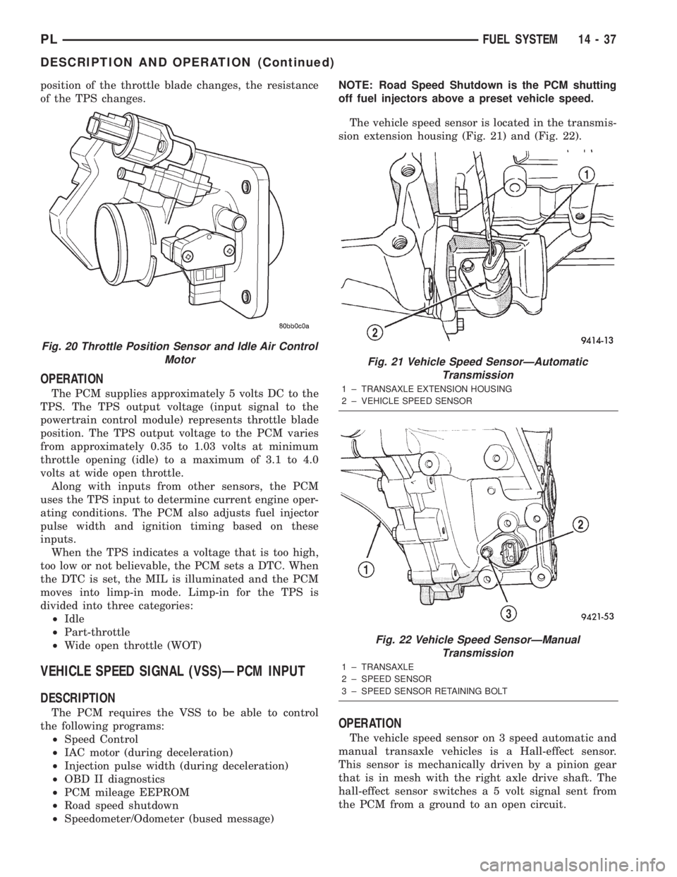
The vehicle speed sensor is located in the transmis-
sion extension housing (Fig. 21) and (Fig. 22).
OPERATION
The vehicle speed sensor on 3 speed automatic and
manual transaxle vehicles is a Hall-effect sensor.
This sensor is mechanically driven by a pinion gear
that is in mesh with the right axle drive shaft. The
hall-effect sensor switches a 5 volt signal sent from
the PCM from a ground to an open circuit.
Fig. 20 Throttle Position Sensor and Idle Air Control
Motor
Fig. 21 Vehicle Speed SensorÐAutomatic
Transmission
1 ± TRANSAXLE EXTENSION HOUSING
2 ± VEHICLE SPEED SENSOR
Fig. 22 Vehicle Speed SensorÐManual
Transmission
1 ± TRANSAXLE
2 ± SPEED SENSOR
3 ± SPEED SENSOR RETAINING BOLT
PLFUEL SYSTEM 14 - 37
DESCRIPTION AND OPERATION (Continued)
Page 888 of 1285
reduces the power required to drive the pump and
holds down temperature build-up.
When steering conditions exceed maximum pres-
sure requirements, such as when the wheels are
turned against the stops, the pressure built up in the
steering gear exerts pressure on the spring end of the
flow control valve. The high pressure lifts the relief
valve ball from its seat and allows oil to flow through
a trigger orifice located in the outlet fitting. This
reduces pressure on the spring end of the flow con-
trol valve which then opens and allows the oil to
return to the intake side of the pump. This action
limits maximum pressure output of the pump to a
safe level.
Under normal power steering pump operating con-
ditions, pressure requirements of the pump are below
maximum, causing the pressure relief valve to
remain closed.
POWER STEERING FLUID RESERVOIR
The power steering fluid reservoir is mounted on
the power steering pump using 3 bolts (Fig. 1). It
stores fluid for the power steering system.
The power steering fluid reservoir is considered an
integral part of the power steering pump and is not
serviced separately.
SERVICE PROCEDURES
POWER STEERING PUMP INITIAL OPERATION
CAUTION: The fluid level should be checked with
engine off to prevent injury from moving compo-
nents. Use only MoparTPower Steering Fluid. Do
not use automatic transmission fluid. Do not over-
fill.
Wipe the filler cap clean, then check the fluid level.
The dipstick should indicateCOLDwhen the fluid is
at normal temperature, approximately 21ÉC to 27ÉC
(70ÉF to 80ÉF).
(1) Fill the power steering fluid reservoir to the
proper level and let the fluid settle for at least two
minutes.
(2) Start the engine and let run for a few seconds,
then turn the engine off.
(3) Add fluid if necessary. Repeat the above proce-
dure until the fluid level remains constant after run-
ning the engine.
(4) Raise the front wheels off the ground.
(5) Start the engine. Slowly turn the steering
wheel right and left, lightly contacting the wheel
stops.
(6) Add power steering fluid if necessary.
(7) Lower the vehicle and turn the steering wheel
slowly from lock to lock.(8) Stop the engine. Check the fluid level and refill
as required.
(9) If the fluid is extremely foamy, allow the vehi-
cle to stand a few minutes and repeat the above pro-
cedure.
REMOVAL AND INSTALLATION
SERVICE WARNINGS AND CAUTIONS
WARNING: POWER STEERING FLUID, ENGINE
PARTS AND EXHAUST SYSTEM MAY BE
EXTREMELY HOT IF ENGINE HAS BEEN RUNNING.
DO NOT START ENGINE WITH ANY LOOSE OR DIS-
CONNECTED HOSES. DO NOT ALLOW HOSES TO
TOUCH HOT EXHAUST MANIFOLD OR CATALYST.
WARNING: FLUID LEVEL SHOULD BE CHECKED
WITH THE ENGINE OFF TO PREVENT PERSONAL
INJURY FROM MOVING PARTS.
CAUTION: When the system is open, cap all open
ends of the hoses, power steering pump fittings or
power steering gear ports to prevent entry of for-
eign material into the components.
NOTE: Do not use any type of automatic transmis-
sion fluid in the power steering system.
POWER STEERING PUMP
NOTE: Before proceeding with this removal and
installation procedure, review SERVICE WARNINGS
AND CAUTIONS at the beginning of REMOVAL AND
INSTALLATION in this section.
REMOVAL
(1) Remove battery cable from the negative post on
the battery.
(2) Siphon as much fluid as possible from the
power steering fluid reservoir.
(3) Remove the power steering pump drive belt
from the power steering pump pulley. Refer to
ACCESSORY DRIVE BELTS in the COOLING SYS-
TEM service manual group for the required removal
and installation procedure.
(4) Remove the hose clamp securing the return
hose to the power steering fluid reservoir. Slide the
hose off the end of the reservoir fitting. (Fig. 2).
(5) Back out the tube nut securing the power
steering fluid pressure hose to the power steering
pump and remove the hose from the pump (Fig. 2).
PLSTEERING 19 - 17
DESCRIPTION AND OPERATION (Continued)