2000 DODGE NEON manual transmission
[x] Cancel search: manual transmissionPage 911 of 1285
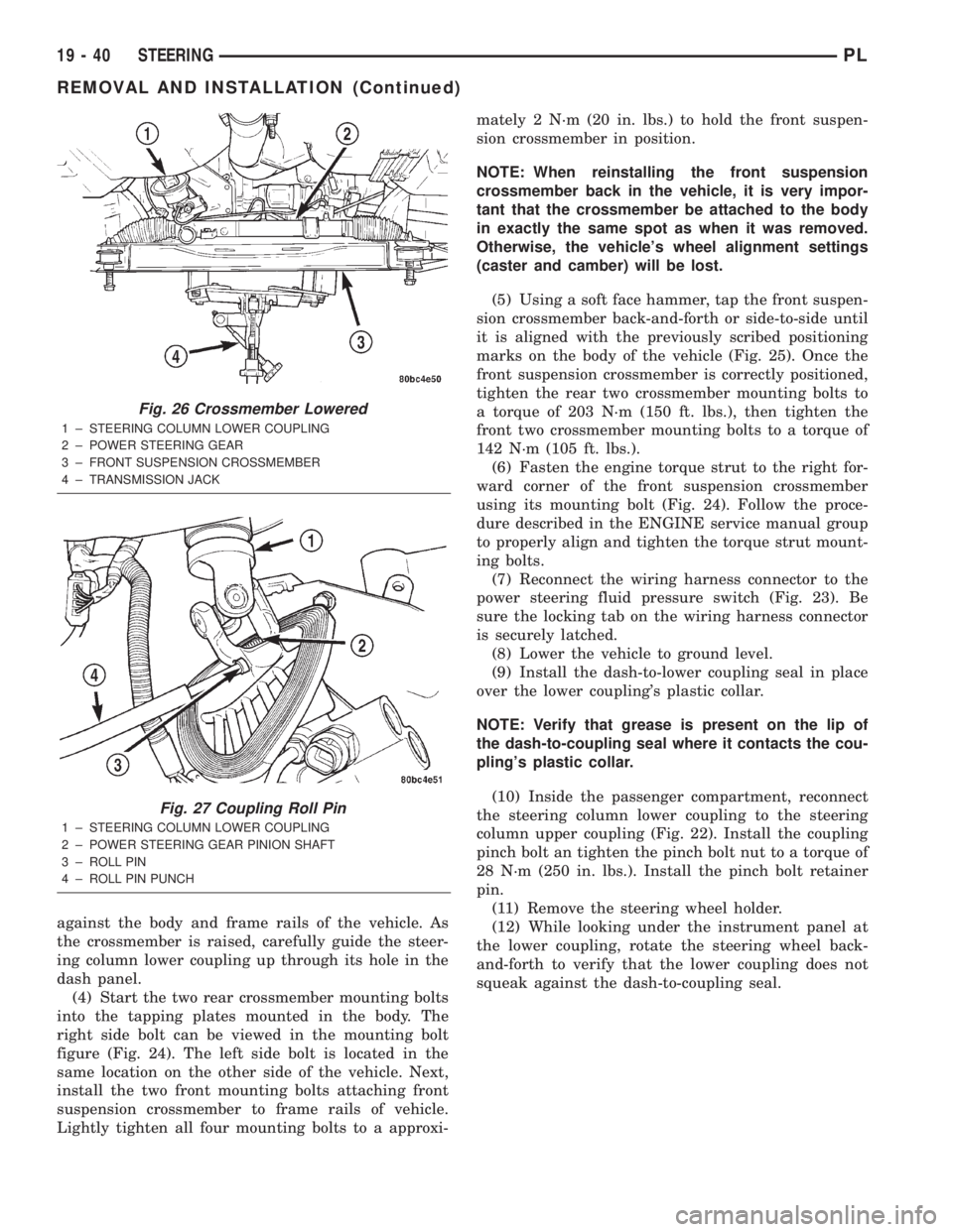
against the body and frame rails of the vehicle. As
the crossmember is raised, carefully guide the steer-
ing column lower coupling up through its hole in the
dash panel.
(4) Start the two rear crossmember mounting bolts
into the tapping plates mounted in the body. The
right side bolt can be viewed in the mounting bolt
figure (Fig. 24). The left side bolt is located in the
same location on the other side of the vehicle. Next,
install the two front mounting bolts attaching front
suspension crossmember to frame rails of vehicle.
Lightly tighten all four mounting bolts to a approxi-mately 2 N´m (20 in. lbs.) to hold the front suspen-
sion crossmember in position.
NOTE: When reinstalling the front suspension
crossmember back in the vehicle, it is very impor-
tant that the crossmember be attached to the body
in exactly the same spot as when it was removed.
Otherwise, the vehicle's wheel alignment settings
(caster and camber) will be lost.
(5) Using a soft face hammer, tap the front suspen-
sion crossmember back-and-forth or side-to-side until
it is aligned with the previously scribed positioning
marks on the body of the vehicle (Fig. 25). Once the
front suspension crossmember is correctly positioned,
tighten the rear two crossmember mounting bolts to
a torque of 203 N´m (150 ft. lbs.), then tighten the
front two crossmember mounting bolts to a torque of
142 N´m (105 ft. lbs.).
(6) Fasten the engine torque strut to the right for-
ward corner of the front suspension crossmember
using its mounting bolt (Fig. 24). Follow the proce-
dure described in the ENGINE service manual group
to properly align and tighten the torque strut mount-
ing bolts.
(7) Reconnect the wiring harness connector to the
power steering fluid pressure switch (Fig. 23). Be
sure the locking tab on the wiring harness connector
is securely latched.
(8) Lower the vehicle to ground level.
(9) Install the dash-to-lower coupling seal in place
over the lower coupling's plastic collar.
NOTE: Verify that grease is present on the lip of
the dash-to-coupling seal where it contacts the cou-
pling's plastic collar.
(10) Inside the passenger compartment, reconnect
the steering column lower coupling to the steering
column upper coupling (Fig. 22). Install the coupling
pinch bolt an tighten the pinch bolt nut to a torque of
28 N´m (250 in. lbs.). Install the pinch bolt retainer
pin.
(11) Remove the steering wheel holder.
(12) While looking under the instrument panel at
the lower coupling, rotate the steering wheel back-
and-forth to verify that the lower coupling does not
squeak against the dash-to-coupling seal.
Fig. 26 Crossmember Lowered
1 ± STEERING COLUMN LOWER COUPLING
2 ± POWER STEERING GEAR
3 ± FRONT SUSPENSION CROSSMEMBER
4 ± TRANSMISSION JACK
Fig. 27 Coupling Roll Pin
1 ± STEERING COLUMN LOWER COUPLING
2 ± POWER STEERING GEAR PINION SHAFT
3 ± ROLL PIN
4 ± ROLL PIN PUNCH
19 - 40 STEERINGPL
REMOVAL AND INSTALLATION (Continued)
Page 915 of 1285
ferential case transfers torque from the ring gear to the
drive axles by means of differential side gears.
The NV T350 (A-578) transaxle internal components
can only be serviced by separating the case halves.
CAUTION: The transaxle output shaft is serviced as
a unit. No disassembly and reassembly is possible.
Damage to the transaxle may result.
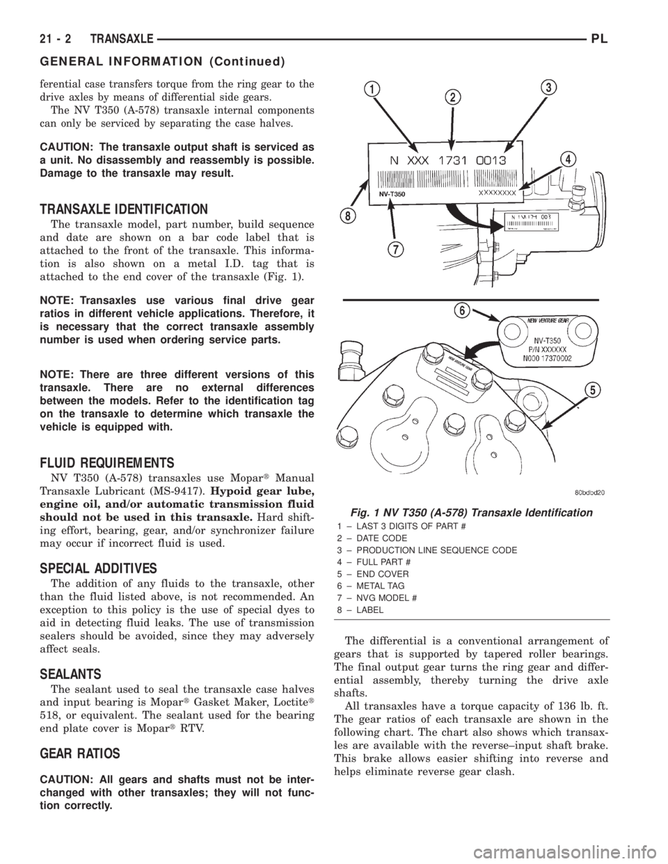
TRANSAXLE IDENTIFICATION
The transaxle model, part number, build sequence
and date are shown on a bar code label that is
attached to the front of the transaxle. This informa-
tion is also shown on a metal I.D. tag that is
attached to the end cover of the transaxle (Fig. 1).
NOTE: Transaxles use various final drive gear
ratios in different vehicle applications. Therefore, it
is necessary that the correct transaxle assembly
number is used when ordering service parts.
NOTE: There are three different versions of this
transaxle. There are no external differences
between the models. Refer to the identification tag
on the transaxle to determine which transaxle the
vehicle is equipped with.
FLUID REQUIREMENTS
NV T350 (A-578) transaxles use MopartManual
Transaxle Lubricant (MS-9417).Hypoid gear lube,
engine oil, and/or automatic transmission fluid
should not be used in this transaxle.Hard shift-
ing effort, bearing, gear, and/or synchronizer failure
may occur if incorrect fluid is used.
SPECIAL ADDITIVES
The addition of any fluids to the transaxle, other
than the fluid listed above, is not recommended. An
exception to this policy is the use of special dyes to
aid in detecting fluid leaks. The use of transmission
sealers should be avoided, since they may adversely
affect seals.
SEALANTS
The sealant used to seal the transaxle case halves
and input bearing is MopartGasket Maker, Loctitet
518, or equivalent. The sealant used for the bearing
end plate cover is MopartRTV.
GEAR RATIOS
CAUTION: All gears and shafts must not be inter-
changed with other transaxles; they will not func-
tion correctly.The differential is a conventional arrangement of
gears that is supported by tapered roller bearings.
The final output gear turns the ring gear and differ-
ential assembly, thereby turning the drive axle
shafts.
All transaxles have a torque capacity of 136 lb. ft.
The gear ratios of each transaxle are shown in the
following chart. The chart also shows which transax-
les are available with the reverse±input shaft brake.
This brake allows easier shifting into reverse and
helps eliminate reverse gear clash.
Fig. 1 NV T350 (A-578) Transaxle Identification
1 ± LAST 3 DIGITS OF PART #
2 ± DATE CODE
3 ± PRODUCTION LINE SEQUENCE CODE
4 ± FULL PART #
5 ± END COVER
6 ± METAL TAG
7 ± NVG MODEL #
8 ± LABEL
21 - 2 TRANSAXLEPL
GENERAL INFORMATION (Continued)
Page 969 of 1285
FLUID LEVEL AND CONDITION
NOTE: The transmission and differential sump have
a common oil sump with a communicating opening
between the two.
The torque converter fills in both the P (Park) and
N (Neutral) positions. Place the selector lever in P
(Park) to be sure that the fluid level check is accu-
rate.The engine should be running at idle
speed for at least one minute, with the vehicle
on level ground. This will ensure complete oil
level stabilization between differential and
transmission.The fluid should be at normal operat-
ing temperature (approximately 82É C. or 180É F.).
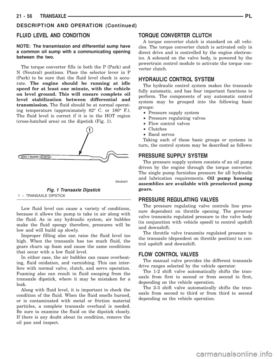
The fluid level is correct if it is in the HOT region
(cross-hatched area) on the dipstick (Fig. 1).
Low fluid level can cause a variety of conditions,
because it allows the pump to take in air along with
the fluid. As in any hydraulic system, air bubbles
make the fluid spongy therefore, pressures will be
low and will build up slowly.
Improper filling also can raise the fluid level too
high. When the transaxle has too much fluid, the
gears churn up foam and cause the same conditions
that occur with a low fluid level.
In either case, the air bubbles can cause overheat-
ing, fluid oxidation, and varnishing. This can inter-
fere with normal valve, clutch, and servo operation.
Foaming also can result in fluid escaping from the
transaxle dipstick, where it may be mistaken for a
leak.
Along with fluid level, it is important to check the
condition of the fluid. When the fluid smells burned,
or is contaminated with metal or friction material
particles, a complete transaxle overhaul is needed.
Be sure to examine the fluid on the dipstick closely.
If there is any doubt about its condition, remove the
oil pan and inspect.
TORQUE CONVERTER CLUTCH
A torque converter clutch is standard on all vehi-
cles. The torque converter clutch is activated only in
direct drive and is controlled by the engine electron-
ics. A solenoid on the valve body, is powered by the
powertrain control module to activate the torque con-
verter clutch.
HYDRAULIC CONTROL SYSTEM
The hydraulic control system makes the transaxle
fully automatic, and has four important functions to
perform. The components of any automatic control
system may be grouped into the following basic
groups:
²Pressure supply system
²Pressure regulating valves
²Flow control valves
²Clutches
²Band servos
Taking each of these basic groups or systems in
turn, the control system may be described as follows:
PRESSURE SUPPLY SYSTEM
The pressure supply system consists of an oil pump
driven by the engine through the torque converter.
The single pump furnishes pressure for all hydraulic
and lubrication requirements.Oil pump housing
assemblies are available with preselected pump
gears.
PRESSURE REGULATING VALVES
The pressure regulating valve controls line pres-
sure dependent on throttle opening. The governor
valve transmits regulated pressure to the valve body
(in conjunction with vehicle speed) to control upshift
and downshift.
The throttle valve transmits regulated pressure to
the transaxle (dependent on throttle position) to con-
trol upshift and downshift.
FLOW CONTROL VALVES
The manual valve provides the different transaxle
drive ranges selected by the vehicle operator.
The 1-2 shift valve automatically shifts the tran-
saxle from first to second or from second to first,
depending on the vehicle operation.
The 2-3 shift valve automatically shifts the tran-
saxle from second to third or from third to second
depending on the vehicle operation.
Fig. 1 Transaxle Dipstick
1 ± TRANSAXLE DIPSTICK
21 - 56 TRANSAXLEPL
DESCRIPTION AND OPERATION (Continued)
Page 972 of 1285
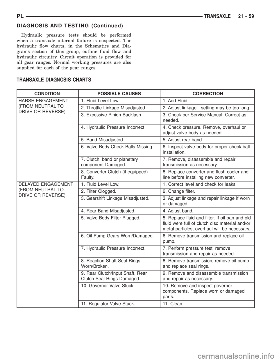
Hydraulic pressure tests should be performed
when a transaxle internal failure is suspected. The
hydraulic flow charts, in the Schematics and Dia-
grams section of this group, outline fluid flow and
hydraulic circuitry. Circuit operation is provided for
all gear ranges. Normal working pressures are also
supplied for each of the gear ranges.
TRANSAXLE DIAGNOSIS CHARTS
CONDITION POSSIBLE CAUSES CORRECTION
HARSH ENGAGEMENT
(FROM NEUTRAL TO
DRIVE OR REVERSE)1. Fluid Level Low 1. Add Fluid
2. Throttle Linkage Misadjusted 2. Adjust linkage - setting may be too long.
3. Excessive Pinion Backlash 3. Check per Service Manual. Correct as
needed.
4. Hydraulic Pressure Incorrect 4. Check pressure. Remove, overhaul or
adjust valve body as needed.
5. Band Misadjusted. 5. Adjust rear band.
6. Valve Body Check Balls Missing. 6. Inspect valve body for proper check ball
installation.
7. Clutch, band or planetary
component Damaged.7. Remove, disassemble and repair
transmission as necessary.
8. Converter Clutch (if equipped)
Faulty.8. Replace converter and flush cooler and
line before installing new converter.
DELAYED ENGAGEMENT
(FROM NEUTRAL TO
DRIVE OR REVERSE)1. Fluid Level Low. 1. Correct level and check for leaks.
2. Filter Clogged. 2. Change filter.
3. Gearshift Linkage Misadjusted. 3. Adjust linkage and repair linkage if worn
or damaged.
4. Rear Band Misadjusted. 4. Adjust band.
5. Valve Body Filter Plugged. 5. Replace fluid and filter. If oil pan and old
fluid were full of clutch disc material and/or
metal particles, overhaul will be necessary.
6. Oil Pump Gears Worn/Damaged. 6. Remove transmission and replace oil
pump.
7. Hydraulic Pressure Incorrect. 7. Perform pressure test, remove
transmission and repair as needed.
8. Reaction Shaft Seal Rings
Worn/Broken.8. Remove transmission, remove oil pump
and replace seal rings.
9. Rear Clutch/Input Shaft, Rear
Clutch Seal Rings Damaged.9. Remove and disassemble transmission
and repair as necessary.
10. Governor Valve Stuck. 10. Remove and inspect governor
components. Replace worn or damaged
parts.
11. Regulator Valve Stuck. 11. Clean.
PLTRANSAXLE 21 - 59
DIAGNOSIS AND TESTING (Continued)
Page 983 of 1285
LOW AND REVERSE SERVO (REAR)
Direct air pressure into LOW/REVERSE SERVO
APPLY passage. Operation of servo is indicated by a
tightening of rear band. Spring tension on servo pis-
ton should release the band.
If clutches and servos operate properly, no upshift
indicates that a malfunction exists in the valve body.
FLUID LEAKAGE-TRANSAXLE TORQUE
CONVERTER HOUSING AREA
(1) Check for source of leakage.
(2) Since fluid leakage near the torque converter
area may be from an engine oil leak, the area should
be checked closely. Factory fill fluid is dyed red and,
therefore, can be distinguished from engine oil.
(3) Prior to removing the transaxle, perform the
following checks:
(4) When leakage is determined to originate from
the transaxle, check fluid level prior to removal of
the transaxle and torque converter.
(5) High oil level can result in oil leakage out the
vent in the dipstick. If the fluid level is high, adjust
to proper level.
(6) After performing this operation, inspect for
leakage. If a leak persists, perform the following
operation on the vehicle. This will determine if the
torque converter or transaxle is leaking.
TORQUE CONVERTER LEAKAGE
Possible sources of torque converter leakage are:
²Torque converter weld leaks at the outside diam-
eter (peripheral) weld
²Torque converter hub weld
²Torque converter impeller shell cracked adjacent
to hub
²At drive lug welds
NOTE: Hub weld is inside and not visible. Do not
attempt to repair. Replace torque converter.
BRAKE TRANSMISSION SHIFT INTERLOCK
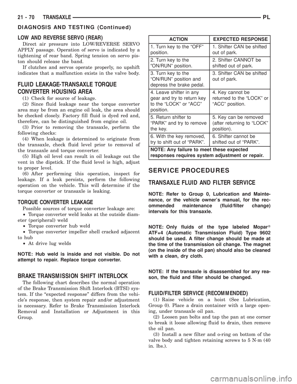
The following chart describes the normal operation
of the Brake Transmission Shift Interlock (BTSI) sys-
tem. If the ªexpected responseº differs from the vehi-
cle's response, then system repair and/or adjustment
is necessary. Refer to Brake Transmission Interlock
Removal and Installation or Adjustment in this
Group.
SERVICE PROCEDURES
TRANSAXLE FLUID AND FILTER SERVICE
NOTE: Refer to Group 0, Lubrication and Mainte-
nance, or the vehicle owner's manual, for the rec-
ommended maintenance (fluid/filter change)
intervals for this transaxle.
NOTE: Only fluids of the type labeled MoparT
ATF+4 (Automatic Transmission Fluid) Type 9602
should be used. A filter change should be made at
the time of the transmission oil change. The magnet
(on the inside of the oil pan) should also be cleaned
with a clean, dry cloth.
NOTE: If the transaxle is disassembled for any rea-
son, the fluid and filter should be changed.
FLUID/FILTER SERVICE (RECOMMENDED)
(1) Raise vehicle on a hoist (See Lubrication,
Group 0). Place a drain container with a large open-
ing, under transaxle oil pan.
(2) Loosen pan bolts and tap the pan at one corner
to break it loose allowing fluid to drain, then remove
the oil pan.
(3) Install a new filter and o-ring on bottom of the
valve body and tighten retaining screws to 5 N´m (40
in. lbs.).
ACTION EXPECTED RESPONSE
1. Turn key to the ªOFFº
position.1. Shifter CAN be shifted
out of park.
2. Turn key to the
9ON/RUNº position.2. Shifter CANNOT be
shifted out of park.
3. Turn key to the
ªON/RUNº position and
depress the brake pedal.3. Shifter CAN be shifted
out of park.
4. Leave shifter in any
gear and try to return key
to the ªLOCKº or9ACCº
position.4. Key cannot be
returned to the ªLOCKº or
ªACCº position.
5. Return shifter to
ªPARKº and try to remove
the key.5. Key can be removed
(after returning to ªLOCKº
position).
6. With the key removed,
try to shift out of ªPARKº.6. Shifter cannot be
shifted out of ªPARKº.
NOTE: Any failure to meet these expected
responses requires system adjustment or repair.
21 - 70 TRANSAXLEPL
DIAGNOSIS AND TESTING (Continued)
Page 1063 of 1285
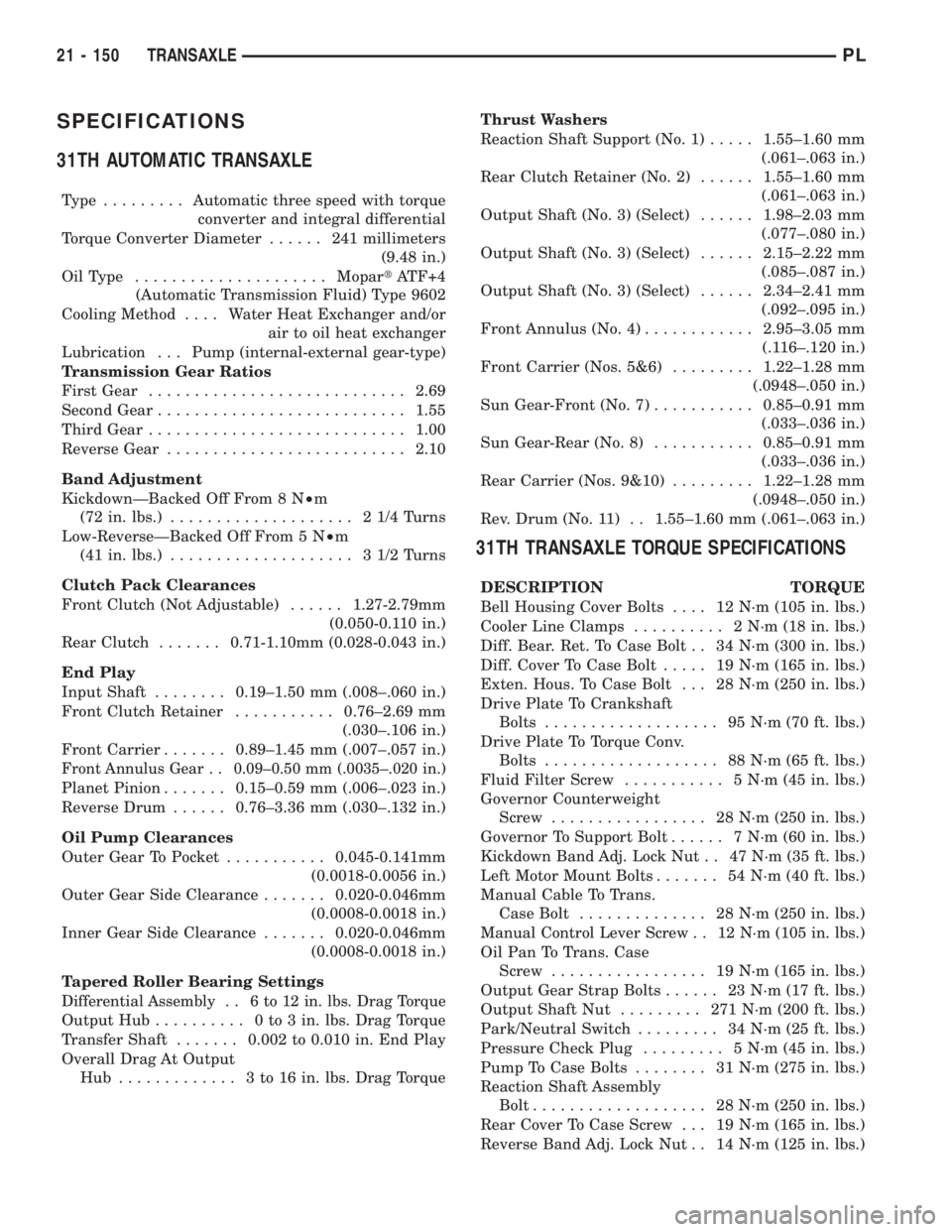
SPECIFICATIONS
31TH AUTOMATIC TRANSAXLE
Type .........Automatic three speed with torque
converter and integral differential
Torque Converter Diameter...... 241millimeters
(9.48 in.)
OilType .....................MopartATF+4
(Automatic Transmission Fluid) Type 9602
Cooling Method.... Water Heat Exchanger and/or
air to oil heat exchanger
Lubrication . . . Pump (internal-external gear-type)
Transmission Gear Ratios
First Gear............................2.69
Second Gear...........................1.55
Third Gear............................1.00
Reverse Gear..........................2.10
Band Adjustment
KickdownÐBacked Off From 8 N²m
(72 in. lbs.).................... 21/4Turns
Low-ReverseÐBacked Off From 5 N²m
(41 in. lbs.).................... 31/2Turns
Clutch Pack Clearances
Front Clutch (Not Adjustable)......1.27-2.79mm
(0.050-0.110 in.)
Rear Clutch.......0.71-1.10mm (0.028-0.043 in.)
End Play
Input Shaft........0.19±1.50 mm (.008±.060 in.)
Front Clutch Retainer...........0.76±2.69 mm
(.030±.106 in.)
Front Carrier.......0.89±1.45 mm (.007±.057 in.)
Front Annulus Gear . . 0.09±0.50 mm (.0035±.020 in.)
Planet Pinion.......0.15±0.59 mm (.006±.023 in.)
Reverse Drum......0.76±3.36 mm (.030±.132 in.)
Oil Pump Clearances
Outer Gear To Pocket...........0.045-0.141mm
(0.0018-0.0056 in.)
Outer Gear Side Clearance.......0.020-0.046mm
(0.0008-0.0018 in.)
Inner Gear Side Clearance.......0.020-0.046mm
(0.0008-0.0018 in.)
Tapered Roller Bearing Settings
Differential Assembly . . 6 to 12 in. lbs. Drag Torque
Output Hub.......... 0to3in.lbs. Drag Torque
Transfer Shaft.......0.002 to 0.010 in. End Play
Overall Drag At Output
Hub ............. 3to16in.lbs. Drag TorqueThrust Washers
Reaction Shaft Support (No. 1).....1.55±1.60 mm
(.061±.063 in.)
Rear Clutch Retainer (No. 2)......1.55±1.60 mm
(.061±.063 in.)
Output Shaft (No. 3) (Select)......1.98±2.03 mm
(.077±.080 in.)
Output Shaft (No. 3) (Select)......2.15±2.22 mm
(.085±.087 in.)
Output Shaft (No. 3) (Select)......2.34±2.41 mm
(.092±.095 in.)
Front Annulus (No. 4)............2.95±3.05 mm
(.116±.120 in.)
Front Carrier (Nos. 5&6).........1.22±1.28 mm
(.0948±.050 in.)
Sun Gear-Front (No. 7)...........0.85±0.91 mm
(.033±.036 in.)
Sun Gear-Rear (No. 8)...........0.85±0.91 mm
(.033±.036 in.)
Rear Carrier (Nos. 9&10).........1.22±1.28 mm
(.0948±.050 in.)
Rev. Drum (No. 11) . . 1.55±1.60 mm (.061±.063 in.)
31TH TRANSAXLE TORQUE SPECIFICATIONS
DESCRIPTION TORQUE
Bell Housing Cover Bolts.... 12N´m(105 in. lbs.)
Cooler Line Clamps.......... 2N´m(18in.lbs.)
Diff. Bear. Ret. To Case Bolt . . 34 N´m (300 in. lbs.)
Diff. Cover To Case Bolt..... 19N´m(165 in. lbs.)
Exten. Hous. To Case Bolt . . . 28 N´m (250 in. lbs.)
Drive Plate To Crankshaft
Bolts................... 95N´m(70ft.lbs.)
Drive Plate To Torque Conv.
Bolts................... 88N´m(65ft.lbs.)
Fluid Filter Screw........... 5N´m(45in.lbs.)
Governor Counterweight
Screw................. 28N´m(250 in. lbs.)
Governor To Support Bolt...... 7N´m(60in.lbs.)
Kickdown Band Adj. Lock Nut . . 47 N´m (35 ft. lbs.)
Left Motor Mount Bolts....... 54N´m(40ft.lbs.)
Manual Cable To Trans.
Case Bolt.............. 28N´m(250 in. lbs.)
Manual Control Lever Screw . . 12 N´m (105 in. lbs.)
Oil Pan To Trans. Case
Screw................. 19N´m(165 in. lbs.)
Output Gear Strap Bolts...... 23N´m(17ft.lbs.)
Output Shaft Nut......... 271N´m(200 ft. lbs.)
Park/Neutral Switch......... 34N´m(25ft.lbs.)
Pressure Check Plug......... 5N´m(45in.lbs.)
Pump To Case Bolts........ 31N´m(275 in. lbs.)
Reaction Shaft Assembly
Bolt................... 28N´m(250 in. lbs.)
Rear Cover To Case Screw . . . 19 N´m (165 in. lbs.)
Reverse Band Adj. Lock Nut . . 14 N´m (125 in. lbs.)
21 - 150 TRANSAXLEPL
Page 1171 of 1285
(3) Disengage clips attaching trim to lower quarter
panel.
(4) Remove seat belt from slot in trim panel.
(5) Remove lower quarter trim from vehicle (Fig.
66).
INSTALLATION
(1) Position lower quarter trim panel to vehicle.
(2) Install seat belt to slot in trim panel.
(3) Align locating pins on backside of trim panel to
mating holes in inner quarter panel.
(4) Press clips on trim panel into slots in inner
quarter panel.
(5) Install rear seat back and cushion.
(6) Install upper quarter trim panel.
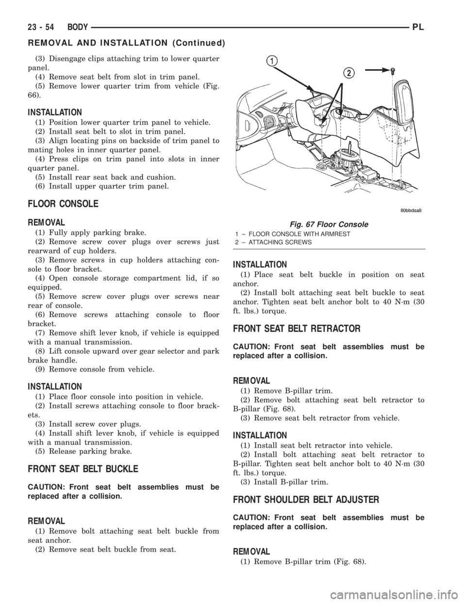
FLOOR CONSOLE
REMOVAL
(1) Fully apply parking brake.
(2) Remove screw cover plugs over screws just
rearward of cup holders.
(3) Remove screws in cup holders attaching con-
sole to floor bracket.
(4) Open console storage compartment lid, if so
equipped.
(5) Remove screw cover plugs over screws near
rear of console.
(6) Remove screws attaching console to floor
bracket.
(7) Remove shift lever knob, if vehicle is equipped
with a manual transmission.
(8) Lift console upward over gear selector and park
brake handle.
(9) Remove console from vehicle.
INSTALLATION
(1) Place floor console into position in vehicle.
(2) Install screws attaching console to floor brack-
ets.
(3) Install screw cover plugs.
(4) Install shift lever knob, if vehicle is equipped
with a manual transmission.
(5) Release parking brake.
FRONT SEAT BELT BUCKLE
CAUTION: Front seat belt assemblies must be
replaced after a collision.
REMOVAL
(1) Remove bolt attaching seat belt buckle from
seat anchor.
(2) Remove seat belt buckle from seat.
INSTALLATION
(1) Place seat belt buckle in position on seat
anchor.
(2) Install bolt attaching seat belt buckle to seat
anchor. Tighten seat belt anchor bolt to 40 N´m (30
ft. lbs.) torque.
FRONT SEAT BELT RETRACTOR
CAUTION: Front seat belt assemblies must be
replaced after a collision.
REMOVAL
(1) Remove B-pillar trim.
(2) Remove bolt attaching seat belt retractor to
B-pillar (Fig. 68).
(3) Remove seat belt retractor from vehicle.
INSTALLATION
(1) Install seat belt retractor into vehicle.
(2) Install bolt attaching seat belt retractor to
B-pillar. Tighten seat belt anchor bolt to 40 N´m (30
ft. lbs.) torque.
(3) Install B-pillar trim.
FRONT SHOULDER BELT ADJUSTER
CAUTION: Front seat belt assemblies must be
replaced after a collision.
REMOVAL
(1) Remove B-pillar trim (Fig. 68).
Fig. 67 Floor Console
1 ± FLOOR CONSOLE WITH ARMREST
2 ± ATTACHING SCREWS
23 - 54 BODYPL
REMOVAL AND INSTALLATION (Continued)
Page 1283 of 1285
VIN DECODING INFORMATION
POSITION INTERPRETATION CODE = DESCRIPTION
1 Country of origin 1 = United States
2 Make C = Chrysler
3 Vehicle Type 3 = Passenger Car
4 Passenger Safety E = Active Restraints, Driver and Passenger Airbags
5 Car Line S = Neon BUX L. H. D.
V = Neon BUX R. H. D.
6 Series M = DD5 5-Speed Manual Transmission
A = 3-Speed Automatic Transmission
7 Body Style7 = 4 Door Pillared Hardtop
8 Engine C = 2.0L 4 Cyl. 16V SOHC
A = 1.8L 4 Cyl. 16V SOHC
9 Check Digit See explanation in this section.
10 Model Year Y = 2000
11 Assembly Plant D = Belvedere Assembly
12 Thru 17 Build Sequence 6 Digit number assigned by assembly plant
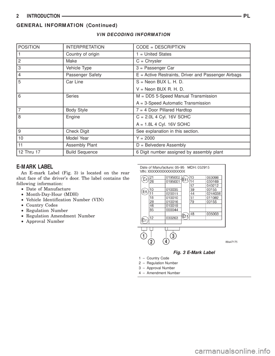
E-MARK LABEL
An E-mark Label (Fig. 3) is located on the rear
shut face of the driver's door. The label contains the
following information:
²Date of Manufacture
²Month-Day-Hour (MDH)
²Vehicle Identification Number (VIN)
²Country Codes
²Regulation Number
²Regulation Amendment Number
²Approval Number
Fig. 3 E-Mark Label
1 ± Country Code
2 ± Regulation Number
3 ± Approval Number
4 ± Amendment Number
2 INTRODUCTIONPL
GENERAL INFORMATION (Continued)