Page 17 of 96
111
15
General information and controls
Key positions
ONOperating position,
ignition and all electrical cir-
cuits switched on
R ° Ignition off,
steering lock released
(handlebar can be turned
freely to right or left)
d Warning:
Never turn the key to the R
position while riding. OFF°
Ignition off, steering lock
engaged
Turn the key to the R posi-
tion and press briefly
Turn the handlebar all the
way to the right and turn
the key to the OFF posi-
tion
Move the handlebar until
the steering lock engages
I° Parking light on,
steering lock engaged
\f Note:
Switch the parking light on only
for limited periods. Note state of
battery charge!
° The key can be removed in these
positions
Ignition switch and steering lock
�� �
Page 18 of 96
11
16
General information and controls
1Large, lockable stowage
compartment* with 12 V
power socket
2 Switch
C, hazard warning
flashers* (
b17)
* Optional extra
( ) Figure in brackets
bpage number for
description
3 Switch for heating package*
E = heatable grips
= handgrip and seat
heating
4 Switch
K for “headlight ” ON
Switch array
4132
�� �
Page 19 of 96
111
17
General information and controls
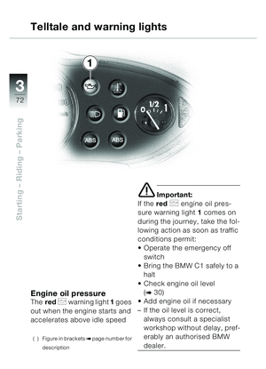
Hazard warning flashers*
\f Note:
The ignition must be switched
on before the hazard warning
flashers can be used.
Do not use the hazard warning
flashers for longer than abso-
lutely necessary.
Note state of battery charge.
Switching on the hazard
warning flashers:
Switch on the ignition
Operate hazard warning
flasher switch 1
– Hazard warning flashers in
operation
– Repeaters 2 and 3 for
left/right turn indicators in the
cluster flash (
b11)
Switch off the ignition
– The hazard warning flashers
continue to operate
Switching off the hazard
warning flashers:
Operate hazard warning
flasher switch 1
– Hazard warning flashers
cease to operate
– Telltale lights 2 and 3 for
left/right turn indicators in the
cluster OFF (
b11)
* Optional extra
( ) Figure in brackets
bpage number for
description
Hazard warning flashers*
32
1
�� �
Page 20 of 96
11
18
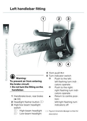
General information and controlsd Warning:
To prevent air from entering
the brake circuit:
• Do not turn the fitting on the
handlebar.
1 Handbrake lever, rear brake
(
b34)
2 Headlight flasher button
H
3High/low beam headlight
switch
FHigh-beam headlight
GLow-beam headlight 4
Horn push
z
5Turn indicator switch
YPush to the left:
left flashing turn indi-
cators operate
\bPush to the right:
right flashing turn indi-
cators operate
�Return to centre posi-
tion:
left/right flashing turn
indicators off
( ) Figure in bracketsbpage number for
description
Left handlebar fitting
3
4
21
5
�� �
Page 21 of 96
111
19
General information and controlsd Warning:
To prevent air from entering
the brake circuit:
Do not turn the fitting on the
handlebar.
1 Emergency off (kill)
switch for ignition (
b70)
VIgnition circuit
interrupted
UIgnition circuit closed
2 Pushbutton - wipe/wash
system (
b20) 3
Handbrake lever, front
brake (
b34)
4 Windscreen wiper switch
�Windscreen wiper OFF
Intermittent mode
Continuous mode
\f Note:
The windscreen wiper switches
automatically to intermittent
wipe when the vehicle is at a
standstill.
5 Starter button
y (b71)
( ) Figure in bracketsbpage number for
description
Right handlebar fitting
45
123
�� �
Page 22 of 96
11
20
General information and controlsClearing the windscreenPress and hold down button 1
- wiper/washer system
R
– Washer fluid is sprayed onto
the windscreen and the wiper
is switched on briefly
– If the washer fluid foams, the
reservoir is almost empty
(
b44)
( ) Figure in bracketsbpage number for
description
d Warning:
Use the washer system only
when there is no possibility of
the washer fluid freezing on
the windscreen, as this would
impair your vision - use anti-
freeze
Do not operate the washer
system if the washer fluid res-
ervoir is empty, because this
would damage the pump
Wiper and washer system
1
�� �
Page 23 of 96
111
21
General information and controls
Front fairing panel,
removing and installing
Disengage the front fairing
panel from its 4 anchorages
as follows
hold front fairing panel at
point 1 and
pull forward and up to
remove, then
pull front fairing panel forward
and remove Prior to installation:
Grease studs with an acid-
free grease such as Vaseline
–Lubricant (
bService and
Technical Booklet -
Chapter 3)
Installation is the reverse of
the removal procedure
( ) Figure in bracketsbpage number for
description
Front fairing panel
1
�� �
Page 24 of 96
11
22
General information and controls
Seat, opening/closingTurn the key in the seat lock
to position 1 and hold it there
Lift the rear of the seat up and
forwards
– The fuel filler cap, rating plate
and vehicle identification
number are under the seate Important:
When closing the seat, make
sure that it locks correctly!
Lock the seat in its holder by
applying light pressure
Seat
1
�� �


 111
15
General information and controls
Key positions
ONOperating position,
ignition and all electrical cir-
cuits switched on
R ° Ignition off,
steering lock released
(handlebar can be turned
fre")
 11
16
General information and controls
1Large, lockable stowage
compartment* with 12 V
power socket
2 Switch
C, hazard warning
flashers* (
b17)
* Optional extra
( ) Figure in brackets
bpage number")
 111
17
General information and controls
Hazard warning flashers*
\f Note:
The ignition must be switched
on before the hazard warning
flashers can be used.
Do not use the hazard warning
flashers for")
 11
18
General information and controlsd Warning:
To prevent air from entering
the brake circuit:
• Do not turn the fitting on the
handlebar.
1 Handbrake lever, rear brake
(
b34)
2 Headlight flash")
 111
19
General information and controlsd Warning:
To prevent air from entering
the brake circuit:
Do not turn the fitting on the
handlebar.
1 Emergency off (kill)
switch for ignition (
b70)
VIgni")
 11
20
General information and controlsClearing the windscreenPress and hold down button 1
- wiper/washer system
R
– Washer fluid is sprayed onto
the windscreen and the wiper
is switched on bri")
 111
21
General information and controls
Front fairing panel,
removing and installing
Disengage the front fairing
panel from its 4 anchorages
as follows
hold front fairing panel at
point 1 and")
 11
22
General information and controls
Seat, opening/closingTurn the key in the seat lock
to position 1 and hold it there
Lift the rear of the seat up and
forwards
– The fuel filler cap, ratin")