Page 39 of 4592

AC0M4±02
N01143
W
N01150
± AIR CONDITIONINGCOMPRESSOR AND MAGNETIC CLUTCH
AC±39
2521 Author�: Date�:
COMPRESSOR AND MAGNETIC
CLUTCH
ON±VEHICLE INSPECTION
1. INSPECT COMPRESSOR FOR METALLIC SOUND
(a) Start engine.
(b) Check if there is a metallic sound from the compressor
when the A/C switch is on.
If metallic sound is heard, replace the compressor assembly.
2. INSPECT REFRIGERANT PRESSURE
See ºON±VEHICLE INSPECTIONº of AIR CONDITIONING
SYSTEM on page AC±3.
3. INSPECT COMPRESSOR LOCK SENSOR RESIS-
TANCE
(a) Disconnect the connector.
(b) Measure resistance between terminals 1 and 2.
Standard resistance: 65 ± 125 W at 20 °C (68 °F)
If resistance is not as specified, replace the compressor assem-
bly.
4. INSPECT VISUALLY FOR LEAKAGE OF REFRIGER-
ANT FROM SAFETY SEAL
Using a gas leak detector, check for leakage of refrigerant.
If there is any leakage, replace the compressor assembly.
5. CHECK FOR LEAKAGE OF GREASE FROM CLUTCH
BEARING
6. CHECK FOR SIGNS OF OIL ON PRESSURE PLATE OR
ROTOR
7. INSPECT MAGNETIC CLUTCH BEARING FOR NOISE
(a) Start engine.
(b) Check for abnormal noise from near the compressor
when the A/C switch is OFF.
If abnormal noise is being emitted, replace the magnetic clutch.
8. INSPECT MAGNETIC CLUTCH OPERATION
(a) Disconnect the connector.
(b) Connect the positive (+) lead from the battery to terminal
4 and the negative (±) lead to the body ground.
(c) Check that the magnetic clutch is energized.
If operation is not as specified, replace the magnetic clutch.
Page 40 of 4592

AC0M4±02
N01143
W
N01150
± AIR CONDITIONINGCOMPRESSOR AND MAGNETIC CLUTCH
AC±39
2521 Author�: Date�:
COMPRESSOR AND MAGNETIC
CLUTCH
ON±VEHICLE INSPECTION
1. INSPECT COMPRESSOR FOR METALLIC SOUND
(a) Start engine.
(b) Check if there is a metallic sound from the compressor
when the A/C switch is on.
If metallic sound is heard, replace the compressor assembly.
2. INSPECT REFRIGERANT PRESSURE
See ºON±VEHICLE INSPECTIONº of AIR CONDITIONING
SYSTEM on page AC±3.
3. INSPECT COMPRESSOR LOCK SENSOR RESIS-
TANCE
(a) Disconnect the connector.
(b) Measure resistance between terminals 1 and 2.
Standard resistance: 65 ± 125 W at 20 °C (68 °F)
If resistance is not as specified, replace the compressor assem-
bly.
4. INSPECT VISUALLY FOR LEAKAGE OF REFRIGER-
ANT FROM SAFETY SEAL
Using a gas leak detector, check for leakage of refrigerant.
If there is any leakage, replace the compressor assembly.
5. CHECK FOR LEAKAGE OF GREASE FROM CLUTCH
BEARING
6. CHECK FOR SIGNS OF OIL ON PRESSURE PLATE OR
ROTOR
7. INSPECT MAGNETIC CLUTCH BEARING FOR NOISE
(a) Start engine.
(b) Check for abnormal noise from near the compressor
when the A/C switch is OFF.
If abnormal noise is being emitted, replace the magnetic clutch.
8. INSPECT MAGNETIC CLUTCH OPERATION
(a) Disconnect the connector.
(b) Connect the positive (+) lead from the battery to terminal
4 and the negative (±) lead to the body ground.
(c) Check that the magnetic clutch is energized.
If operation is not as specified, replace the magnetic clutch.
Page 111 of 4592
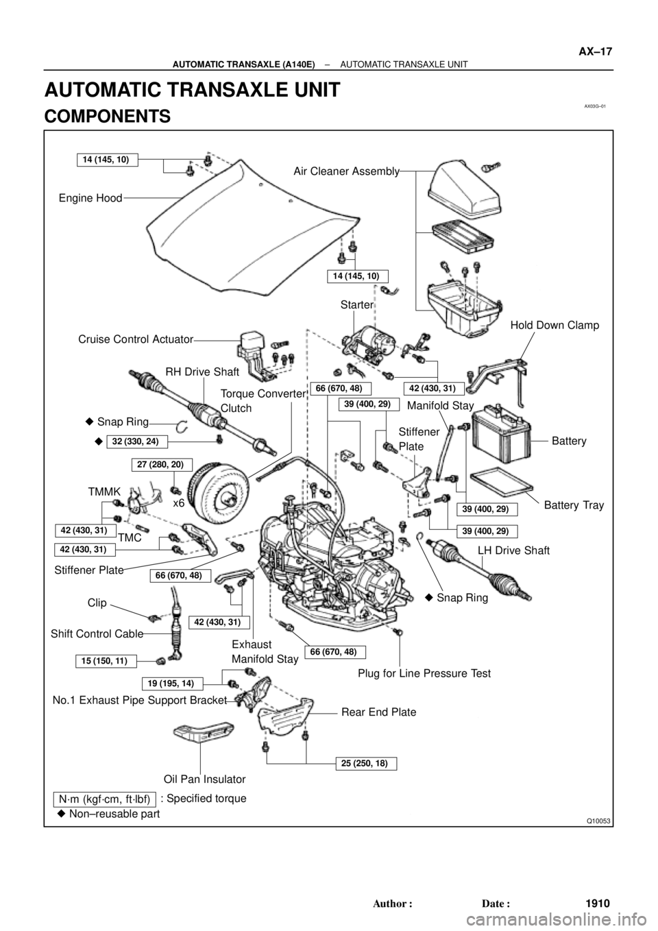
AX03G±01
Q10053
14 (145, 10)
No.1 Exhaust Pipe Support BracketClip Engine Hood
Air Cleaner Assembly
14 (145, 10)
Starter
Cruise Control Actuator
RH Drive Shaft
42 (430, 31)66 (670, 48)
39 (400, 29)
39 (400, 29)
39 (400, 29)
Hold Down Clamp
Manifold Stay
Stiffener
PlateBattery
Battery Tray � Snap Ring
�
32 (330, 24)
27 (280, 20)
Torque Converter
Clutch
x6
42 (430, 31)
42 (430, 31)
Stiffener Plate66 (670, 48)
42 (430, 31)
Exhaust
Manifold Stay66 (670, 48)
� Snap RingLH Drive Shaft
Plug for Line Pressure Test
Rear End Plate
15 (150, 11)
19 (195, 14)
25 (250, 18)
Oil Pan Insulator Shift Control Cable
N´m (kgf´cm, ft´lbf): Specified torque
� Non±reusable partTMMK
TMC
± AUTOMATIC TRANSAXLE (A140E)AUTOMATIC TRANSAXLE UNIT
AX±17
1910 Author�: Date�:
AUTOMATIC TRANSAXLE UNIT
COMPONENTS
Page 113 of 4592

AX03H±01
Q10055
Q00211
Q10056
Q10057
± AUTOMATIC TRANSAXLE (A140E)AUTOMATIC TRANSAXLE UNIT
AX±19
1912 Author�: Date�:
REMOVAL
1. REMOVE BATTERY
2. REMOVE AIR CLEANER ASSEMBLY
3. DISCONNECT THROTTLE CABLE
4. w/ CRUISE CONTROL:
REMOVE CRUISE CONTROL ACTUATOR
(a) Disconnect the connector.
(b) Remove the 3 bolts and disconnect cruise control actua-
tor with the bracket.
5. DISCONNECT OIL COOLER HOSE
6. DISCONNECT VEHICLE SPEED SENSOR CONNEC-
TOR
7. DISCONNECT PARK/NEUTRAL POSITION SWITCH
CONNECTOR
8. DISCONNECT SHIFT SOLENOID VALVE NO.1 AND
NO.2 CONNECTOR
9. DISCONNECT SHIFT SOLENOID VALVE SL CONNEC-
TOR
10. REMOVE 2 FRONT SIDE ENGINE MOUNTING BOLTS
Torque:
TMC made: 80 N´m (820 kgf´cm, 59 ft´lbf)
TMMK made:
Green color bolt: 66 N´m (670 kgf´cm, 48 ft´lbf)
Silver color bolt: 44 N´m (450 kgf´cm, 32 ft´lbf)
11. DISCONNECT 2 GROUND CABLES
12. REMOVE STARTER
(a) Disconnect the connector and remove the nut.
(b) Remove the 2 bolts, shift cable clamp and starter.
Torque: 39 N´m (400 kgf´cm, 29 ft´lbf)
13. REMOVE 3 TRANSAXLE±TO±ENGINE BOLTS
Torque: 66 N´m (670 kgf´cm, 48 ft´lbf)
Page 142 of 4592
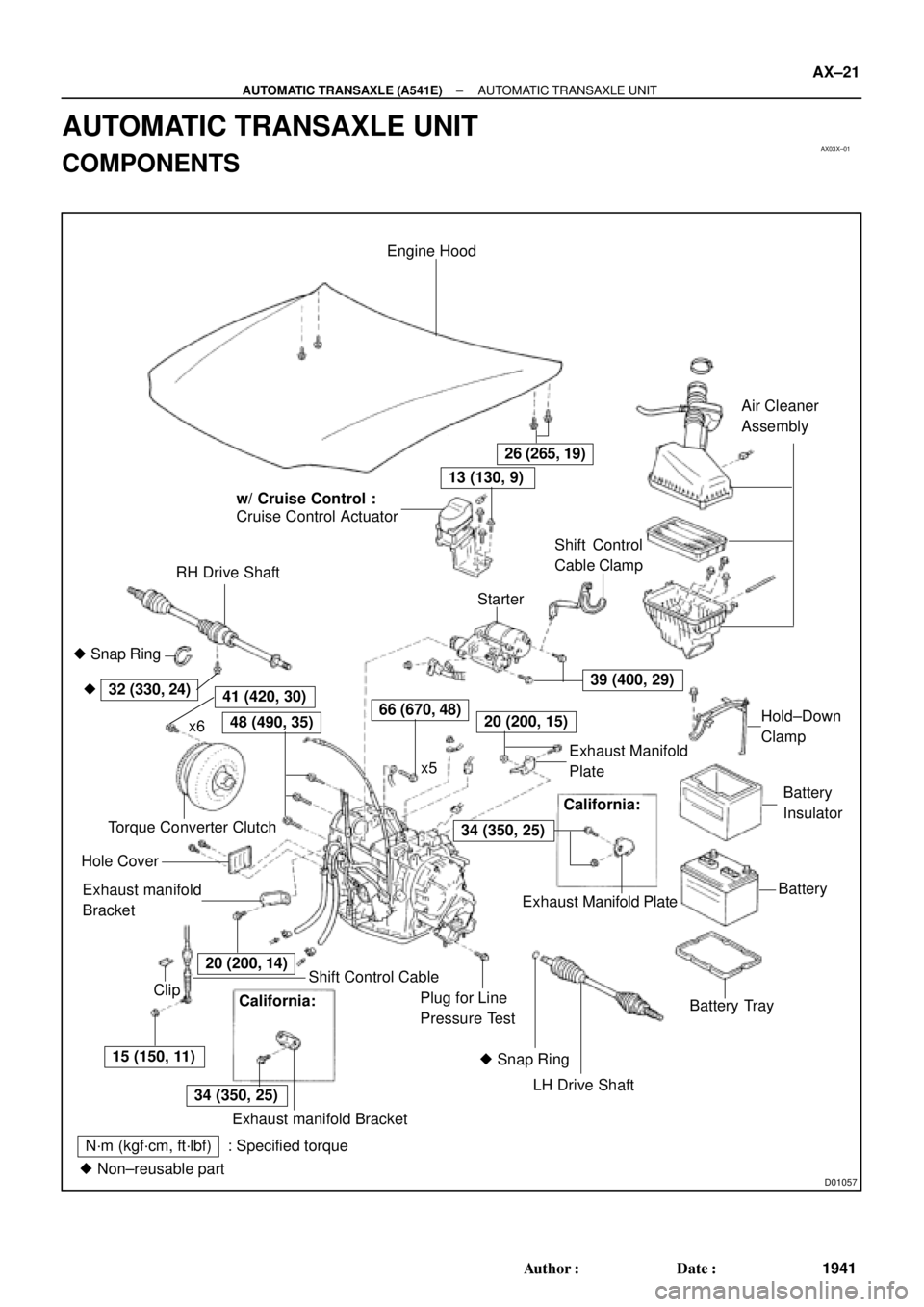
AX03X±01
D01057
Engine Hood
Cruise Control Actuator
RH Drive ShaftAir Cleaner
Assembly
Shift Control Cable
LH Drive Shaft Plug for Line
Pressure TestBattery TrayBatteryBattery
Insulator � Snap Ring
Exhaust manifold
Bracket Hole CoverTorque Converter ClutchShift Control
Cable Clamp
Starter
x6
ClipHold±Down
Clamp
26 (265, 19)
15 (150, 11)
34 (350, 25)
39 (400, 29)
66 (670, 48)48 (490, 35)
32 (330, 24)41 (420, 30)
N´m (kgf´cm, ft´lbf) : Specified torque
� Non±reusable part� Snap Ring �
20 (200, 15)
20 (200, 14)
13 (130, 9)
x5Exhaust Manifold
Plate w/ Cruise Control :
California:
Exhaust Manifold Plate
34 (350, 25)
Exhaust manifold Bracket
California:
± AUTOMATIC TRANSAXLE (A541E)AUTOMATIC TRANSAXLE UNIT
AX±21
1941 Author�: Date�:
AUTOMATIC TRANSAXLE UNIT
COMPONENTS
Page 145 of 4592
Q06478
Q10286
Q06530
Q10038
AX±24
± AUTOMATIC TRANSAXLE (A541E)AUTOMATIC TRANSAXLE UNIT
1944 Author�: Date�:
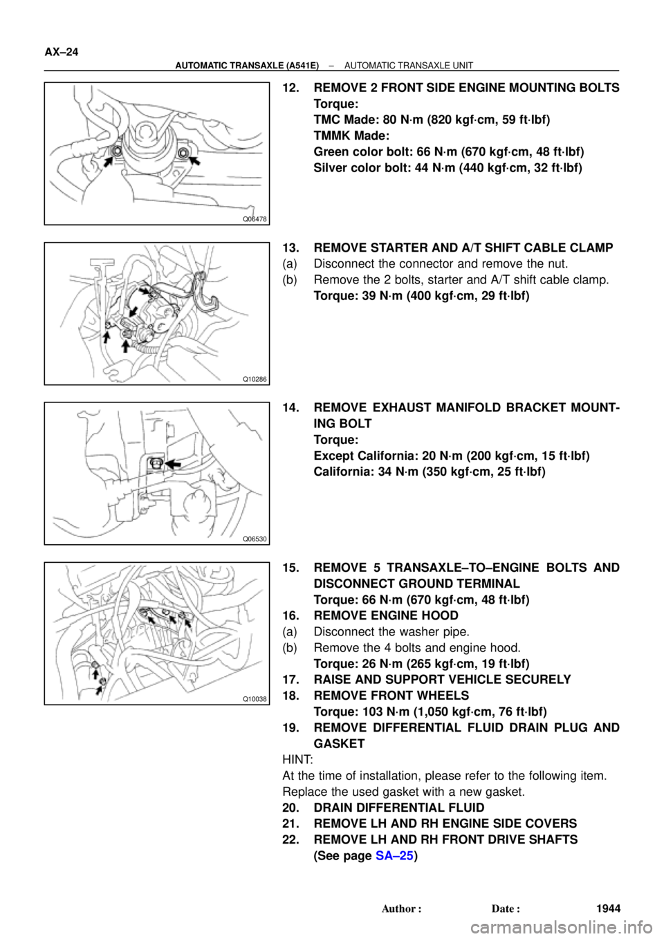
12. REMOVE 2 FRONT SIDE ENGINE MOUNTING BOLTS
Torque:
TMC Made: 80 N´m (820 kgf´cm, 59 ft´lbf)
TMMK Made:
Green color bolt: 66 N´m (670 kgf´cm, 48 ft´lbf)
Silver color bolt: 44 N´m (440 kgf´cm, 32 ft´lbf)
13. REMOVE STARTER AND A/T SHIFT CABLE CLAMP
(a) Disconnect the connector and remove the nut.
(b) Remove the 2 bolts, starter and A/T shift cable clamp.
Torque: 39 N´m (400 kgf´cm, 29 ft´lbf)
14. REMOVE EXHAUST MANIFOLD BRACKET MOUNT-
ING BOLT
Torque:
Except California: 20 N´m (200 kgf´cm, 15 ft´lbf)
California: 34 N´m (350 kgf´cm, 25 ft´lbf)
15. REMOVE 5 TRANSAXLE±TO±ENGINE BOLTS AND
DISCONNECT GROUND TERMINAL
Torque: 66 N´m (670 kgf´cm, 48 ft´lbf)
16. REMOVE ENGINE HOOD
(a) Disconnect the washer pipe.
(b) Remove the 4 bolts and engine hood.
Torque: 26 N´m (265 kgf´cm, 19 ft´lbf)
17. RAISE AND SUPPORT VEHICLE SECURELY
18. REMOVE FRONT WHEELS
Torque: 103 N´m (1,050 kgf´cm, 76 ft´lbf)
19. REMOVE DIFFERENTIAL FLUID DRAIN PLUG AND
GASKET
HINT:
At the time of installation, please refer to the following item.
Replace the used gasket with a new gasket.
20. DRAIN DIFFERENTIAL FLUID
21. REMOVE LH AND RH ENGINE SIDE COVERS
22. REMOVE LH AND RH FRONT DRIVE SHAFTS
(See page SA±25)
Page 168 of 4592
AUTOMATIC TRANSAXLESERVICE SPECIFICATIONS ±
AX±16
Differential
Drive pinion preload (at starting) New bearing
Reused bearing
1.0 ± 1.6 N´m
10 ± 16 kgf´cm 8.7 ± 13.9 in.´lbf
0.5 ± 0.8 N´m
5 ± 8 kgf´cm 4.3 ± 6.9 in.´lbf
Total preload (at starting)
New bearing
Reused bearing
Add drive pinion preload
0.3 ± 0.4 N´m
2.9 ± 4.0 kgf´cm 2.5 ± 3.5 in.´lbf
0.1 ± 0.2 N´m
1.5 ± 2.0 kgf´cm 1.3 ± 1.7 in.´lbf
Pinion to side gear backlash0.05 ± 0.20 mm
0.0020 ± 0.0079 in.
Side gear thrust washer thickness
0.95 mm
0.0374 in.
1.00 mm
0.0394 in.
1.05 mm
0.0413 in.
1.10 mm
0.0433 in.
1.20 mm
0.0427 in.
Page 199 of 4592
AUTOMATIC TRANSAXLECOMPONENT PARTS REMOVAL ±
AX±29
6. REMOVE DIFFERENTIAL CASE, OUTER RACE AND
ADJUSTING SHIM
Remove the differential case, the outer race and the ad-
justing shim from the case.
7. MEASURE DRIVE PINION PRELOAD
Using a torque meter, measure the drive pinion preload.
Preload (at starting):
Reused bearing
0.5 ± 0.8 N´m (5 ± 8 kgf´cm, 4.3 ± 6.9 in.´lbf)
The total preload measured in step 2 minus the drive pin-
ion preload equals 0.1 ± 0.2 N´m (1.5 ± 2.0 kgf´cm, 1.3 ±
1.7in.´lbf).
If the result is not within this specification, the side bearing
preload is bad.
8. REMOVE DRIVE PINION CAP
(a) Remove the drive pinion cap installation bolt.
(b) Using a screwdriver, push out the drive pinion cap.
9. REMOVE COUNTER DRIVEN GEAR
(a) Using a chisel, loosen the staked part of the nut.