Page 2517 of 4592
EC039±05
± EMISSION CONTROL (5S±FE)EMISSION CONTROL SYSTEM
EC±1
1399 Author�: Date�:
EMISSION CONTROL SYSTEM
PURPOSE
The emission control systems are installed to reduce the amount of HC, CO and NOx exhausted from the
engine ((3), (4) and (5)), to prevent the atmospheric release of blow±by gas±containing HC (1) and evapo-
rated fuel containing HC being released from the fuel tank (2).
The function of each system is shown in the following table.
SystemAbbreviationFunction
(1) Positive Crankcase Ventilation
(2) Evaporative Emission Control
(3) Exhaust Gas Recirculation
(4) Three±Way Catalytic Converter
(5) Sequential Multiport Fuel Injection*PCV
EVAP
EGR
TWC
SFIReduces HC
Reduces evaporated HC
Reduces NOx
Reduces HC, CO and NOx
Injects a precisely timed, optimum amount of fuel for reduced
exhaust emissions
Remark: * For inspection and repair of the SFI system, refer to the SFI section in this manual.
Page 2518 of 4592
EC03A±03
B06542
PCV Valve
VSV for EGR
Front TWC
(California)EGR Vacuum Modulator
EGR Valve
TWC (Except California)
Rear TWC (California)
VSV for EVAP
Vent Line
Charcoal Canister
Fuel Tank
EVAP Line
Air Drain Hose
Filler Pipe
Air Inlet LinePurge Line Cutoff Valve
Fill Check Valve
EVAP Service Port
Fuel Tank Cap
VSV for Vapor
Pressure Sensor Vapor Pressure Sensor
EC±2
± EMISSION CONTROL (5S±FE)PARTS LAYOUT AND SCHEMATIC DRAWING
1400 Author�: Date�:
PARTS LAYOUT AND SCHEMATIC DRAWING
LOCATION
Page 2520 of 4592
EC03C±05
B01531
Clean Hose
Cylinder Head Side
B01532
Clean Hose
Intake
Manifold
Side
S01846
EC±4± EMISSION CONTROL (5S±FE)POSITIVE CRANKCASE VENTILATION (PCV)
SYSTEM
1402 Author�: Date�:
POSITIVE CRANKCASE
VENTILATION (PCV) SYSTEM
INSPECTION
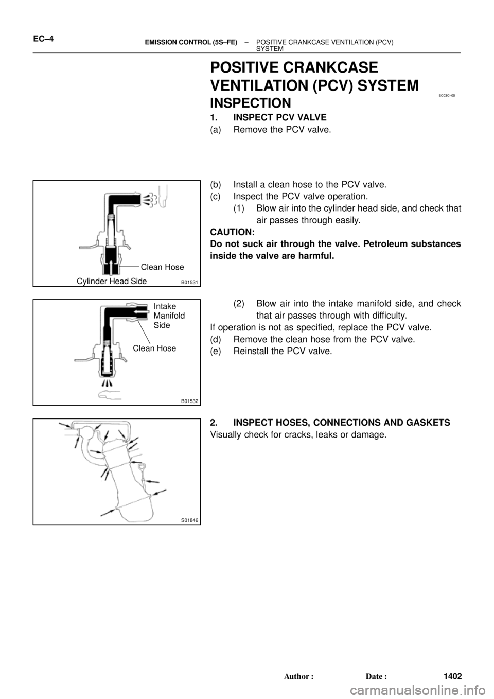
1. INSPECT PCV VALVE
(a) Remove the PCV valve.
(b) Install a clean hose to the PCV valve.
(c) Inspect the PCV valve operation.
(1) Blow air into the cylinder head side, and check that
air passes through easily.
CAUTION:
Do not suck air through the valve. Petroleum substances
inside the valve are harmful.
(2) Blow air into the intake manifold side, and check
that air passes through with difficulty.
If operation is not as specified, replace the PCV valve.
(d) Remove the clean hose from the PCV valve.
(e) Reinstall the PCV valve.
2. INSPECT HOSES, CONNECTIONS AND GASKETS
Visually check for cracks, leaks or damage.
Page 2534 of 4592
EC01U±03
± EMISSION CONTROL (1MZ±FE)EMISSION CONTROL SYSTEM
EC±1
1416 Author�: Date�:
EMISSION CONTROL SYSTEM
PURPOSE
The emission control systems are installed to reduce the amount of CO, HC and NOx exhausted from the
engine ((3), (4), (5) and (6)), to prevent the atmospheric release of blow±by gas±containing HC (1) and evap-
orated fuel containing HC being released from the fuel tank (2).
The function of each system is shown in these table.
SystemAbbreviationFunction
(1) Positive Crankcase Ventilation
(2) Evaporative Emission Control
(3) Exhaust Gas Recirculation
(4) Warm Up Three±Way Catalytic Converter
(5) Three±Way Catalytic Converter
(6) Sequential Multiport Fuel Injection*PCV
EVAP
EGR
WU±TWC
TWC
SFIReduces HC
Reduces evaporated HC
Reduces NOx
Reduces HC, CO and NOx
Reduces HC, CO and NOx
Injects a precisely timed, optimum amount of fuel for reduced
exhaust emissions
Remark: * For inspection and repair of the SFI system, refer to the SF section of this manual.
Page 2537 of 4592
EC01X±03
P02006Cylinder Head sideClean Hose
P02477
Air Intake
Chamber Side
P12931
EC±4± EMISSION CONTROL (1MZ±FE)POSITIVE CRANKCASE VENTILATION (PCV)
SYSTEM
1419 Author�: Date�:
POSITIVE CRANKCASE
VENTILATION (PCV) SYSTEM
INSPECTION
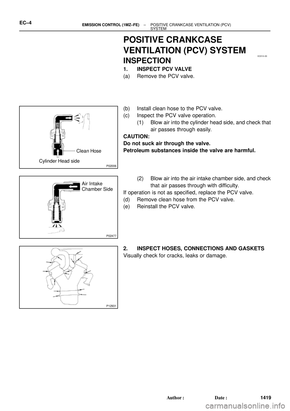
1. INSPECT PCV VALVE
(a) Remove the PCV valve.
(b) Install clean hose to the PCV valve.
(c) Inspect the PCV valve operation.
(1) Blow air into the cylinder head side, and check that
air passes through easily.
CAUTION:
Do not suck air through the valve.
Petroleum substances inside the valve are harmful.
(2) Blow air into the air intake chamber side, and check
that air passes through with difficulty.
If operation is not as specified, replace the PCV valve.
(d) Remove clean hose from the PCV valve.
(e) Reinstall the PCV valve.
2. INSPECT HOSES, CONNECTIONS AND GASKETS
Visually check for cracks, leaks or damage.
Page 2553 of 4592

EM±2
± ENGINE MECHANICAL (5S±FE)CO/HC
1174 Author�: Date�:
If the CO/HC concentration does not comply with regulations,
troubleshoot in the order given below.
(1) Check oxygen sensor operation.
(See page DI±66)
(2) See the table below for possible causes, then in-
spect and correct the applicable causes if neces-
sary.
COHCSymptomCauses
NormalHighRough idle1. Faulty ignitions:
� Incorrect timing
� Fouled, shorted or improperly gapped plugs
� Open or crossed hi
gh±tension cords� Oen or crossed high±tension cords
2. Incorrect valve clearance
3. Leaky EGR valve
4. Leaky intake and exhaust valves
5. Leaky cylinder
LowHighRough idle
(Fluctuating HC reading)1. Vacuum leaks:
� PCV hose
� EGR valve
� Intake manifold
� Throttle body
� IAC valve
� Brake booster line
2. Lean mixture causing misfire
HighHighRough idle
(Black smoke from exhaust)1. Restricted air filter
2. Faulty SFI system
� Faulty pressure regulator
� Defective ECT sensor
� Defective IAT sensor
� Faulty ECM
� Faulty injector
� Faulty throttle position sensor
� MAP sensor
Page 2555 of 4592
EM07Z±03
S05289
(c)
(d) (e)
S05590
Turn
P03443
1 11 122
33 EM±4
± ENGINE MECHANICAL (5S±FE)VALVE CLEARANCE
1176 Author�: Date�:
VALVE CLEARANCE
INSPECTION
HINT:
Inspect and adjust the valve clearance when the engine is cold.
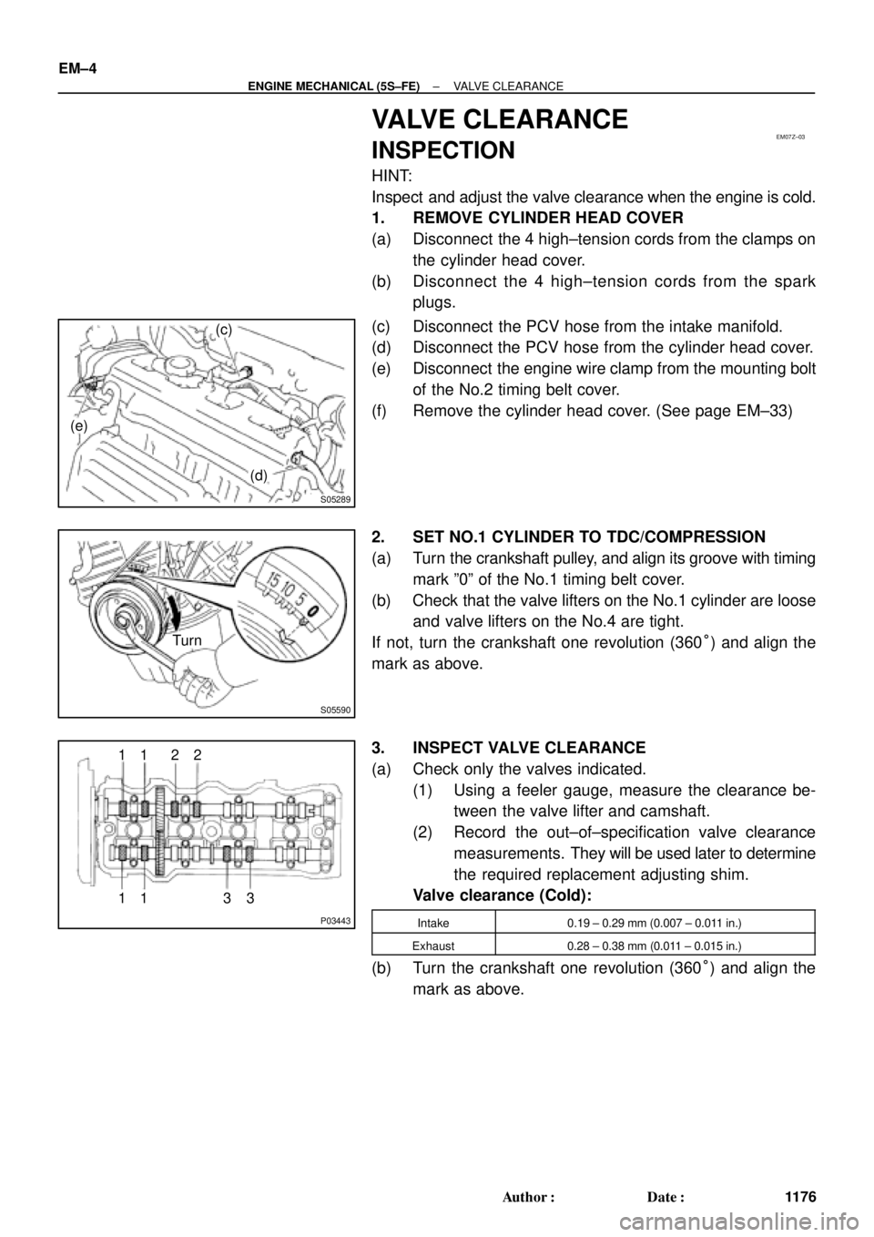
1. REMOVE CYLINDER HEAD COVER
(a) Disconnect the 4 high±tension cords from the clamps on
the cylinder head cover.
(b) Disconnect the 4 high±tension cords from the spark
plugs.
(c) Disconnect the PCV hose from the intake manifold.
(d) Disconnect the PCV hose from the cylinder head cover.
(e) Disconnect the engine wire clamp from the mounting bolt
of the No.2 timing belt cover.
(f) Remove the cylinder head cover. (See page EM±33)
2. SET NO.1 CYLINDER TO TDC/COMPRESSION
(a) Turn the crankshaft pulley, and align its groove with timing
mark º0º of the No.1 timing belt cover.
(b) Check that the valve lifters on the No.1 cylinder are loose
and valve lifters on the No.4 are tight.
If not, turn the crankshaft one revolution (360°) and align the
mark as above.
3. INSPECT VALVE CLEARANCE
(a) Check only the valves indicated.
(1) Using a feeler gauge, measure the clearance be-
tween the valve lifter and camshaft.
(2) Record the out±of±specification valve clearance
measurements. They will be used later to determine
the required replacement adjusting shim.
Valve clearance (Cold):
Intake0.19 ± 0.29 mm (0.007 ± 0.011 in.)
Exhaust0.28 ± 0.38 mm (0.011 ± 0.015 in.)
(b) Turn the crankshaft one revolution (360°) and align the
mark as above.
Page 2557 of 4592
P13989
SST (A)
SST (B)
S05289
(b)
(c)
(d) EM±6
± ENGINE MECHANICAL (5S±FE)VALVE CLEARANCE
1178 Author�: Date�:
Exhaust: N = T + (A ± 0.33 mm (0.013 in.))
(3) Select a new shim with a thickness as close as pos-
sible to the calculated value.
HINT:
Shims are available in 17 sizes in increments of 0.05 mm
(0.0020 in.), from 2.50 mm (0.0984 in.) to 3.30 mm (0.1299 in.).
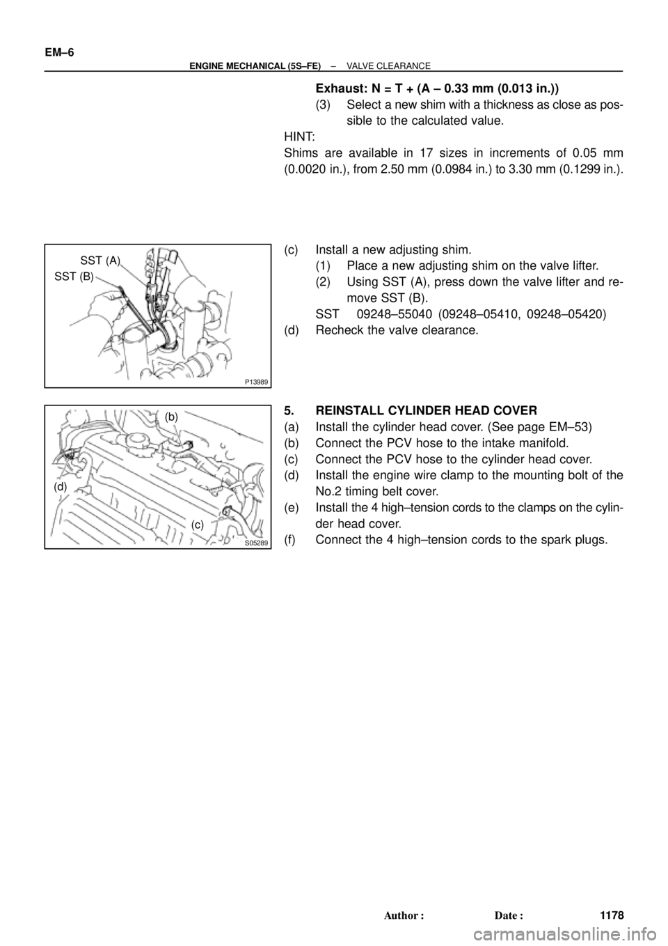
(c) Install a new adjusting shim.
(1) Place a new adjusting shim on the valve lifter.
(2) Using SST (A), press down the valve lifter and re-
move SST (B).
SST 09248±55040 (09248±05410, 09248±05420)
(d) Recheck the valve clearance.
5. REINSTALL CYLINDER HEAD COVER
(a) Install the cylinder head cover. (See page EM±53)
(b) Connect the PCV hose to the intake manifold.
(c) Connect the PCV hose to the cylinder head cover.
(d) Install the engine wire clamp to the mounting bolt of the
No.2 timing belt cover.
(e) Install the 4 high±tension cords to the clamps on the cylin-
der head cover.
(f) Connect the 4 high±tension cords to the spark plugs.