Page 2352 of 4592
F08572
1
2
F08573
1
2
DI±200
± DIAGNOSTICSANTI±LOCK BRAKE SYSTEM
INSPECTION PROCEDURE
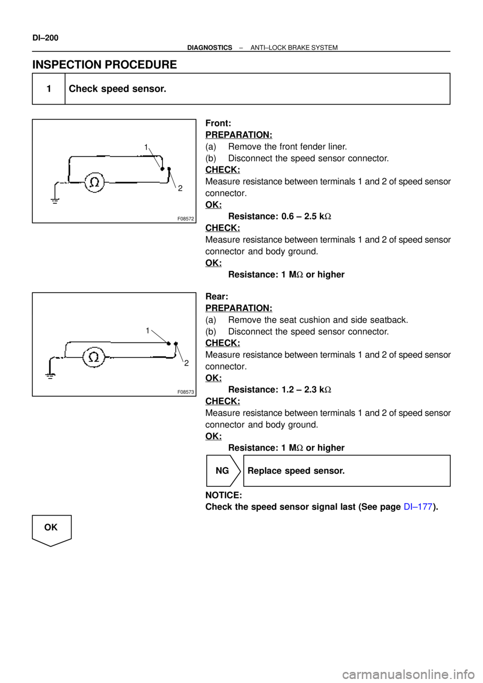
1 Check speed sensor.
Front:
PREPARATION:
(a) Remove the front fender liner.
(b) Disconnect the speed sensor connector.
CHECK:
Measure resistance between terminals 1 and 2 of speed sensor
connector.
OK:
Resistance: 0.6 ± 2.5 kW
CHECK:
Measure resistance between terminals 1 and 2 of speed sensor
connector and body ground.
OK:
Resistance: 1 MW or higher
Rear:
PREPARATION:
(a) Remove the seat cushion and side seatback.
(b) Disconnect the speed sensor connector.
CHECK:
Measure resistance between terminals 1 and 2 of speed sensor
connector.
OK:
Resistance: 1.2 ± 2.3 kW
CHECK:
Measure resistance between terminals 1 and 2 of speed sensor
connector and body ground.
OK:
Resistance: 1 MW or higher
NG Replace speed sensor.
NOTICE:
Check the speed sensor signal last (See page DI±177).
OK
Page 3191 of 4592
RS05G±02
H08245
Headrest
Headrest Support
Side Airbag
Assembly
Front Seatback Cover
Hinge Cover
Front Seat Cushion Shield
Release Handle
Power adjuster type:
Front Seat
Cushion Shield
Front Seat Cushion
Lower Shield Vartical Adjuster Knob Front Seat Cushion
Inner Shield
Front Seat Cushion
Lower Shield
37 (375, 27)
15 (150, 11)
18 (185, 13)
N´m (kgf´cm, ft´lbf): Specified torqueFront Seatback Assembly
Front Seat Cushion
Assembly
Seat Track Cover
± SUPPLEMENTAL RESTRAINT SYSTEMSIDE AIRBAG ASSEMBLY (TMC Made)
RS±39
2184 Author�: Date�:
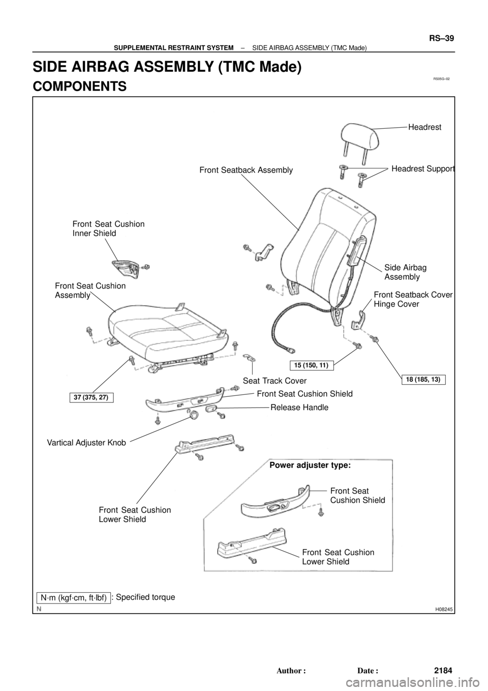
SIDE AIRBAG ASSEMBLY (TMC Made)
COMPONENTS
Page 3192 of 4592
RS0EU±01
H02270
H02259
RS±40
± SUPPLEMENTAL RESTRAINT SYSTEMSIDE AIRBAG ASSEMBLY (TMC Made)
2185 Author�: Date�:
REMOVAL
NOTICE:
�If the wiring connector of the SRS is disconnected
and the ignition switch is in ON or ACC position, DTCs
will be recorded.
�Never use the airbag parts from another vehicle.
When replacing parts, replace them with new parts.
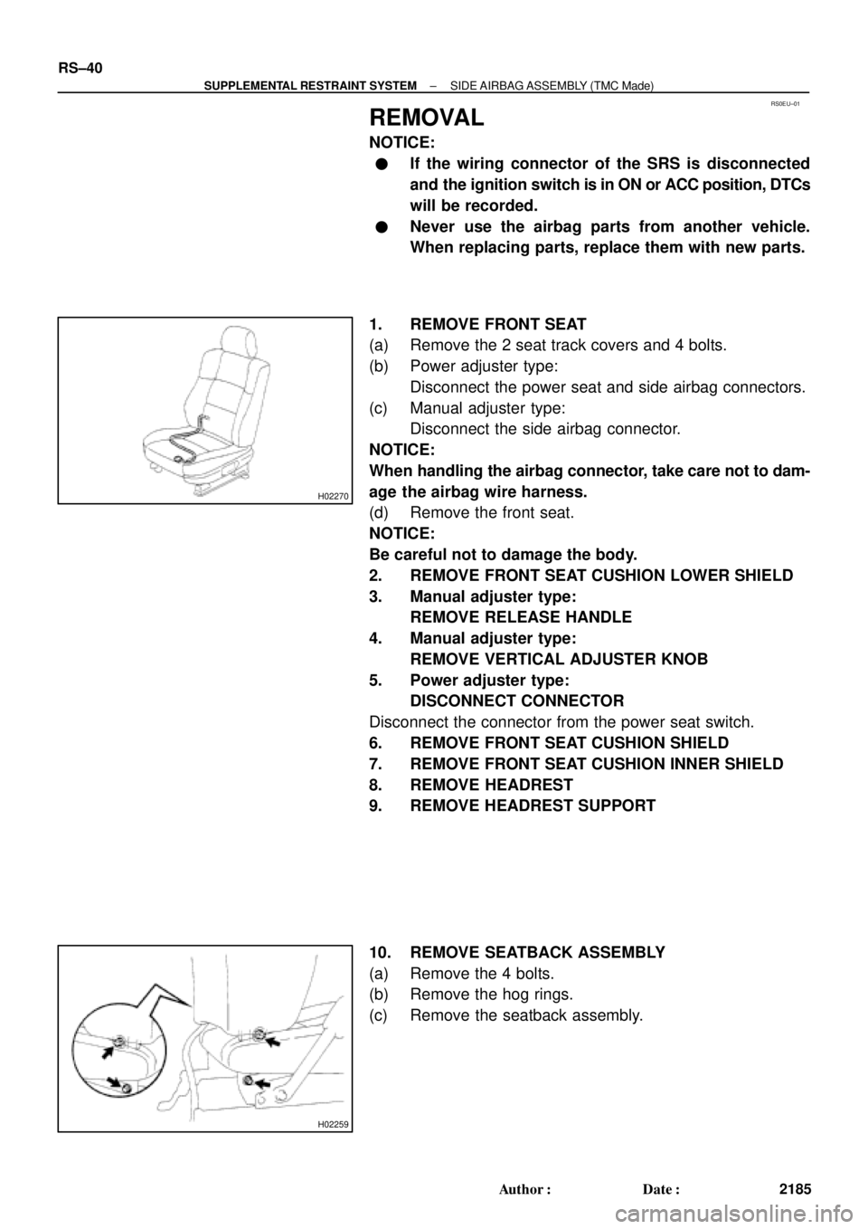
1. REMOVE FRONT SEAT
(a) Remove the 2 seat track covers and 4 bolts.
(b) Power adjuster type:
Disconnect the power seat and side airbag connectors.
(c) Manual adjuster type:
Disconnect the side airbag connector.
NOTICE:
When handling the airbag connector, take care not to dam-
age the airbag wire harness.
(d) Remove the front seat.
NOTICE:
Be careful not to damage the body.
2. REMOVE FRONT SEAT CUSHION LOWER SHIELD
3. Manual adjuster type:
REMOVE RELEASE HANDLE
4. Manual adjuster type:
REMOVE VERTICAL ADJUSTER KNOB
5. Power adjuster type:
DISCONNECT CONNECTOR
Disconnect the connector from the power seat switch.
6. REMOVE FRONT SEAT CUSHION SHIELD
7. REMOVE FRONT SEAT CUSHION INNER SHIELD
8. REMOVE HEADREST
9. REMOVE HEADREST SUPPORT
10. REMOVE SEATBACK ASSEMBLY
(a) Remove the 4 bolts.
(b) Remove the hog rings.
(c) Remove the seatback assembly.
Page 3193 of 4592
RS05I±02
H01608
Cross Section
H08274
± SUPPLEMENTAL RESTRAINT SYSTEMSIDE AIRBAG ASSEMBLY (TMC Made)
RS±41
2186 Author�: Date�:
INSPECTION
1. VEHICLE NOT INVOLVED IN COLLISION
(a) Do a diagnostic system check. (See page DI±626)
(b) Do a visual check which includes the following items with
the seatback assembly installed in the vehicle.
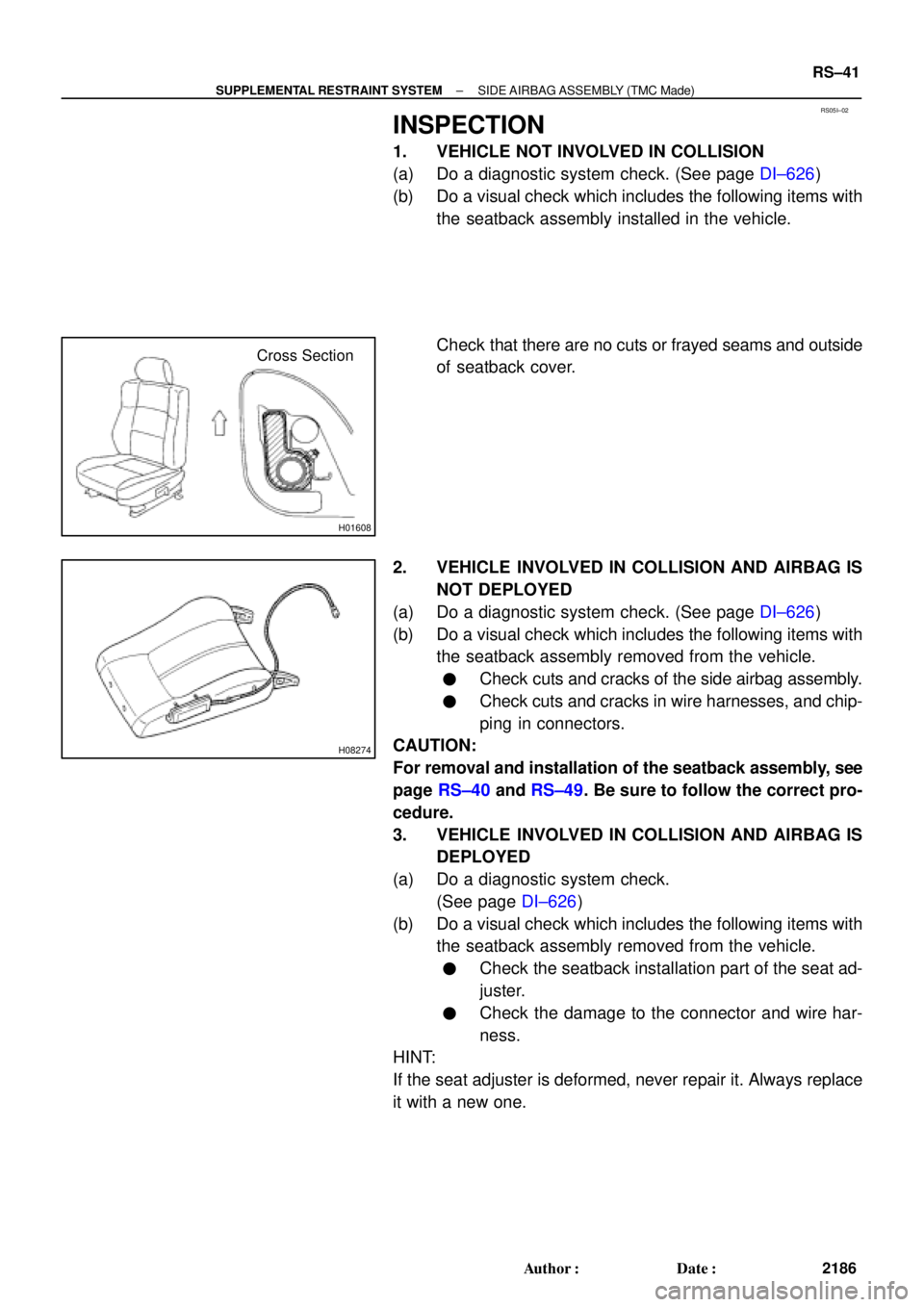
Check that there are no cuts or frayed seams and outside
of seatback cover.
2. VEHICLE INVOLVED IN COLLISION AND AIRBAG IS
NOT DEPLOYED
(a) Do a diagnostic system check. (See page DI±626)
(b) Do a visual check which includes the following items with
the seatback assembly removed from the vehicle.
�Check cuts and cracks of the side airbag assembly.
�Check cuts and cracks in wire harnesses, and chip-
ping in connectors.
CAUTION:
For removal and installation of the seatback assembly, see
page RS±40 and RS±49. Be sure to follow the correct pro-
cedure.
3. VEHICLE INVOLVED IN COLLISION AND AIRBAG IS
DEPLOYED
(a) Do a diagnostic system check.
(See page DI±626)
(b) Do a visual check which includes the following items with
the seatback assembly removed from the vehicle.
�Check the seatback installation part of the seat ad-
juster.
�Check the damage to the connector and wire har-
ness.
HINT:
If the seat adjuster is deformed, never repair it. Always replace
it with a new one.
Page 3196 of 4592
AB0163
Wire Harness
Diameter
Stripped Wire Harness Section RS±44
± SUPPLEMENTAL RESTRAINT SYSTEMSIDE AIRBAG ASSEMBLY (TMC Made)
2189 Author�: Date�:
(e) Dispose of side airbag assembly.
CAUTION:
�The side airbag assembly is very hot when the airbag
is deployed, so leave it alone for at least 30 minutes
after deployment.
�Use gloves and safety glasses when handling a side
airbag assembly with the deployed airbag.
�Do not apply water, etc. to a side airbag assembly with
the deployed airbag.
�Always wash your hands with water after completing
the operation.
When scrapping a vehicle, deploy the airbag and scrap
the vehicle with the side airbag assembly still installed.
2. DEPLOYMENT WHEN DISPOSING OF SIDE AIRBAG
ASSEMBLY
NOTICE:
�When disposing of the side airbag assembly only,
never use the customer's vehicle to deploy the air-
bag.
�Be sure to follow the procedure given below when de-
ploying the airbag.
HINT:
Have a battery ready as the power source to deploy the airbag.
(a) Remove the seatback assembly.
(b) Remove the side airbag assembly from the seatback as-
sembly.
CAUTION:
Store the side airbag assembly with the airbag deployment
side facing upward.
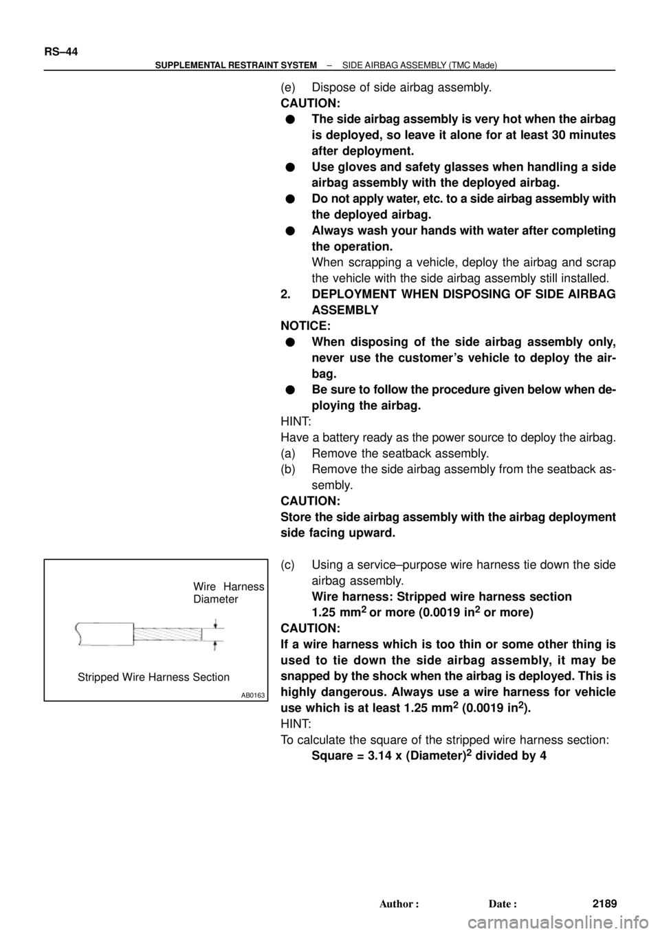
(c) Using a service±purpose wire harness tie down the side
airbag assembly.
Wire harness: Stripped wire harness section
1.25 mm
2
or more (0.0019 in2 or more)
CAUTION:
If a wire harness which is too thin or some other thing is
used to tie down the side airbag assembly, it may be
snapped by the shock when the airbag is deployed. This is
highly dangerous. Always use a wire harness for vehicle
use which is at least 1.25 mm
2 (0.0019 in2).
HINT:
To calculate the square of the stripped wire harness section:
Square = 3.14 x (Diameter)
2 divided by 4
Page 3200 of 4592
RS05K±02
RS±48
± SUPPLEMENTAL RESTRAINT SYSTEMSIDE AIRBAG ASSEMBLY (TMC Made)
2193 Author�: Date�:
REPLACEMENT
REPLACEMENT REQUIREMENTS
In the following cases, replace the seatback assembly or seatback cover.
CaseReplacing part
If the side airbag has been deployed.Seatback assembly
If the side airbag assembly has been found to be faulty in troubleshooting.Seatback assembly
If the side airbag assembly has cuts during checking items.
(See page RS±41)Seatback assembly
If the seatback cover has cuts and frayed seams during checking items.
(See page RS±41)Seatback cover
If the side airbag assembly has been found to be faulty during checking
items. (See page RS±41)Seatback assembly
If the seatback cover has been found to be faulty during checking items.
(See page RS±41)Seatback cover
If the seatback assembly has been dropped.Seatback assembly
CAUTION:
For removal and installation of the seatback assembly, see page RS±40 and RS±49. Be sure to follow
the correct procedure.
Page 3201 of 4592
RS0EV±01
H02259
A
B
± SUPPLEMENTAL RESTRAINT SYSTEMSIDE AIRBAG ASSEMBLY (TMC Made)
RS±49
2194 Author�: Date�:
INSTALLATION
NOTICE:
Never use airbag parts from another vehicle. When replac-
ing parts, replace them with new parts.
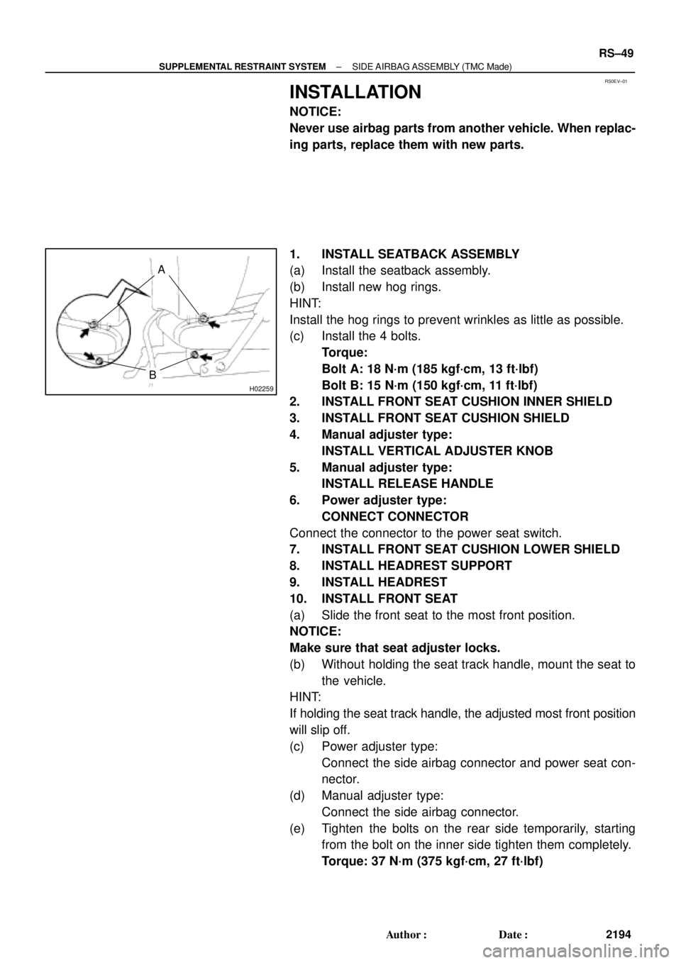
1. INSTALL SEATBACK ASSEMBLY
(a) Install the seatback assembly.
(b) Install new hog rings.
HINT:
Install the hog rings to prevent wrinkles as little as possible.
(c) Install the 4 bolts.
Torque:
Bolt A: 18 N´m (185 kgf´cm, 13 ft´lbf)
Bolt B: 15 N´m (150 kgf´cm, 11 ft´lbf)
2. INSTALL FRONT SEAT CUSHION INNER SHIELD
3. INSTALL FRONT SEAT CUSHION SHIELD
4. Manual adjuster type:
INSTALL VERTICAL ADJUSTER KNOB
5. Manual adjuster type:
INSTALL RELEASE HANDLE
6. Power adjuster type:
CONNECT CONNECTOR
Connect the connector to the power seat switch.
7. INSTALL FRONT SEAT CUSHION LOWER SHIELD
8. INSTALL HEADREST SUPPORT
9. INSTALL HEADREST
10. INSTALL FRONT SEAT
(a) Slide the front seat to the most front position.
NOTICE:
Make sure that seat adjuster locks.
(b) Without holding the seat track handle, mount the seat to
the vehicle.
HINT:
If holding the seat track handle, the adjusted most front position
will slip off.
(c) Power adjuster type:
Connect the side airbag connector and power seat con-
nector.
(d) Manual adjuster type:
Connect the side airbag connector.
(e) Tighten the bolts on the rear side temporarily, starting
from the bolt on the inner side tighten them completely.
Torque: 37 N´m (375 kgf´cm, 27 ft´lbf)
Page 3203 of 4592
RS05M±03
H08246
Seatback AssemblyHeadrest
Headrest Support
Side Airbag
Assembly
Seat Truck Cover
Front Seat Cushion Shield
Release Handle
Power adjuster type:
Front Seat
Cushion Shield Front Seat Cushion
Lower Shield Vartical Adjuster Knob
Sub Wire HarnessFront Seat Cushion
Lower Shield
37 (375, 27)
N´m (kgf´cm, ft´lbf) : Specified torque
Front Seat Cushion Assembly
± SUPPLEMENTAL RESTRAINT SYSTEMSIDE AIRBAG ASSEMBLY (TMMK Made)
RS±51
2196 Author�: Date�:
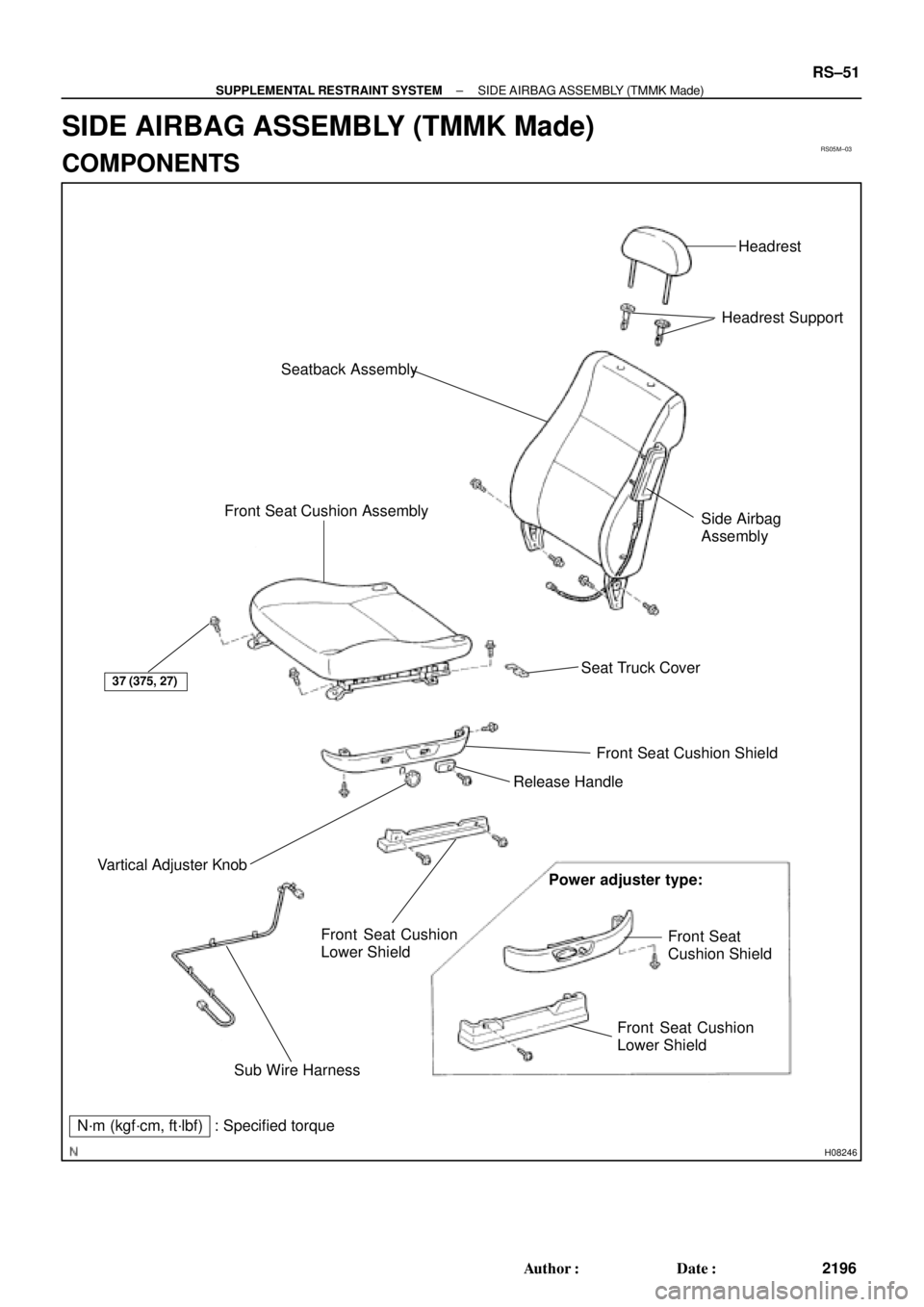
SIDE AIRBAG ASSEMBLY (TMMK Made)
COMPONENTS