Page 1006 of 4592
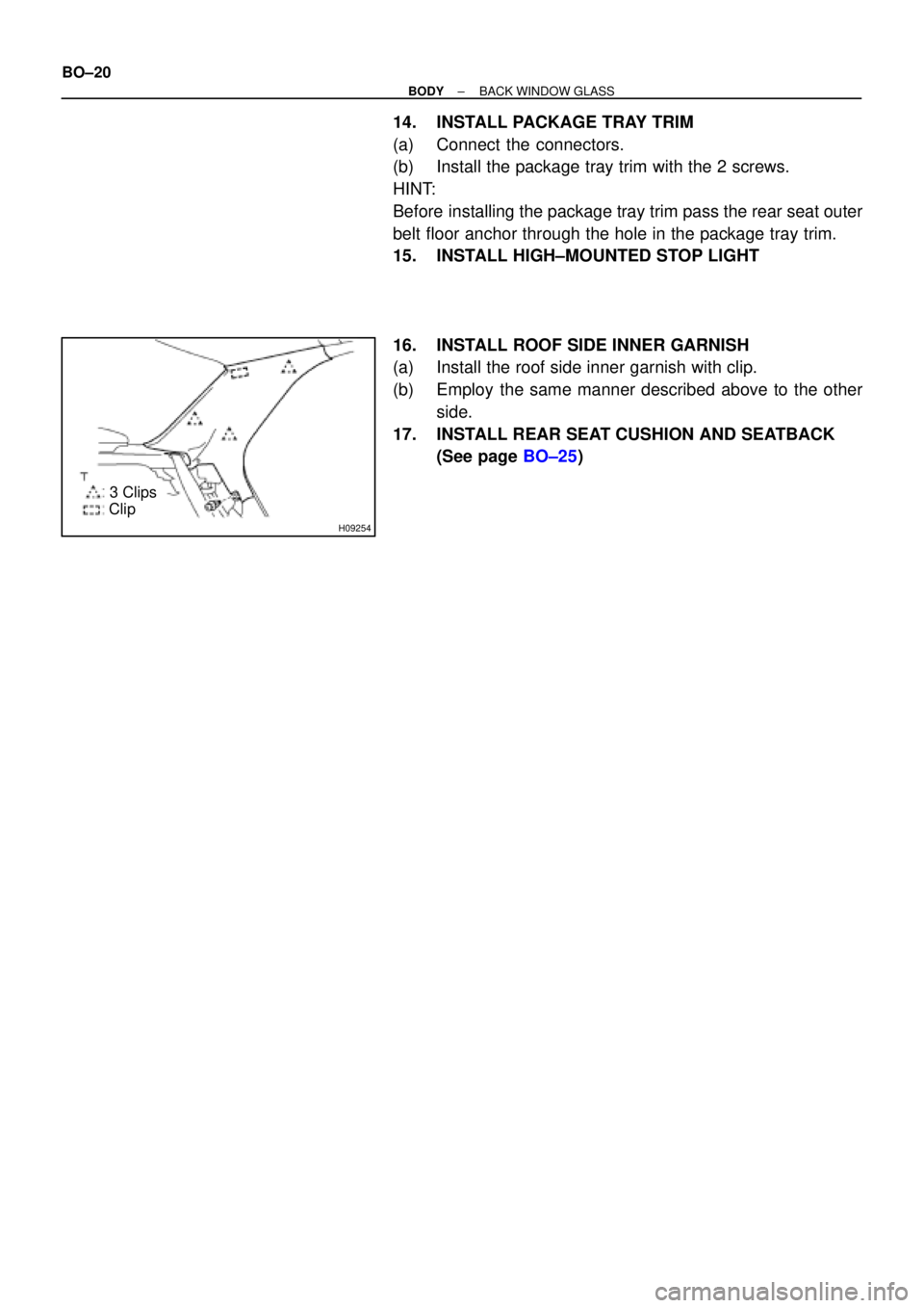
H09254
3 Clips
Clip BO±20
± BODYBACK WINDOW GLASS
14. INSTALL PACKAGE TRAY TRIM
(a) Connect the connectors.
(b) Install the package tray trim with the 2 screws.
HINT:
Before installing the package tray trim pass the rear seat outer
belt floor anchor through the hole in the package tray trim.
15. INSTALL HIGH±MOUNTED STOP LIGHT
16. INSTALL ROOF SIDE INNER GARNISH
(a) Install the roof side inner garnish with clip.
(b) Employ the same manner described above to the other
side.
17. INSTALL REAR SEAT CUSHION AND SEATBACK
(See page BO±25)
Page 1007 of 4592
BO2DV±02
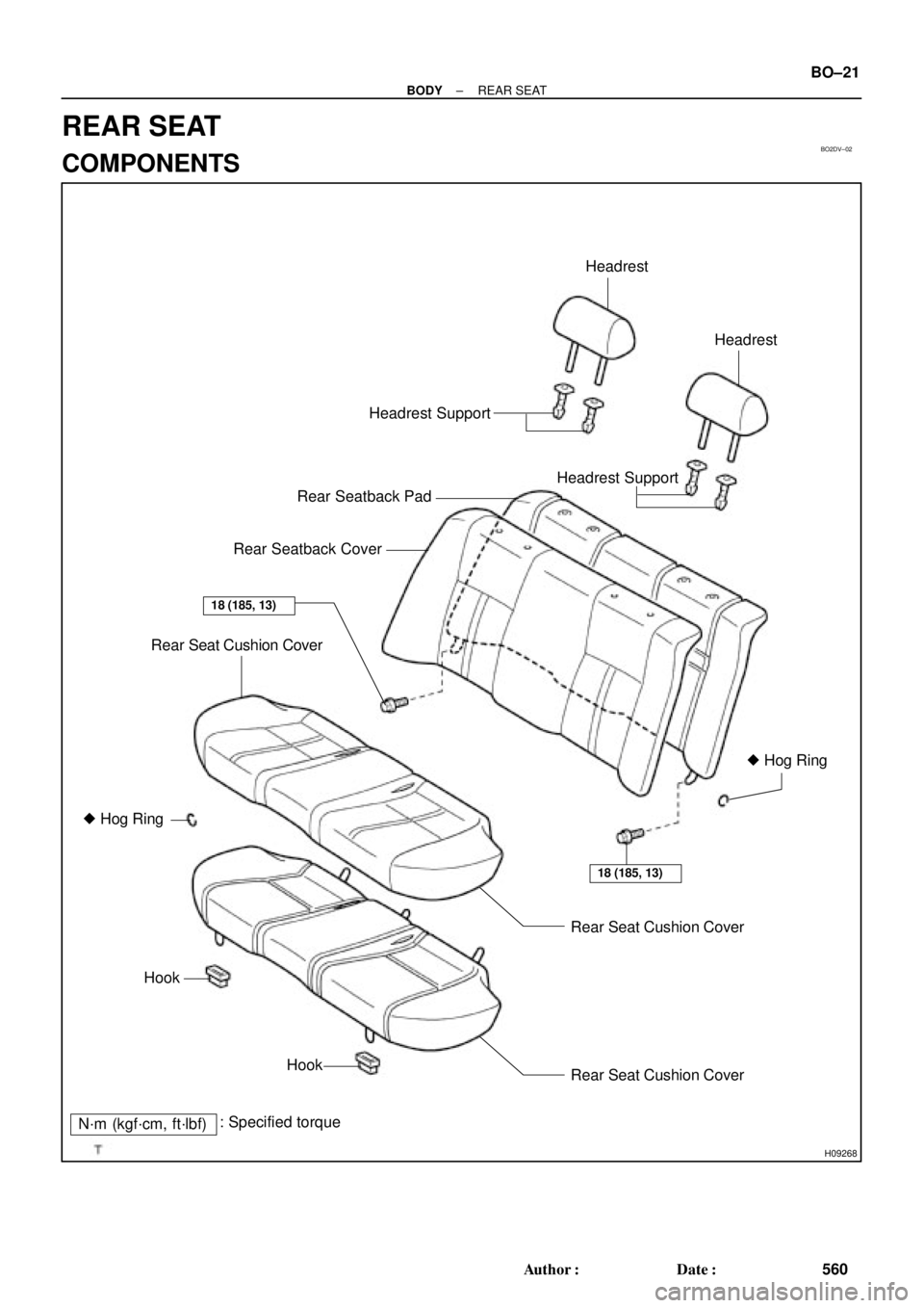
H09268
Headrest SupportHeadrest
Headrest
Rear Seatback Pad
Rear Seatback Cover
Rear Seat Cushion Cover
� Hog Ring
HookRear Seat Cushion Cover Headrest Support
Hook
Rear Seat Cushion Cover
18 (185, 13)
N´m (kgf´cm, ft´lbf): Specified torque� Hog Ring
18 (185, 13)
± BODYREAR SEAT
BO±21
560 Author�: Date�:
REAR SEAT
COMPONENTS
Page 1008 of 4592
BO2DW±01
BO±22
± BODYREAR SEAT
REMOVAL
1. REMOVE REAR SEAT CUSHION ASSEMBLY
Pull up the front part of seat cushion assembly to remove the rear seat cushion assembly.
HINT:
When removing the rear seat cushion assembly, pass the rear seat inner with center belt through the hole
on the seatback.
2. REMOVE REAR SEATBACK ASSEMBLY
(a) Remove the 3 bolts.
Torque: 18 N´m (185 kgf´cm, 13 ft´lbf)
HINT:
At the time of reassembly, please refer to the following item. When installing hog rings, take care to prevent
wrinkles as little as possible.
(b) Pull up the seatback assembly to remove it.
Page 1009 of 4592
BO2DX±01
± BODYREAR SEAT
BO±23
DISASSEMBLY
1. REMOVE HEADRESTS AND HEADREST SUPPORTS
2. REMOVE SEATBACK COVER
Remove the hog rings and seatback cover from the seatback pad.
3. REMOVE SEAT CUSHION COVER
Remove the hog rings and seat cushion cover from the seat cushion pad.
Page 1085 of 4592
BR0BU±03
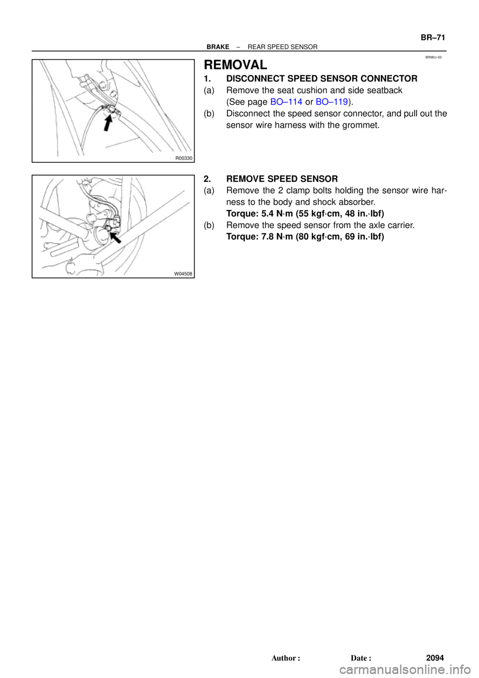
R00330
W04508
± BRAKEREAR SPEED SENSOR
BR±71
2094 Author�: Date�:
REMOVAL
1. DISCONNECT SPEED SENSOR CONNECTOR
(a) Remove the seat cushion and side seatback
(See page BO±114 or BO±119).
(b) Disconnect the speed sensor connector, and pull out the
sensor wire harness with the grommet.
2. REMOVE SPEED SENSOR
(a) Remove the 2 clamp bolts holding the sensor wire har-
ness to the body and shock absorber.
Torque: 5.4 N´m (55 kgf´cm, 48 in.´lbf)
(b) Remove the speed sensor from the axle carrier.
Torque: 7.8 N´m (80 kgf´cm, 69 in.´lbf)
Page 1728 of 4592
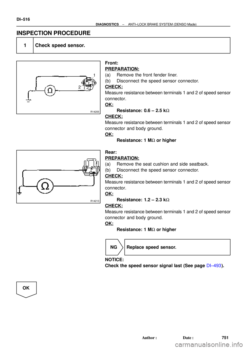
R14205
1
2
R14213
12 12
12
12
12
1212
DI±516
± DIAGNOSTICSANTI±LOCK BRAKE SYSTEM (DENSO Made)
751 Author�: Date�:
INSPECTION PROCEDURE
1 Check speed sensor.
Front:
PREPARATION:
(a) Remove the front fender liner.
(b) Disconnect the speed sensor connector.
CHECK:
Measure resistance between terminals 1 and 2 of speed sensor
connector.
OK:
Resistance: 0.6 ± 2.5 kW
CHECK:
Measure resistance between terminals 1 and 2 of speed sensor
connector and body ground.
OK:
Resistance: 1 MW or higher
Rear:
PREPARATION:
(a) Remove the seat cushion and side seatback.
(b) Disconnect the speed sensor connector.
CHECK:
Measure resistance between terminals 1 and 2 of speed sensor
connector.
OK:
Resistance: 1.2 ± 2.3 kW
CHECK:
Measure resistance between terminals 1 and 2 of speed sensor
connector and body ground.
OK:
Resistance: 1 MW or higher
NG Replace speed sensor.
NOTICE:
Check the speed sensor signal last (See page DI±493).
OK
Page 1766 of 4592
R14205
1
2
R14213
12 12
12
12
12
1212
DI±554
± DIAGNOSTICSANTI±LOCK BRAKE SYSTEM (BOSCH Made)
789 Author�: Date�:
INSPECTION PROCEDURE
1 Check speed sensor.
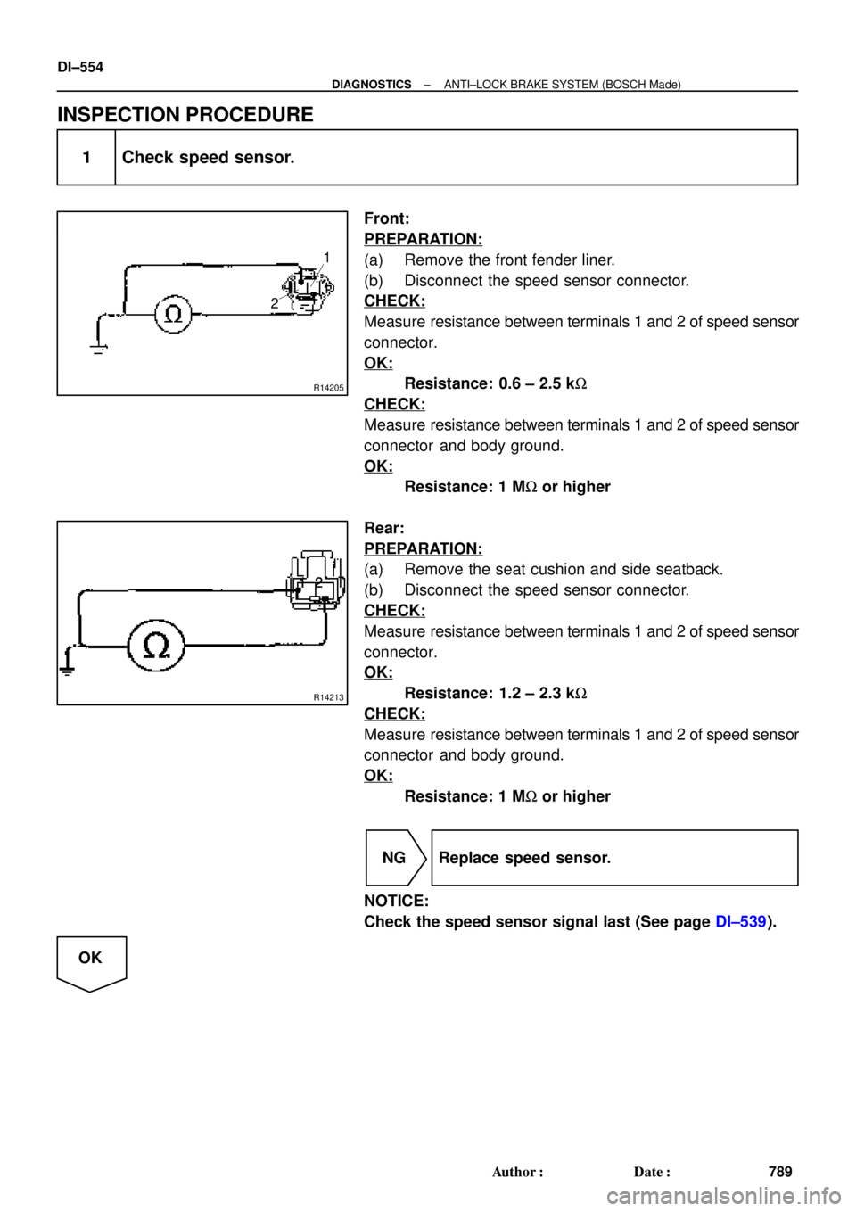
Front:
PREPARATION:
(a) Remove the front fender liner.
(b) Disconnect the speed sensor connector.
CHECK:
Measure resistance between terminals 1 and 2 of speed sensor
connector.
OK:
Resistance: 0.6 ± 2.5 kW
CHECK:
Measure resistance between terminals 1 and 2 of speed sensor
connector and body ground.
OK:
Resistance: 1 MW or higher
Rear:
PREPARATION:
(a) Remove the seat cushion and side seatback.
(b) Disconnect the speed sensor connector.
CHECK:
Measure resistance between terminals 1 and 2 of speed sensor
connector.
OK:
Resistance: 1.2 ± 2.3 kW
CHECK:
Measure resistance between terminals 1 and 2 of speed sensor
connector and body ground.
OK:
Resistance: 1 MW or higher
NG Replace speed sensor.
NOTICE:
Check the speed sensor signal last (See page DI±539).
OK
Page 1807 of 4592
R14205
1
2
R14213
12
12
12
12
12
1212
± DIAGNOSTICSABS & TRACTION CONTROL SYSTEM
DI±595
830 Author�: Date�:
INSPECTION PROCEDURE
1 Check speed sensor.
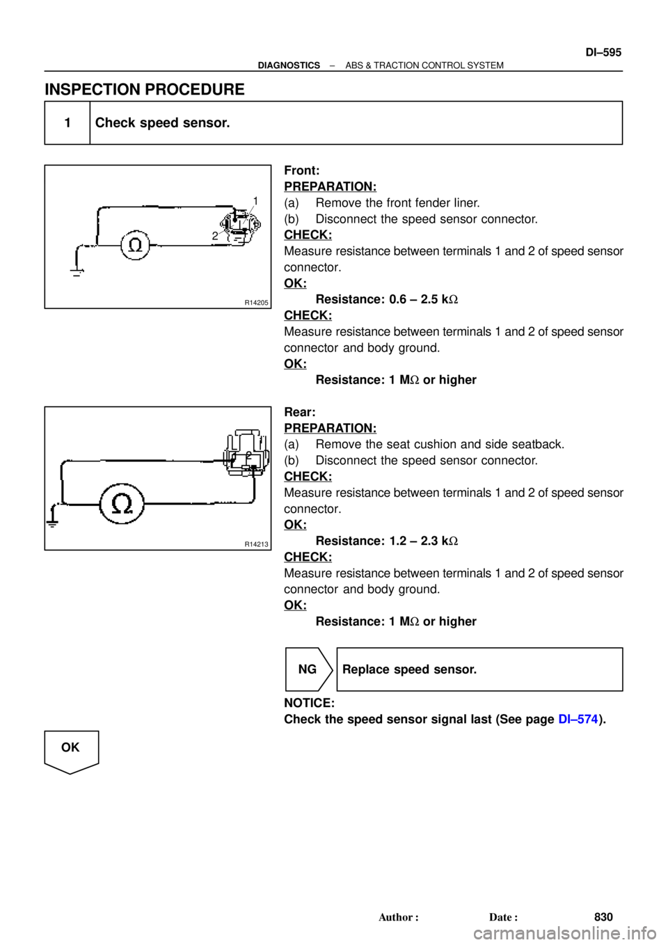
Front:
PREPARATION:
(a) Remove the front fender liner.
(b) Disconnect the speed sensor connector.
CHECK:
Measure resistance between terminals 1 and 2 of speed sensor
connector.
OK:
Resistance: 0.6 ± 2.5 kW
CHECK:
Measure resistance between terminals 1 and 2 of speed sensor
connector and body ground.
OK:
Resistance: 1 MW or higher
Rear:
PREPARATION:
(a) Remove the seat cushion and side seatback.
(b) Disconnect the speed sensor connector.
CHECK:
Measure resistance between terminals 1 and 2 of speed sensor
connector.
OK:
Resistance: 1.2 ± 2.3 kW
CHECK:
Measure resistance between terminals 1 and 2 of speed sensor
connector and body ground.
OK:
Resistance: 1 MW or higher
NG Replace speed sensor.
NOTICE:
Check the speed sensor signal last (See page DI±574).
OK