Page 99 of 4592
AX038±01
Q00073
AT0103
Z10944
mm (in.)
14 (0.551)36 (1.417)
AT2711
Z10940
20
(0.787)mm (in.)
45
(1.772)50
(1.969)
AT3336
± AUTOMATIC TRANSAXLE (A140E)VALVE BODY ASSEMBLY
AX±5
1898 Author�: Date�:
VALVE BODY ASSEMBLY
ON±VEHICLE REPAIR
1. DRAIN TRANSAXLE FLUID
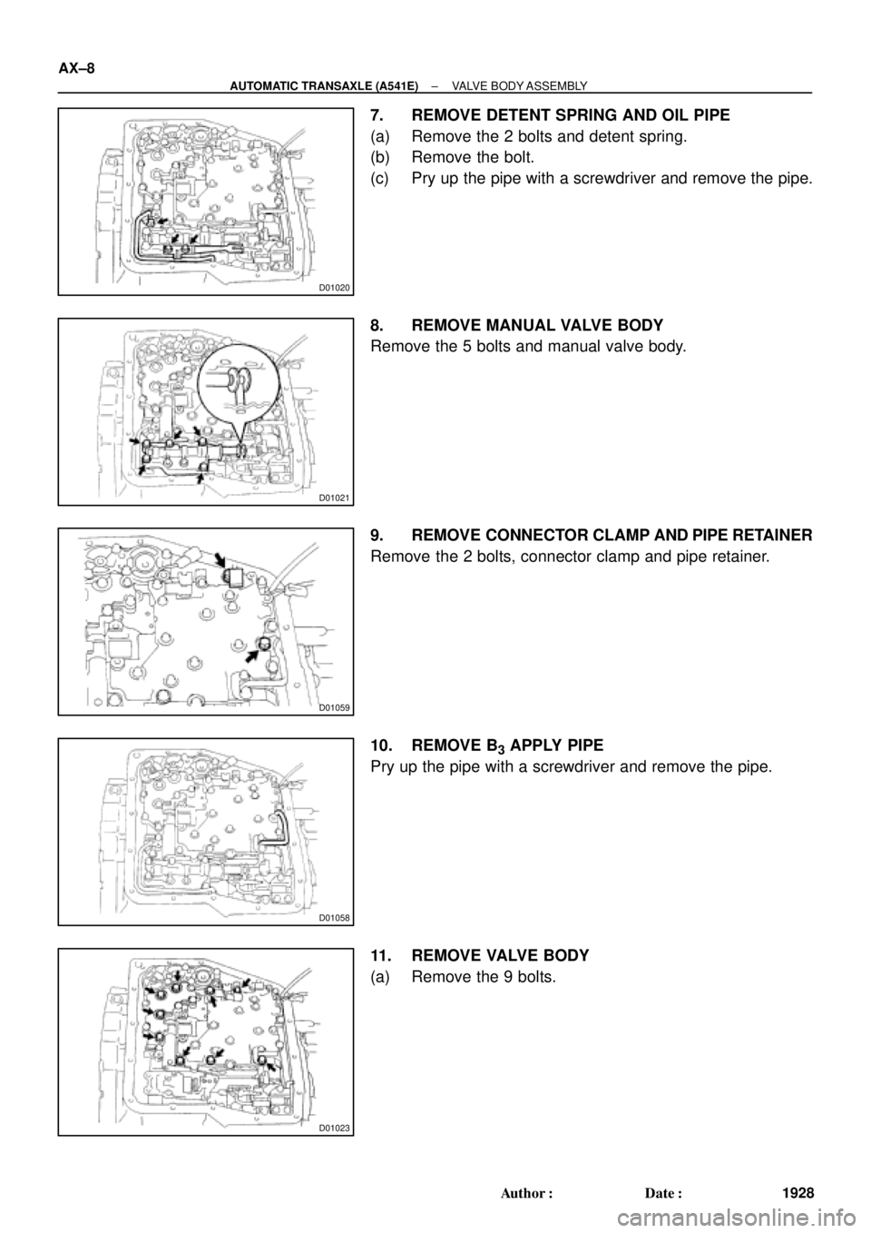
2. REMOVE OIL PAN AND GASKET
NOTICE:
Some fluid will remain in the oil pan.
Remove the oil pan bolts, and carefully remove the oil pan as-
sembly. Discard the gasket.
3. EXAMINE PARTICLES IN PAN
Remove the magnets and use them to collect any steel chips.
Look carefully at the chips and particles in the pan and on the
magnet to anticipate what type of wear you will find in the trans-
axle.
�Steel (magnetic): bearing, gear and plate wear
�Brass (non±magnetic): bushing wear
4. REMOVE MANUAL VALVE BODY DETENT SPRING
AND MANUAL VALVE BODY
(a) Remove the detent spring on the manual valve body.
(b) Remove the manual valve body.
5. REMOVE OIL STRAINER AND OIL PIPE BRACKET
(a) Remove the 3 bolts and the oil strainer.
(b) Remove the 2 bolts and oil pipe bracket.
NOTICE:
Be careful as oil will come out of the strainer when it is re-
moved.
Page 102 of 4592
Z10940
mm (in.)
20
(0.78)
45
(1.772)50
(1.969)
AT3336
Z10944
mm (in.)
36 (1.417)
14 (0.551)
AT2711
Z10945
Magnets
AT2368
Q00073
AX±8
± AUTOMATIC TRANSAXLE (A140E)VALVE BODY ASSEMBLY
1901 Author�: Date�:
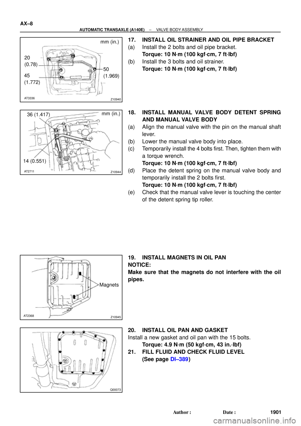
17. INSTALL OIL STRAINER AND OIL PIPE BRACKET
(a) Install the 2 bolts and oil pipe bracket.
Torque: 10 N´m (100 kgf´cm, 7 ft´lbf)
(b) Install the 3 bolts and oil strainer.
Torque: 10 N´m (100 kgf´cm, 7 ft´lbf)
18. INSTALL MANUAL VALVE BODY DETENT SPRING
AND MANUAL VALVE BODY
(a) Align the manual valve with the pin on the manual shaft
lever.
(b) Lower the manual valve body into place.
(c) Temporarily install the 4 bolts first. Then, tighten them with
a torque wrench.
Torque: 10 N´m (100 kgf´cm, 7 ft´lbf)
(d) Place the detent spring on the manual valve body and
temporarily install the 2 bolts first.
Torque: 10 N´m (100 kgf´cm, 7 ft´lbf)
(e) Check that the manual valve lever is touching the center
of the detent spring tip roller.
19. INSTALL MAGNETS IN OIL PAN
NOTICE:
Make sure that the magnets do not interfere with the oil
pipes.
20. INSTALL OIL PAN AND GASKET
Install a new gasket and oil pan with the 15 bolts.
Torque: 4.9 N´m (50 kgf´cm, 43 in.´lbf)
21. FILL FLUID AND CHECK FLUID LEVEL
(See page DI±389)
Page 129 of 4592
D01020
D01021
D01059
D01058
D01023
AX±8
± AUTOMATIC TRANSAXLE (A541E)VALVE BODY ASSEMBLY
1928 Author�: Date�:
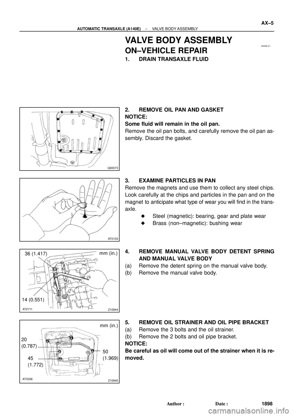
7. REMOVE DETENT SPRING AND OIL PIPE
(a) Remove the 2 bolts and detent spring.
(b) Remove the bolt.
(c) Pry up the pipe with a screwdriver and remove the pipe.
8. REMOVE MANUAL VALVE BODY
Remove the 5 bolts and manual valve body.
9. REMOVE CONNECTOR CLAMP AND PIPE RETAINER
Remove the 2 bolts, connector clamp and pipe retainer.
10. REMOVE B
3 APPLY PIPE
Pry up the pipe with a screwdriver and remove the pipe.
11. REMOVE VALVE BODY
(a) Remove the 9 bolts.
Page 132 of 4592
D01059
A
B
D01021
B
B
A
Z19257
30
(1.18)
BAmm (in.)
Q05728
Connector
± AUTOMATIC TRANSAXLE (A541E)VALVE BODY ASSEMBLY
AX±11
1931 Author�: Date�:
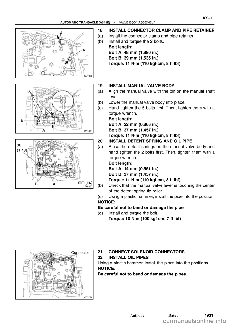
18. INSTALL CONNECTOR CLAMP AND PIPE RETAINER
(a) Install the connector clamp and pipe retainer.
(b) Install and torque the 2 bolts.
Bolt length:
Bolt A: 48 mm (1.890 in.)
Bolt B: 39 mm (1.535 in.)
Torque: 11 N´m (110 kgf´cm, 8 ft´lbf)
19. INSTALL MANUAL VALVE BODY
(a) Align the manual valve with the pin on the manual shaft
lever.
(b) Lower the manual valve body into place.
(c) Hand tighten the 5 bolts first. Then, tighten them with a
torque wrench.
Bolt length:
Bolt A: 22 mm (0.866 in.)
Bolt B: 37 mm (1.457 in.)
Torque: 11 N´m (110 kgf´cm, 8 ft´lbf)
20. INSTALL DETENT SPRING AND OIL PIPE
(a) Place the detent springs on the manual valve body and
hand tighten the 2 bolts first. Then, tighten them with a
torque wrench.
Bolt length:
Bolt A: 14 mm (0.551 in.)
Bolt B: 37 mm (1.457 in.)
Torque: 11 N´m (110 kgf´cm, 8 ft´lbf)
(b) Check that the manual valve lever is touching the center
of the detent spring tip roller.
(c) Using a plastic hammer, install the pipe into the position.
NOTICE:
Be careful not to bend or damage the pipe.
(d) Install and torque the bolt.
Torque: 10 N´m (100 kgf´cm, 7 ft´lbf)
21. CONNECT SOLENOID CONNECTORS
22. INSTALL OIL PIPES
Using a plastic hammer, install the pipes into the positions.
NOTICE:
Be careful not to bend or damage the pipes.
Page 161 of 4592
INTRODUCTIONABBREVIATIONS USED IN THIS MANUAL ±
IN±9
ABBREVIATIONS USED IN THIS
MANUAL
AT FAutomatic Transaxle Fluid
B0Overdrive Brake
B1Second coast Brake
B2Second Brake
B3First and Reverse Brake
C0Overdrive Direct Clutch
C1Forward Clutch
C2Direct Clutch
DDisc
FFlange
F0O/D One±way Clutch
F1No.1 One±way Clutch
F2No.2 One±way Clutch
MPMultipurpose
O/DOverdirve
PPlate
SSMSpecial Service Materials
SSTSpecial Service Tools
IN01H±0R
Page 170 of 4592
AUTOMATIC TRANSAXLESERVICE SPECIFICATIONS ±
AX±18
TORQUE SPECIFICATION
Part tightenedN´mkgf´cmft´lbf
Stator shaft x Oil pump body101007
Upper valve body x Lower valve body5.45548
Ring gear x Differential case9798571
Side bearing cap x Transaxle case7273053
Bearing retainer x Transaxle case1919514
Counter drive gear x Drive pinion1721,750127
Carrier cover x Transaxle case2525018
Parking lock pawl bracket7.47565 in.´lbf
Overdrive case x Transaxle case2526019
Oil pump x Transaxle case2222016
Valve body x Transaxle case101007
Manual valve body x Transaxle case101007
Detent spring x Valve body101007
Oil tube bracket x Transaxle case101007
Oil strainer x Valve body101007
Oil pan x Transaxle case4.95043 in.´lbf
Park/Neutral position switch6.97061 in.´lbf
Park/Neutral position switch adjusting bolt5.45548 in.´lbf
Union2727520
AT06Q±0C
Page 185 of 4592
AUTOMATIC TRANSAXLECOMPONENT PARTS REMOVAL ±
AX±15
SEPARATE BASIC SUBASSEMBLY
1. REMOVE PARK/NEUTRAL POSITION SWITCH
(a) Remove the manual shift lever.
(b) Pry off the lock washer and remove the manual valve
shaft nut.
(c) Remove the 2 bolts and pull out the park/neutral position
switch.
2. REMOVE UNION AND ELBOW
(a) Using the open end wrench, remove the union and elbow.
(b) Remove the O±rings from the union and elbow.
3. REMOVE SL SOLENOID
(a) Disconnect the connector.
(b) Remove the 2 bolts and SL solenoid.
4. REMOVE THROTTLE CABLE RETAINING PLATE
5. REMOVE SOLENOID WIRE RETAINING BOLT
6. REMOVE COVER
(a) Remove the 2 bolts and cover bracket.
AX0EW±02
Page 187 of 4592
AUTOMATIC TRANSAXLECOMPONENT PARTS REMOVAL ±
AX±17
11. REMOVE OIL TUBES
Pry up both tube ends with a large screwdriver and re-
move the 4 tubes.
12. REMOVE MANUAL DETENT SPRING
13. REMOVE MANUAL VALVE AND MANUAL VALVE
BODY
14. REMOVE VALVE BODY
(a) Remove the 12 bolts.
15. REMOVE THROTTLE CABLE AND SOLENOID WIR-
ING FROM CASE
16. REMOVE SECOND BRAKE APPLY GASKET