Page 2906 of 4592

B00319
Recommended Viscosity (SAE):
TEMPERATURE RANGE ANTICIPATED BEFORE NEXT OIL CHANGE10W±30
5W±30 PREFERRED°C °F
±20
±290
±1820
±740
460
1680
27100
38
LU0FR±01
P25173SST
P25171
Oil Pressure Gauge
± LUBRICATION (1MZ±FE)OIL AND FILTER
LU±1
1665 Author�: Date�:
OIL AND FILTER
INSPECTION
1. CHECK ENGINE OIL QUALITY
Check the oil for deterioration, entry of water, discoloring or thin-
ning.
If the quality is visibly poor, replace the oil.
Oil grade:
API grade SJ, Energy±Conserving or ILSAC multi-
grade engine oil.
SAE 5W ± 30 is the best choice for your vehicle, for
good fuel economy, and good starting in cold weath-
er.
2. CHECK ENGINE OIL LEVEL
After warm up the engine and then 5 minutes after the engine
stop, oil level should be between the low level and full level
marks on the dipstick.
If low, check for leakage and add oil up to the full level mark.
NOTICE:
Do not fill with engine oil above the full level mark.
3. REMOVE OIL PRESSURE SWITCH, AND INSTALL
OIL PRESSURE GAUGE
(a) Using SST, remove the oil pressure switch.
SST 09816±30010
(b) Install the oil pressure gauge.
4. WARM UP ENGINE
Allow the engine to warm up to normal operating temperature.
5. CHECK OIL PRESSURE
Oil pressure:
At idle29 kPa (0.3 kgf/cm2, 4.3 psi) or more
At 3,000 rpm294 ± 539 kPa (3.0 ± 5.5 kgf/cm2, 43 ± 78 psi)
Page 2927 of 4592

MA003±09
MA±4
± MAINTENANCEUNDER HOOD
47 Author�: Date�:
UNDER HOOD
GENERAL MAINTENANCE
1. GENERAL NOTES
�Maintenance items may vary from country to country. Check the owner's manual supplement in which
the maintenance schedule is shown.
�Every service item in the periodic maintenance schedule must be performed.
�Periodic maintenance service must be performed according to whichever interval in the periodic main-
tenance schedule occurs first, the odometer reading (miles) or the time interval (months).
�Maintenance service after the last period should be performed at the same interval as before unless
otherwise noted.
�Failure to do even one item an cause the engine to run poorly and increase exhaust emissions.
2. WINDSHIELD WASHER FLUID
Check that there is sufficient fluid in the tank.
3. ENGINE COOLANT LEVEL
Check that the coolant level is between the ºFULLº and ºLOWº lines on the see±through reservoir.
4. RADIATOR AND HOSES
(a) Check that the front of the radiator is clean and not blocked with leaves, dirt or bugs.
(b) Check the hoses for cracks, kinks, rot or loose connections.
5. BATTERY ELECTROLYTE LEVEL
Check that the electrolyte level of all battery cells is between the upper and lower level lines on the case.
6. BRAKE AND CLUTCH FLUID LEVELS
(a) Check that the brake and clutch fluid levels are near the upper level line on the see±through reservoirs.
(b) Check that the clutch fluid level is with is ± 5 mm (0.20 in.). of the reservoir hem.
7. ENGINE DRIVE BELTS
Check drive belt for fraying, cracks, wear or oiliness.
8. ENGINE OIL LEVEL
Check the level on the dipstick with the engine turned off.
9. POWER STEERING FLUID LEVEL
�Check the level.
�The level should be in the ºHOTº or ºCOLDº range depending on the fluid temperature.
10. AUTOMATIC TRANSMISSION FLUID LEVEL
(a) Park the vehicle on a level surface.
(b) With the engine idling and the parking brake applied, shift the selector into all positions from ºPº to ºLº,
and then shift into ºPº position.
(c) Pull out the dipstick and wipe off the fluid with a clean rag. Re±insert the dipstick and check that the
fluid level is in the HOT range.
(d) Do this check with the fluid at normal driving temperature (70 ± 80°C, 158 ± 176°F).
HINT:
Wait until the engine cools down (approx. 30 min.) before checking the fluid level after extended driving at
high speeds, in hot weather, in heavy traffic or pulling a trailer.
11. EXHAUST SYSTEM
If any change in the sound of the exhaust or smell of the exhaust fumes is noticed, have the cause located
and corrected.
Page 3259 of 4592

SS109±02
± SERVICE SPECIFICATIONSSFI (1MZ±FE)
SS±21
184 Author�: Date�:
SFI (1MZ±FE)
SERVICE DATA
Fuel pressure
regulatorFuel pressure at no vacuum301 ± 347 kPa (3.1 ± 3.5 kgf/cm2, 44 ± 50 psi)
Fuel pumpResistance at 20°C (68°F)0.2 ± 3.0 W
InjectorResistance
Injection volume
Difference between each cylinder
Fuel leakage13.4 - 14.2 W
60 ± 73 cm3 (3.4 ± 4.5 cu in.) per 15 sec.
13 cm3 (0.8 cu in.) or less
1 drop or less per 12 minute
MAF meterResistance (THA ± E2) at ±20°C (±4°F)
at 20°C (68°F)
at 60°C (140°F)14.6 ± 17.8 kW
2.21 ± 2.69 kW
0.29 ± 0.35 kW
Throttle bodyThrottle opener setting speed900 ± 1,950 rpm
Throttle
position
sensorResistance
Throttle valve fully closed VTA ± E2
Throttle valve fully open VTA ± E2
± VC ± E2
0.2 ± 6.3 kW
2.0 ± 10.2 kW
2.5 ± 5.9 kW
IAC valveResistance (+B ± RSO or RSC) at cold
at hot17.0 ± 25.0 W
21.5 ± 29.5 W
VSV for EGRResistance at 20°C (68°F)27 ± 33 W
VSV for EVAPResistance at 20°C (68°F)27 ± 33 W
VSV for ACISResistance at 20°C (68°F)33 ± 39 W
VSV for Vapor
Pressure SensorResistance at 20°C (68°F)33 ± 39 W
Vapor
Pressure
SensorPower source voltage4.5 ± 5.5 V
ECT sensorResistance at ±20°C (±4°F)
at 0°C (32°F)
at 20°C (68°F)
at 40°C (104°F)
at 60°C (140°F)
at 80°C (176°F)10 ± 20 kW
4 ± 7 kW
2 ± 3 kW
0.9 ± 1.3 kW
0.4 ± 0.7 kW
0.2 ± 0.4 kW
EGR gas
temperature
sensorResistance at 50°C (122°F)
at 100°C (212°F)
at 150°C (302°F)64 ± 97 kW
11 ± 16 kW
2 ± 4 kW
A/F sensorHeater coil resistance at 20°C (68°F)
at 800°C (1472°F)0.8 ± 1.4 W
1.8 ± 3.2 W
Heated
oxygen sensorHeater coil resistance at 20°C (68°F)
at 800°C (1472°F)11 ± 16 W
23 ± 32 W
Fuel cut rpmFuel return rpm1,200 rpm
Page 3316 of 4592

SS0AH±04
SS±6
± SERVICE SPECIFICATIONSSFI
TORQUE SPECIFICATION
Part tightenedN´mkgf´cmft´lbf
Fuel line for union for fuel inlet coupler
for others42
28428
28631
21
Fuel filter x Drain plug10.811 08
Fuel filter x Fuel filter bracket21.521916
Fuel filter x Union3131623
Oil separator x Fuel pressure regulator24.525018
Fuel pressure regulator x Bracket2020015
Fuel pressure regulator bracket x Body for 10 mm head bolt
for 12 mm head bolt9.9
19.6100
20088 in.´lbf
14
Fuel relief pipe x Fuel pressure regulator4242831
Delivery pipe x cylinder head1313010
Fuel tank band x Fuel tank frame5253038
Rear side plate x Front side plate1001,02074
Union x Fuel shutoff valve for fuel pipe filter pipe
for others31
18316
18423
13
Fuel tank bracket x Fuel tank valve case8.28473 in.´lbf
Fuel tank valve cover x Fuel tank valve case8.28473 in.´lbf
Fuel tank frame x Body60.261444
Performance rod x Body39.240029
Performance rod x Fuel tank band18.118513
Fuel shutoff valve core x Delivery pipe3535726
Fuel shutoff valve coil x Core1515311
Fuel temperature sensor x Delivery pipe20.420815
Fuel pressure sensor x Delivery pipe24.625118
Fuel pressure sensor x Fuel main pipe68.670051
Fuel inlet hose x Fuel pressure regulator9.910088 in.´lbf
Page 3357 of 4592

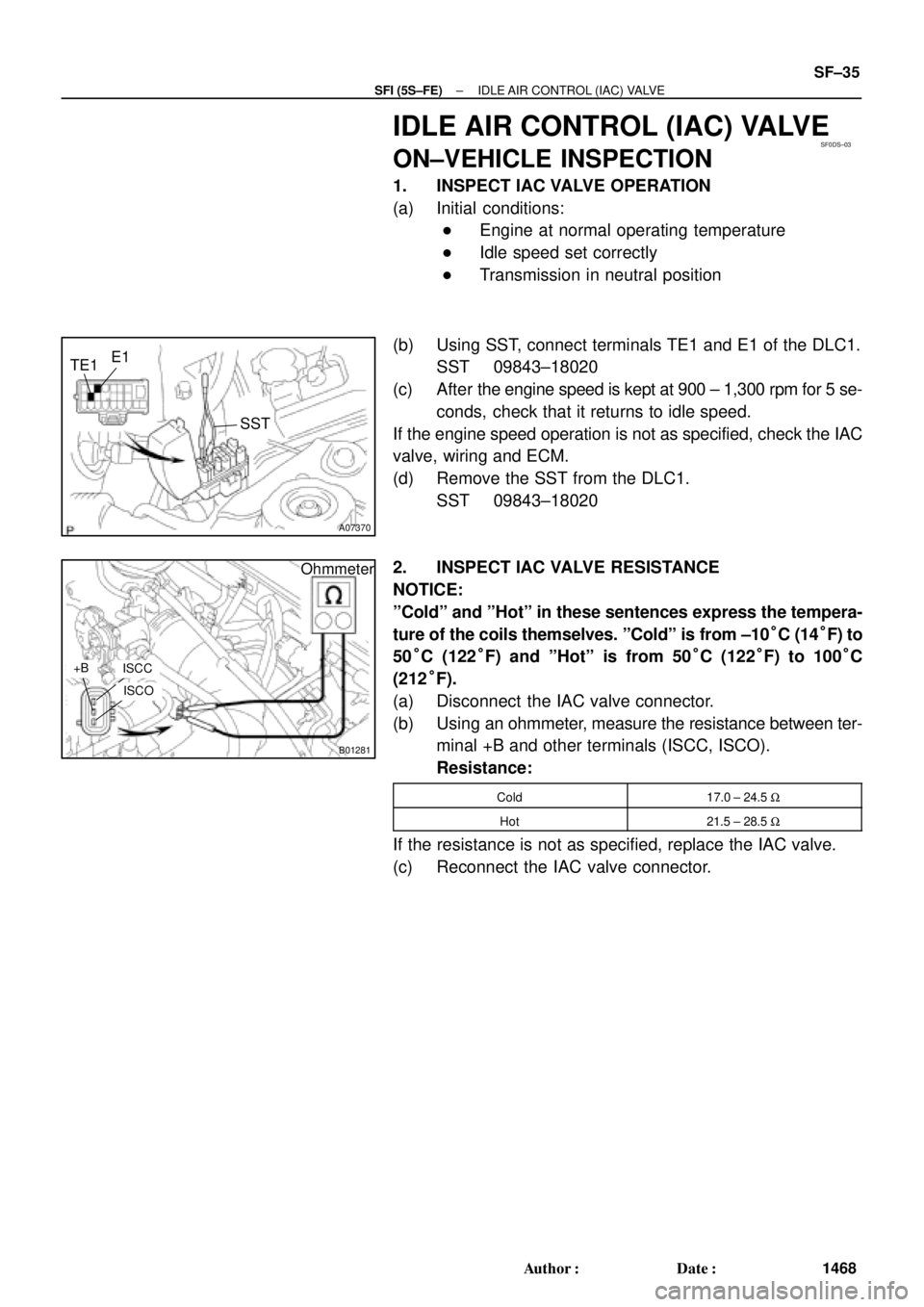
SF0DS±03
A07370
SST
E1
TE1
B01281
Ohmmeter
ISCC+B
ISCO
± SFI (5S±FE)IDLE AIR CONTROL (IAC) VALVE
SF±35
1468 Author�: Date�:
IDLE AIR CONTROL (IAC) VALVE
ON±VEHICLE INSPECTION
1. INSPECT IAC VALVE OPERATION
(a) Initial conditions:
�Engine at normal operating temperature
�Idle speed set correctly
�Transmission in neutral position
(b) Using SST, connect terminals TE1 and E1 of the DLC1.
SST 09843±18020
(c) After the engine speed is kept at 900 ± 1,300 rpm for 5 se-
conds, check that it returns to idle speed.
If the engine speed operation is not as specified, check the IAC
valve, wiring and ECM.
(d) Remove the SST from the DLC1.
SST 09843±18020
2. INSPECT IAC VALVE RESISTANCE
NOTICE:
ºColdº and ºHotº in these sentences express the tempera-
ture of the coils themselves. ºColdº is from ±10°C (14°F) to
50°C (122°F) and ºHotº is from 50°C (122°F) to 100°C
(212°F).
(a) Disconnect the IAC valve connector.
(b) Using an ohmmeter, measure the resistance between ter-
minal +B and other terminals (ISCC, ISCO).
Resistance:
Cold17.0 ± 24.5 W
Hot21.5 ± 28.5 W
If the resistance is not as specified, replace the IAC valve.
(c) Reconnect the IAC valve connector.
Page 3430 of 4592

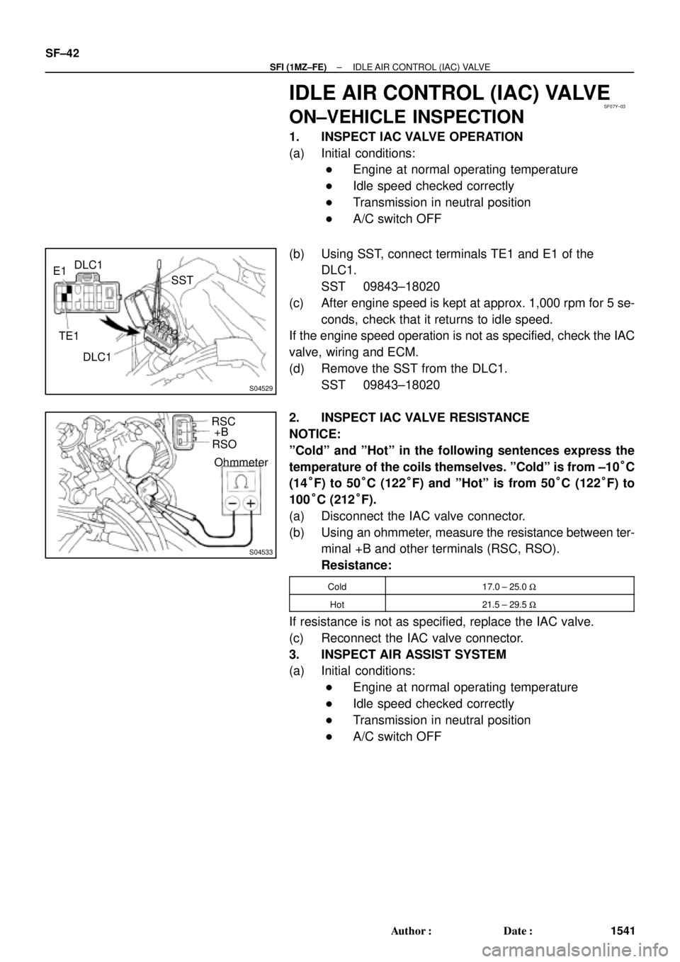
SF07Y±03
S04529
E1DLC1
SST
TE1
DLC1
S04533
RSC
+B
RSO
Ohmmeter SF±42
± SFI (1MZ±FE)IDLE AIR CONTROL (IAC) VALVE
1541 Author�: Date�:
IDLE AIR CONTROL (IAC) VALVE
ON±VEHICLE INSPECTION
1. INSPECT IAC VALVE OPERATION
(a) Initial conditions:
�Engine at normal operating temperature
�Idle speed checked correctly
�Transmission in neutral position
�A/C switch OFF
(b) Using SST, connect terminals TE1 and E1 of the
DLC1.
SST 09843±18020
(c) After engine speed is kept at approx. 1,000 rpm for 5 se-
conds, check that it returns to idle speed.
If the engine speed operation is not as specified, check the IAC
valve, wiring and ECM.
(d) Remove the SST from the DLC1.
SST 09843±18020
2. INSPECT IAC VALVE RESISTANCE
NOTICE:
ºColdº and ºHotº in the following sentences express the
temperature of the coils themselves. ºColdº is from ±10°C
(14°F) to 50°C (122°F) and ºHotº is from 50°C (122°F) to
100°C (212°F).
(a) Disconnect the IAC valve connector.
(b) Using an ohmmeter, measure the resistance between ter-
minal +B and other terminals (RSC, RSO).
Resistance:
Cold17.0 ± 25.0 W
Hot21.5 ± 29.5 W
If resistance is not as specified, replace the IAC valve.
(c) Reconnect the IAC valve connector.
3. INSPECT AIR ASSIST SYSTEM
(a) Initial conditions:
�Engine at normal operating temperature
�Idle speed checked correctly
�Transmission in neutral position
�A/C switch OFF
Page 3461 of 4592
SF08O±04
S04504
P03193
Oil
Ohmmeter SF±70
± SFI (1MZ±FE)EXHAUST GAS RECIRCULATION (EGR) GAS
TEMPERATURE SENSOR
1569 Author�: Date�:
INSPECTION
1. REMOVE THROTTLE BODY (See page SF±39)
2. REMOVE EGR GAS TEMPERATURE SENSOR
3. INSPECT EGR GAS TEMPERATURE SENSOR
Using an ohmmeter, measure the resistance between the ter-
minals.
Resistance:
At 50°C (122°F)64 ± 97 kW
At 100°C (212°F)11 ± 16 kW
At 150°C (302°F)2 ± 4 kW
If the resistance is not as specified, replace the sensor.
4. REINSTALL EGR GAS TEMPERATURE SENSOR
5. REINSTALL THROTTLE BODY (See page SF±41)
Page 3511 of 4592

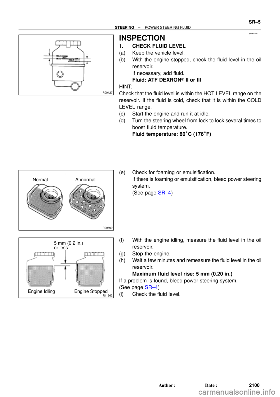
SR06F±01
R00427
R09599
Normal Abnormal
R11562
5 mm (0.2 in.)
or less
Engine Idling Engine Stopped
± STEERINGPOWER STEERING FLUID
SR±5
2100 Author�: Date�:
INSPECTION
1. CHECK FLUID LEVEL
(a) Keep the vehicle level.
(b) With the engine stopped, check the fluid level in the oil
reservoir.
If necessary, add fluid.
Fluid: ATF DEXRON® II or III
HINT:
Check that the fluid level is within the HOT LEVEL range on the
reservoir. If the fluid is cold, check that it is within the COLD
LEVEL range.
(c) Start the engine and run it at idle.
(d) Turn the steering wheel from lock to lock several times to
boost fluid temperature.
Fluid temperature: 80°C (176°F)
(e) Check for foaming or emulsification.
If there is foaming or emulsification, bleed power steering
system.
(See page SR±4)
(f) With the engine idling, measure the fluid level in the oil
reservoir.
(g) Stop the engine.
(h) Wait a few minutes and remeasure the fluid level in the oil
reservoir.
Maximum fluid level rise: 5 mm (0.20 in.)
If a problem is found, bleed power steering system.
(See page SR±4)
(i) Check the fluid level.